Dmitry Levkin
- Three-phase squirrel-cage induction motor Design of an asynchronous electric motor
- Operating principle of a three-phase motor
- Slip of induction motor
- Three-phase alternating current
- Direct connection to mains power
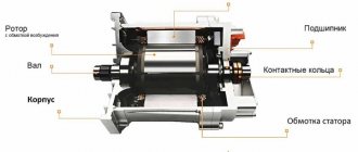
- Three-phase asynchronous motor with wound rotor Design features
- Designation of rotor terminals
- Start ADFR
Three-phase asynchronous electric motor
is an asynchronous electric motor that has a three-phase stator winding.
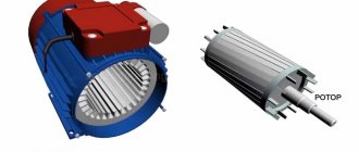
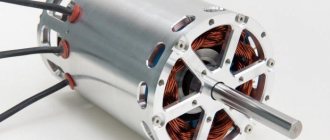
Engine structure
The main elements of an electric motor are the stator, the rotor, their windings and the magnetic circuit.
The conversion of electrical energy into mechanical energy occurs in the rotating part of the motor - the rotor.
In an AC motor, the rotor receives energy not only through the magnetic field, but also through induction. Thus, they are called asynchronous motors. This can be compared to the secondary winding of a transformer. These asynchronous motors are also called rotating transformers. Most often, models designed for three-phase connection are used.
Asynchronous motor design
The direction of rotation of the electric motor is determined by the left-hand rule of the gimlet: it demonstrates the connection between the magnetic field and the conductor.
The second very important law is Faraday's:
- EMF is induced in the winding, but the electromagnetic flux changes with time.
- The magnitude of the induced emf is directly proportional to the rate of change of electric flux.
- The direction of the emf opposes the current.
Maintenance Recommendations
Maintenance of asynchronous electric motors includes:
Electric motors: design and principle of operationApplication of electric motors
- Electric motor rotor - design features and operating principle of the device. Repair and restoration instructions
- A thorough inspection of the exterior and a mechanical assessment.
- Visual electrical assessment.
- Production of measurements and tests.
The task of maintenance is the timely detection of faulty elements and defects. Its main goal is prevention. Minor faults can be corrected on site. Correcting serious ones will require contacting specialists.
Operating principle
When voltage is applied to the stationary stator windings, it creates a magnetic field in the stator. If AC voltage is applied, the magnetic flux created by it changes. So the stator produces a change in the magnetic field, and the rotor receives magnetic fluxes.
Thus, the rotor of the electric motor receives this stator flux and therefore rotates. This is the basic principle of operation and sliding in asynchronous machines. From the above, it should be noted that the stator magnetic flux (and its voltage) must be equal to the alternating current to rotate the rotor, so that an induction machine can only operate on alternating current.
Operating principle of an asynchronous motor
When such motors act as a generator, they will directly generate alternating current. In the case of such operation, the rotor is rotated by external means, say a turbine. If the rotor has some residual magnetism, that is, some magnetic properties that are retained by the type of magnet inside the material, then the rotor creates an alternating flux in the stationary stator winding. So it is the stator windings that will receive the induced voltage using the principle of induction.
Induction generators are used in small shops and households to provide additional power support and are the least expensive due to easy installation. Recently, they have been widely used by people in those countries where electric machines lose power due to constant voltage drops in the power supply network. Most of the time, the rotor is rotated by a small diesel engine coupled to an asynchronous alternating voltage generator.
Windings
Before we begin to characterize the windings directly on the stator of an electric motor, let's look at what these windings are. They are a set of wire turns, which together form an electrical circuit, which in turn sums up all the electromotive powers induced in these same turns. The coil is the simplest example of such windings, where the turns are sequentially placed next to each other.
Windings are classified into the following groups according to different criteria:
- by method of application - stator and rotor. One of the key classifications;
- according to the method of arrangement in the grooves - two- and single-layer;
- according to the shape of the coils - equal-coil and concentric type;
- by type of frontal parts - two and three stripes, as well as basket (or concentric);
- by type of wire cross-section - hard (consisting of cables with rectangular conductors) and soft (made of round wires).
Many more classifications have been implemented that allow you to select a stator coil according to a certain indicator.
There are also patterned and concentric windings, all of which are single-layer. In the latter case, the winding includes coils, which are located one inside the other.
Example of a concentric winding
The exact number of coil groups is 6p. When the number of pole pairs is even, then the number of coil groups is also indicated as even. At the same time, the first half of such sets are produced with long frontal sections, and the second - with short ones. In situations in which the number is unpaired, one group is realized asymmetrical.
In a concentric winding made of the “waddling” type, groups of coils are classified into two subgroups. Such winding occurs when the q index exceeds 2 and makes it possible to reduce the levels of overhang of the frontal elements due to their more convenient placement.
Sets of coils of asymmetrical design are not used in these types of designs even if there is an even number of pairs of poles. Indicators of electrical resistance when winding cones occur through the same length of the winding components of the coils in phases:
- one phase includes all small subclasses;
- the second – middle level;
- the third is large.
This promotes some changes in the winding. For example, the front winding components of the concentric type are placed in two or three areas at once. Based on this, the windings are of the following types:
- two- or three-plane;
- two- or three-tier.
The above variations occur when the frontal parts are installed on tiers or in planes.
The frontal elements of windings using the “waddling” method are placed in 3 positions at once. These windings are often described as bobbin windings, because they are not always the same due to differences in the length of each individual front part.
Example of waddle winding
Pattern windings are implemented as symmetrical, because the coils have the same dimensions. The simplest among them are template ones, which are shown in the figure below.
Template winding
Next come the standard waddle and chain ones. We looked at their technological features a little higher.
Connection
An induction motor can be stopped by simply swapping any two of the stator terminals. This is used during emergencies. It then changes the direction of the rotating flow, which produces torque, thereby causing a power cut to the rotor. This is called antiphase inhibition.
Video: How an asynchronous motor works
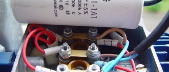
To prevent this from happening in a single-phase asynchronous motor, it is necessary to use a capacitor device.
It needs to be connected to the starting winding, but it must first be calculated. Formula
QC = Uс I 2 = U 2 I 2 / sin 2
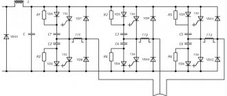
Diagram: Connecting an asynchronous motor
From which it follows that AC electric machines of two-phase or single-phase type must be equipped with capacitors with a power equal to the engine power itself.
For low voltage
It may be that the same tablet says Δ/Ỵ 127/220. This suggests that a “star” winding connection circuit is required. If there is no terminal box, the motor is connected in a triangle, and the ends, as often happens, are not labeled - no problem. There is a solution to the problem. True, in this case everything is somewhat more complicated and will take more time.
Separate all the ends and use an ohmmeter to find the stator coils.
Mark them with tape or colored tape. Perhaps this will come in handy more than once.
Take the battery and connect it to a1-a2. Connect an ohmmeter to b1-b2.
When the contact with the battery is broken, the needle on the ohmmeter will move to the side. Remember exactly where the arrow pointed and connect the device to c1-c2. There is no need to change the polarity. Do it all again.
The arrow may swing in the other direction. In this case, the wires need to be swapped and the markings changed. The arrow should only deviate in one direction.
The battery, on which the polarity is observed, is connected to c1-c2, and the measuring device to a1-a2.
Now everything needs to be rechecked. The needle should deflect equally on all reels. If everything is correct, a bunch with the same numbers (let’s say 1) is the beginning, and a bunch with the number 2 is the end.
All three ends (a2, b2, c2) need to be connected and insulated. This is a star connection. It can be displayed on the terminal block, marked for convenience, or drawn or pasted on a diagram according to which the windings are connected.
Switching from delta to star is ready. The device can be connected to the network.
Clutch analogy
Considering the principle of operation of an asynchronous electric motor used in industrial machines and its technical characteristics, it is necessary to say something about a rotating mechanical clutch. The torque on the drive shaft must be equal to the torque on the driven shaft. Additionally, it should be emphasized that these two torques are one and the same, since the torque of a linear transducer is caused by friction between the discs within the clutch itself.
Electromagnetic clutch
A traction motor with a wound rotor has a similar operating principle. The system of such a motor consists of eight poles (of which 4 are main, and 4 are additional), and a frame. The main poles contain copper coils. The rotation of such a mechanism is due to a gear transmission, which receives torque from the armature shaft, also called the core. Connection to the network is carried out using four flexible cables. The main purpose of a multi-pole electric motor is to drive heavy equipment: diesel locomotives, tractors, combines and, in some cases, machine tools.
Brief historical background
The first asynchronous motor was invented during the Russian Empire, namely on March 8, 1889. The author of the invention was the great Russian master of engineering M. O. Dolivo-Dobrovolsky.
Today, the scope of use of such electric motors is quite wide. They are considered the most common type of engine, as they have made a technical revolution in the industrial sector.
The following description of asynchronous electric motors can be given: this is the only type of motor in which the poles are created due to a phenomenon called induction. Therefore, they are often called induction.
Other devices use coils powered by current, magnets, and only in asynchronous electric machines interference is used - it is they that create the driving force.
Advantages and disadvantages
The design of an asynchronous motor is almost universal, but this mechanism also has its pros and cons.
Advantages of AC asynchronous motors:
- Simple design.
- Low production cost.
- Reliable and easy to use design.
- Not fussy to use.
- Simple control scheme
The efficiency of these motors is very high as there are no friction losses and a relatively high power factor.
Disadvantages of AC induction motors:
- Speed control is not possible without loss of power.
- If the load increases, the torque decreases.
- Relatively low starting torque.
DC machines are more often used as motors because they have the following advantages:
- — high starting torque;
- - ability to widely adjust speed;
- - easy to reverse;
- — have almost linear adjustment characteristics;
- - economical.
These advantages often make them unrivaled in drives that require extensive and precise adjustments. An important advantage of DC machines is also the possibility of their regulation via low-current excitation circuits.
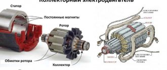
DC machines are used only where it is impossible to find an equivalent replacement. This is due to the presence of a brush-collector unit, which causes most of the machine’s shortcomings, the main of which are:
- - the cost increases;
- — the work resource is reduced;
- — radio interference and acoustic noise are created;
- — sparking under the brushes accelerates wear of the brushes and commutator plates.
- — wear products cover the internal cavity of the machine with a thin conductive layer, worsening the insulation of current-carrying circuits.
Catalog of publications
- Preschool education
- Primary and basic general education
- Secondary vocational education
- Exchange of teaching experience
- Children's research projects and works
- Works published before November 2022
Post a publicationList of all publications Published works: 13053
Presentation: AC Electrical Machines
Volkorezov Andrey Timurovich, Yaroslavl
Prepared by: cadet Volkorezov A.T. Report on the topic: “Alternating current electric machines: scope, examples, advantages and disadvantages.”
Study questions: Asynchronous motors. Principle of operation. Classification of AC electrical machines. Advantages and disadvantages of AC electrical machines.
Classification of AC electrical machines. AC EVs can be synchronous (usually generators) and asynchronous (usually motors). Asynchronous ones, in turn, can be with a squirrel-cage or wound-wound rotor. Let's look at examples of AD.
Single-phase asynchronous motor A single-phase asynchronous motor contains only one working winding on the stator, to which alternating current is supplied during engine operation. But to start the engine, there is also an additional winding on its stator, which is briefly connected to the network through a capacitor or inductance, or is short-circuited. This is necessary to create an initial phase shift so that the rotor begins to rotate, otherwise the pulsating magnetic field of the stator would not push the rotor out of place.
For high voltage
Let's say the plate has the following data: Δ/Ỵ220/380. This inscription indicates that the motor requires a delta connection. If you have a terminal box, this will not be difficult. The jumpers will simply switch to the required position.
If there is no terminal box and there are only wires in front of you, the entire unit will have to be disassembled. When you get to the stator, you will see three ends of the wires, they will be soldered. You have found a star connection. They need to be disconnected from each other and connected in a triangle pattern.
Overall, it's not very difficult. Remember that a reel has a beginning and an end, do not confuse them. If the beginning is what is brought out into the engine boron, then the ends are soldered.
The connection occurs like this: the end of one coil is soldered to the beginning of the other.
With the help of such simple manipulations, we made a motor designed for a voltage of 380 V, suitable for connecting to a 220 V network.