Before you figure out how to connect a current transformer, you need to understand what a transformer is and why it is needed. A transformer is an electromagnetic device that is designed to convert voltage values. Moreover, its operation is possible only with alternating voltage or, in extreme cases, with pulsating voltage. If a pure direct voltage is connected to any transformer, then at its output the potential between the terminals will be zero. Every transformer consists of a primary winding and one or more secondary windings, depending on its purpose and design.
Purpose and design features
In turn, a current transformer is a device that operates on the principle of electromagnetic induction and serves to measure current in high-voltage circuits, as well as to organize protection systems for electrical equipment.
That is, in order to measure current in circuits with dangerously high voltages, for example, 6 kV, you cannot simply take a measurement with an ammeter; this is very dangerous both for personnel and for the device itself. Therefore, the main task of current transformers is to separate high-voltage current-carrying parts and convert energy that is safe for both personnel and equipment. Current transformers (CTs) are widely used in relay protection at substations and switchgears. Therefore, high demands are placed on their accuracy and connection. Often, its primary winding is any conductive busbar or cable core; the secondary winding is single or group, with several terminals for protection, control and measurement circuits. Also, metering elements - electricity meters - are connected through current transformers. That is, according to their purpose, current transformers can be divided into four main groups:
- measuring;
- protective;
- intermediate;
- laboratory
One type of portable device is a clamp meter. They can very easily measure currents in circuits up to 1 kV. True, their measurement range for current is very small; it will be problematic for them to measure loads of 1000 Amps.
General structure and principle of operation
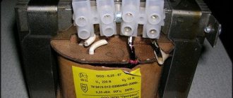
A step-down transformer from 220 to 12 volts is bought by drivers, summer residents, owners of country houses, cottages for the installation of an intra-house low-voltage lighting network. At times, the use of 220 volt electrical power in the home is not economically rational.
The product consists of four main parts: two core rods and two coils of copper wire of the required cross-section and length. They are called windings containing an unequal number of turns. Core rods are made from special steel used in the electrical industry. Transformer 220 is supplied with utility current.
In the primary winding, intense movement of electrons begins, creating an electromotive force. A magnetic field is formed, crossed by the second winding. Electric potentials appear in it, since the magnetic field of the first coil causes self-induction (the movement of electrons) in the second. A difference in electrical levels arises, tending to equalize the potential values to zero.
The flow of electrons from a high potential to a final zero potential creates an electric current. The voltage in the secondary winding depends on how many times it has fewer turns than the first. It should be remembered that the step-down electrical device generates an alternating voltage in the end winding with a change in polarity 50 times per second. They also obtain direct current by connecting a rectifier to the system in order to have 12 volts of direct current at the output.
There is a wide range of electronic step-down products that do not contain cores or coils.
Step-down devices are microscopic electronic circuits coupled with capacitors, resistors and other important components. They have undeniable advantages over traditional current converters, which include:
- in compactness;
- in weight;
- in manual adjustment of reduced voltage;
- in silent operation;
- in high efficiency.
How to install a current transformer
How it works and how to choose a current transformer
According to the type and method of installation, they are divided into:
- Passage;
- Support;
- Built into electrical equipment;
- For electrical installations up to 1 kV or higher;
- For outdoor installation in outdoor switchgear (open switchgear);
- For indoor installation in closed switchgear (closed switchgear).
Often, in circuits with low-power motors and transformers designed for 1 kV and below, the installation of a current transformer is not required. These are all kinds of step-down lighting transformers, compressors, fans, heating systems. In general, current transformers are installed extremely rarely in everyday life, except on transformers that supply entire areas or groups of houses.
Current transformer connection
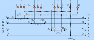
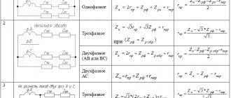
Let's consider several options for connecting current transformers in a three-phase voltage circuit.
This circuit, where three current transformers are connected in a star, is widely used to protect circuits from single-phase and multi-phase short circuits. If a current flows in the circuits below that for which relays KA1-KA3 are configured, then this is called normal operating mode and none of the protections will operate. The current that flows through the K0 relay is calculated as the geometric sum of the currents of all three phases. When the current increases in one of the phases, the current will increase and one or more relays KA1-KA3 will operate in the protective transformer circuit, depending on the location of the current increase. This does not necessarily happen during a short circuit; even if the load on the controlled equipment is higher than the rated load, it will cause a shutdown. Thereby saving expensive electrical equipment from abnormal operation. If there is a ground fault, current will also appear in the K0 relay circuit, thereby turning off the electrical installation.
A circuit with transformers is used to protect against phase-to-phase faults to organize circuits with a grounded neutral. A partial star circuit is most often used for low-power sources and consumers, when there are additional types of various protections.
This type of connection into a triangle on one side and a star on the other is used in electrical installations for differential protection.
Connecting current transformers, thus, makes it possible to protect against phase-to-phase faults and overcurrent in each phase, but there is no shutdown in the event of a short circuit to ground. Therefore, it is connected this way in exceptional, very rare cases.
Connection diagrams for a three-phase electricity meter
Only a correctly connected meter correctly determines and controls the amount of current used. Therefore, the device must be connected correctly. The mounting scheme is determined by the type.
Semi-indirect
It is mounted into the network with a TT. Therefore, it is possible to connect to networks with high powers. Up to 60 kW is allowed. Using this accounting method, to establish expenses, it is worth multiplying the difference in indicators by a certain transformation value.
Ten-wire
She is very popular. This is what experts recommend installing now. After all, it has a number of advantages. They do not have a galvanic connection between the current circuits of the meter and voltage circuits. Therefore, connecting it is much safer. And thanks to it, it is more convenient to carry out manipulations.
There is no need to turn off the settings when changing the meter or when carrying out various manipulations. It is distinguished by its correctness. After all, information collection for all phases occurs independently. If there is a violation of the metering circuits in any of the phases, the functioning of the metering in other phases continues.
The 3-phase meter must be installed carefully for proper functioning. Particular attention should be paid to labeling. The 10-wire requires more wires than other circuits.
The 10-wire has a drawback: significant conductor consumption for assembling secondary metering circuits.
Seven-wire
It got its name because of the number of wires used during connection. It is considered outdated, although it can be found.
The transformer meter must have a contact panel. If it is not there, then there must be a block. They serve as a connection conductor. They are located in the middle of the electrical cord and the meter.
Current transformer installation
Current transformer - operating principle, purpose and device
Before installing the current transformer itself, it is necessary to inspect it and check the insulation resistance. If it is low, that is, less than 1 kOhm per 1 Volt, then first dry it thoroughly using a fan heater or other heat gun. The insulation resistance should be checked every half hour. During the audit, they also check the completeness of the device, fastening elements, the condition of the porcelain dielectric parts and the housing. Need to inspect:
- secondary terminal block for protection and control circuits;
- presence of their designations, markings;
- passport table;
- condition of the threads on the bolted connections of the terminals;
- presence of nuts and washers.
Before you begin directly installing the current transformer, of course, everything starts with turning off the high-voltage installation, checking that there is no voltage on live parts, and also installing portable grounding connections. All this is the main safety measure for installation personnel. Then markings are made at the installation site, and if necessary, drilling work is carried out in the places where the structure is attached. If the room is damp, then it is worth taking measures to prevent the formation of corrosion (installing dryers and painting contact connections). It is prohibited to install the transformer and install it in such a way that their housings are close to each other. The distance must be at least 100 mm.
It is advisable, if possible, that the markings should be visible from behind the fences.
The main rule for connecting any current transformer is to prohibit its inclusion in a circuit without a load on the secondary winding. If it is not possible to connect the device, then they must be connected to each other so that high voltage does not arise on it, which almost always leads to failure of the measuring device.
Installation Features
Safety regulations regulate the correct installation of step-down transformers for their stable long-term operation. It is important to install the device in places that are maximally protected from water, dust and various oils. Most craftsmen install transformers in protective enclosures or cabinets.
It is also important to ensure that a person cannot touch the transformer while it is running. It is imperative that a specialist ground the transformer with a copper wire. Try to choose a wire with a minimum cross-section of 2.5 mm. Also, to avoid serious damage, you will have to inspect and repair the device from time to time.
Installation of power transformers
The installation of a power transformer must be carried out by specially trained teams under the guidance of highly qualified electrical personnel. They must have sufficient experience in performing these works in strict accordance with TTM 16.800.723–80. Oil transformers used in power electrical installations can be sent to the manufacturer in the following states:
- Fully filled with oil and assembled;
- Partially disassembled, with a sealed tank in which oil is filled below the cap;
- Partially dismantled without oil, the tank is filled with inert gas;
All work on the installation of transformers is carried out in a clear, regulated sequence
- Unloading electrical equipment after arrival from the manufacturer's factory;
- Transportation to the installation site;
- Preparatory installation work;
- Checking the condition of all windings and switches;
- Installation on a pre-made strong foundation;
- Installation of the cooling system and oil filling, connection of blower fans;
- Inspection for oil leaks;
- Testing of the transformer and trial switching is performed immediately without load during the day.
At the same time, it is better and safer to install transformers during daylight hours.
Requirements for the grounding device
The most important parameter of a grounding device is the resistance level. The technical requirements for grounding constructed according to the TT scheme are expressed in the following formula:
If several RCDs are used, the differential tripping current of the equipment where its value is greatest is taken into account. In addition to the condition specified in the formula, it is necessary to fulfill the basic system of potential equations.
Grounding is performed by connecting the following structural elements to each other:
- object grounding;
- metal pipes of the heating and sewerage systems, gas pipelines, water pipelines (both cold and hot water supply);
- metal structures of the building frame;
- metal parts of ventilation and air cooling systems;
- building lightning protection elements.
Parallel connection of transformers
Their parallel operation is necessary to provide more power to the consumers they supply with energy. To organize and include power transformers in parallel, it is necessary to take into account five basic rules and conditions:
- The winding connection groups are the same;
- The transformation ratios of all converters connected in parallel are the same. The difference is allowed within ±0.5%;
- Correct phasing has been performed;
- The short circuit voltage of all transformers must be equal or differ by no more than 10%;
- The power ratio should differ by no more than three times.
Before connecting the transformer to such parallel operation, you must ensure that all these points are met.
Technical specifications
A very important characteristic of a current transformer is its accuracy class. This parameter characterizes the measurement error, that is, it shows how much the nominal (ideal) transformation ratio differs from the real one.
Transformation ratio
Since the real transformation ratio contains an in-phase and quadrature component, the coefficient values always differ from the nominal one. The difference (error) must be taken into account when measuring. Angular errors also affect the measurement results.
All CTs have a negative error, since they always have losses from magnetization and heating of the current coils. In order to eliminate the negative sign of the error, a turn correction is used to shift the transformation parameters in the positive direction. Therefore, in adjusted devices, the usual formula for calculations does not work. Therefore, manufacturers determine transformation ratios in such devices experimentally and indicate them in the technical passport.
If the transformer is connected in reverse
A transformer is a unique device that can work in one direction or the other. That is, just as a step-up transformer can become a step-down transformer, and vice versa. For example, if it is designed to connect a voltage of 6 kV to its primary winding, and 0.4 kV should appear on the secondary winding, then it can also work in the other direction. If 0.4 kV is applied to the secondary winding, then 6 kV will appear on the primary winding. This feature can be very dangerous when carrying out preventive and routine repairs of this equipment. Be sure to turn them off on both the low and high sides. You need to remember this rule when preparing jobs.
Operating principle
The standard is used in electrical networks with solidly grounded neutrals. The TT system operates on a fairly simple principle. Current-carrying elements are connected on the consumer side. The protective conductor PE is grounded regardless of zero (N). Contact between these conductors is not allowed. Even if there is a zero ground loop in the immediate vicinity, the protective conductor is grounded through its own loop. The circuits are not allowed to come into contact with each other.
The figure below shows how the TT system works.
How to connect a step-down transformer
Most often, the installation of a transformer is required to reduce the voltage. Therefore, how to properly connect a transformer for such a step-down purpose is a question that comes up very often. When connecting this device, the main thing is to choose it correctly in accordance with:
- The magnitude of the input voltage, that is, supplied to the primary;
- The magnitude of the output voltage at the terminals, there can be several of them, depending on the design;
- Power, which depends on the power of consumers.
Connecting a diode bridge to a transformer can be done if there is a need to obtain a constant voltage. Here are diagrams for connecting a diode bridge to a single-phase or three-phase network.
How to choose
The VT we need on the marking should have a designation for input contacts of 220 V, at the output - twelve volts or another voltage according to our requests. Other models may be designed for 380 V, for 2-, 3-phase networks.
When selecting, you need to add up the power of all consumers on the serviced line and compare it with the figure (kVA) for which the transformer is designed, adding 20% of the reserve.
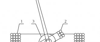
Balancing transformer
If the step-down transformer is loaded unevenly, phase imbalance will occur, which is a negatively influencing mechanism. The consequence of such operation and consumption of electrical receivers will be an increase in electricity consumption, and over time, failures and premature destruction of insulation. The safety of eating consumers will be at risk. In order to prevent this, it is necessary to balance the phases through the use of balun transformers.
As can be seen from the diagram, there is an additional winding that must withstand the rated current of one of the phases. It is connected to the break of the neutral conductor, which leads to good results, that is, the symmetrical generation of equal currents in the load.
Coffee capsule Nescafe Dolce Gusto Cappuccino, 3 packs of 16 capsules
1305 ₽ More details
Coffee capsules Nescafe Dolce Gusto Cappuccino, 8 servings (16 capsules)
435 ₽ More details
Samsung Galaxy S20 smartphones