Dmitry Levkin
- Design of a commutator DC motor
- Types of commutator motors With permanent magnets
- With field windings
- Basic parameters of a DC motor
- Characteristics of a brushed DC motor
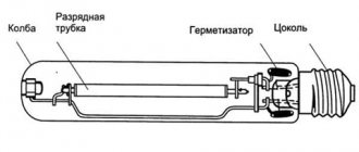
DC brushed motor
- a rotating direct current electrical machine that converts direct current electrical energy into mechanical energy, in which at least one of the windings involved in the main energy conversion process is connected to the collector.
What is a commutator motor and its features
The commutator is the part of the engine that comes into contact with the brushes. This unit ensures the transmission of electricity to the working part of the unit. A motor with at least one rotor winding connected to brushes and a commutator is called a commutator motor. Commutator electric motors are:
- direct current;
- alternating current;
- universal.
The commutator motor can be of direct or alternating current. There are universal models that can operate from any type of voltage source
The latter are universal, operating on both direct and alternating current. They remain popular, even though the presence of brushes is a negative point, since the brushes wear out and spark. This unit requires constant monitoring and maintenance. The advantages of commutator motors include the ability to smoothly adjust speed over a wide range and low cost.
Like other electric motors, a commutator motor consists of a stator and a rotor (often called an “armature”). Its distinctive feature is the presence of a collector unit on the shaft, through which power is transmitted to the machine. The design of DC and AC commutator motors are similar, but have certain differences, so let’s take a closer look at them separately.
General structure of commutator motors
Like any electric motor, a commutator motor converts electrical energy into mechanical energy. It consists of a stationary part - the stator and a moving part - the rotor. The stator houses the field windings, the rotor is responsible for transmitting the resulting mechanical energy. One of the components of the rotor is the shaft. On the one hand, a collector unit is placed on the shaft, with the help of which electrical energy is transmitted to the rotor windings.
Commutator motor: device
The stator consists of a housing that protects the motor components from damage. Magnetic poles are attached to the top and bottom of the housing. They are necessary to maintain magnetic flux between the stator and rotor.
Commutator motor rotor
The rotor of a commutator motor consists of a shaft onto which an assembled magnetic circuit is mounted. On the one hand, the collector unit is attached to the shaft, on the other, the fan blades. To ensure easy rotation and for fixation in the housing, bearings are placed on the shaft on both sides. For normal operation of an electric motor, the rotor must be perfectly balanced. Therefore, the production of this part is especially scrupulous.
Moving (rotating) part
Rotor winding
The rotor core is assembled from metal plates stamped from magnetic metal. The thickness of the plates is 0.35-0.5 mm, each of them is filled with a layer of dielectric varnish to get rid of stray currents. The plates have grooves along the outer edge into which turns of copper wire are then placed. These plates are placed on the shaft and secured to it, and a package of the required size is assembled. This system is a magnetic circuit.
This is what the rotor of a commutator motor looks like
Turns of copper winding wire are placed in the grooves of the magnetic circuit. The outputs of the windings are output to the collector unit, where they are switched.
How the collector unit works and how it works
The collector unit is worth considering in more detail. Otherwise, it is difficult to understand how the rotor rotates. The collector has a cylindrical shape and is made of copper plates (sometimes called lamellas), which are insulated from each other by mica or textolite spacers. There is no electrical contact with the axis of the shaft to which it is attached.
The collector has the form of a cylinder, which is made of copper plates. The plates are made in the form of sectors, separated by dielectric spacers
It turns out that the collector is assembled from copper sectors and, without winding, are not electrically connected to each other. The output of one rotor winding frame is attached to each collector plate. Two brushes are pressed against the plane of two opposite commutator frames. They fit tightly to the surface of the copper collector plate, which gives good contact. Potential is applied to these brushes, which is transmitted to that turn of the rotor winding that is connected to these plates.
Graphite brushes are pressed against the paired commutator plates
Since the rotor rotates at a certain speed, one pair of plates is replaced by another. Thus, voltage is transmitted to all rotor windings. At the same time, the fields arising one after another support the rotation of the rotor, “pushing” it in the desired direction.
Problem areas of the structure
Most often, malfunctions can occur in:
- bearings:
- brush commutator unit;
- layer of insulation of windings and wires.
Bearings
Their location is carried out at the edges of the rotor in such a way as to transmit the axial torque load as much as possible.
In ordinary household tools, they can be damaged for two main reasons:
- from incorrect load application:
- as a result of pollution.
Directions of effort
Bearings in household power tools are generally not designed to support lateral loads. From their frequent use, for example, when, when working with a drill, they do not load the end of the drill, but cut slot holes on its side, shaft beating is transmitted to the bearing mechanism, creating additional play of the balls in the cages.
Working in a polluted environment
The commutator motor has an air cooling system. The impeller, mounted on the rotor, takes air through special slots in the motor casing and drives it throughout the entire housing to remove excess heat from the heating windings. Warm currents are ejected through special holes.
If a dusty environment is created in the room, it will be sucked into the housing and penetrate the bearings and commutator-brush mechanism. There will be an abrasive effect on the parts that come into contact during rotation, their premature wear, as well as a violation of the electrical conductivity at the brush contacts.
Using a commutator motor for purposes other than its intended purpose, for example, collecting a flow of construction dust with a household vacuum cleaner instead of a construction one, is the most common cause of its breakdown.
Why do brushes spark?
Design features
When the engine is running, there is constant friction of the brushes against the contact plates of the commutator, which requires periodic inspection.
A slight layer of coal dust appears on the working surfaces of copper pads, as shown in the photograph. This is due to material consumption and brush wear.
This process always occurs when a commutator engine is running. Even with normal sliding of the brush, a slight break in the electrical current circuit is created. And this is always associated with sparking due to the occurrence of transient processes and the appearance of microscopic arcs. In addition, the windings have high inductive reactance.
Read also: Drawing of a CNC machine made of plywood
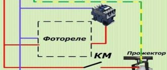
Therefore, a fully operational brush mechanism sparks during normal operation, which is not noticeable to the naked eye, but is felt by sensitive electronic devices: televisions, computers and other equipment. Noise suppression filters are always installed in their power supply circuit. An example is the electrical diagram of a microwave oven shown on the website with a highlighted green fragment.
Wear of brush material
The current-carrying part pressed against the collector plate is made of coal. Its volume wears out and its length decreases. This weakens the pressure force created by the expanding spring.
This process may or may not be taken into account in different brushed motor designs.
Rare samples
On the old 1960 engine shown as an example, the spring is compressed by screwing the dielectric cap.
The brush installation process is shown below.
Vacuum cleaner motor
The design of the brush mechanism described in the article about making a homemade trimmer has a screw for fixing the brush body.
Its installation is shown in the next photo. Please note that the brush itself was repeatedly ground down during long-term work and was replaced with a battery machined from a carbon electrode in the shape of the previous one.
When making brushes yourself, pay attention to the tightness of its entry into the socket and its perpendicular position to the shaft axis. If it is smaller, distortion will occur during operation. It will lead to excessive sparking and reduced engine life.
Therefore, it is advisable to use factory brushes from the manufacturer. There are other technical solutions to this issue.
How to check brush wear
The main method involves visual inspection. On the Internet you can find advice that recommends pressing the brush with a screwdriver while the engine is running and assessing the change in rotor speed.
This is a dangerous operation and should only be performed by trained and experienced personnel because:
- it is necessary to use protective equipment: work is performed under voltage;
- there is a possibility of creating a short circuit, because you will have to check both brushes in turn or simultaneously and use screwdrivers with insulated rods and tips.
If an external inspection shows that the length of the brush is greatly reduced or the working surface is chipped, then it simply needs to be replaced.
Contaminated collector
The formation of an excessive layer of coal dust with good conductive properties on the plates can cause them to short-circuit. It is necessary to remove it not only from the outer surface, but also from the spaces between them.
Graphite dust can be wiped off with a soft rag slightly moistened with alcohol or gasoline or removed with a thin wooden stick.
When the collector plates have lost their original shape and become grooved, they are restored using sandpaper with the finest grain on lathes. This is a complex operation that requires special equipment, but it can extend the life of the commutator motor.
Interturn short circuits in windings
Their formation on the stator or rotor sharply reduces the inductive reactance and leads to the appearance of additional sparks between different sections of the commutator and brushes. Additional overheating occurs.
Rotor winding
In some cases, the damaged section can be observed visually by a change in color. To perform electrical measurements, you will need an accurate ohmmeter. The testing technology is demonstrated in a video by the owner of altevaa TV “Checking the armature of a commutator motor.”
Repairing a damaged rotor winding is a complex operation. Sometimes it's easier to buy a new one.
Stator winding
The malfunction can be detected by measuring the active component of the electrical resistance using a bridge circuit for each half-winding. But this is also quite difficult.
Breakdown of the dielectric insulation layer
Let us briefly touch on the reasons for the formation of defects and the protective devices that must be used.
How malfunctions occur
The copper wires of the cores of all windings are covered with a layer of varnish, which can be damaged by:
- carelessly applied mechanical loads;
- at elevated temperatures.
These same factors cause insulation defects in PVC-coated supply wires.
As a result of these influences, the following electrical circuit malfunctions appear:
- interturn short circuit, which creates an additional path for leakage current to flow, which significantly reduces engine performance;
- short circuit that can burn out wires.
Protective devices
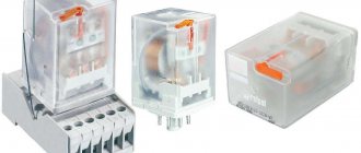
Thermal relay
The overheat protection function built into many commutator motors works automatically. When equipment is switched off from frequent operation, it is necessary to look for the cause of the temperature increase. Unfortunately, some users try to block the thermal relay. This leads to a breakdown that is difficult to repair.
Principle of operation
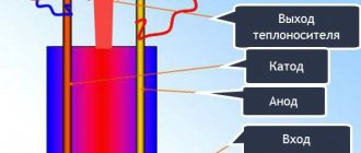
Now, after we have looked at the rotor structure, we can talk about how a commutator motor works. Actually, the principle of operation is no different from other motors; the rotor begins to rotate in a magnetic field due to the currents induced on it. But how exactly and why are these currents induced? To understand, we need to remember how electromotive force arises in a constant magnetic field. If a rectangular frame is inserted into the field of a permanent magnet, it begins to rotate under the influence of the current arising in it. The direction of rotation is determined by the gimlet rule. For a constant field, it says this: if you insert your right hand into the field so that the magnetic lines enter the palm, the outstretched fingers will indicate the direction of movement.
Illustration to explain the operating principle of a brushed DC motor
If you look at the structure of the rotor, we see that each winding represents such a frame. Only it consists not of one wire, but of several, but this does not change the essence. With the help of a collector unit, at some point in time, the winding is connected to the power supply, current flows through it and a magnetic field arises around the conductor. It interacts with the stator field. Depending on the type, there are permanent magnets there or a direct current also flows in the windings, generating its own magnetic field at the poles. The fields of the rotor and stator are designed so that when they interact, they “push” the rotor in the desired direction. Here, briefly and without much detail, is a description of the operation of a brushed DC motor.
The windings on the rotor are connected to the commutator plates. When the brushes come into contact with the plates, we get a closed circuit through which current flows
If you think about it a little, you can understand why a brushed motor allows you to easily and smoothly regulate speed. The more voltage is applied to the rotor windings, the more powerful the field the stator generates, the stronger their interaction and the faster the rotor spins, as it is pushed with greater force. If the voltage is reduced, the interaction is less, and so is the resulting rotation speed. So all you need to do is regulate the voltage, and this can even be a simple potentiometer (variable resistance).
How does a brushless motor work?
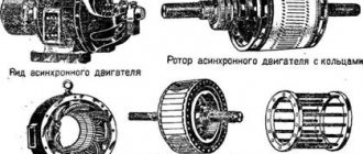
An alternating three-phase voltage is supplied, facilitating the flow of a 3-phase current system. The shift of the windings creates an MF. It induces an emf, which acts on the winding. The flowing current distorts the stator MF, which increases energy. This results in the formation of an electromagnetic force (EMF) that drives the rotor.
The formation of moving forces occurs when the rotation speed of the rotor and stator differs. In this regard, the VE operates asynchronously with the stator, which is why the installation received the name IM.
Modes
Using an additional motor switches the motor. An increase in the difference between the frequencies of the machine and the magnetic field changes the effective direction of the EMF. The same applies to the electromagnetic torque, which has become braking. Starting the generator mode involves operating a reactive power source - a magnetic field is formed. If there is no MF, then it is created by permanent magnets, active load capacitors, and induction.
An asynchronous type generator (ASG) involves the use of synchronous motors - compensators, static capacitors - in the network. Despite the ease of maintenance, GAT has found widespread use in rare cases. The equipment is installed in low-power wind generators, escalators, cranes, and elevators.
Idling occurs when there is no load on the shaft, for example, there is no gearbox or working manipulator. Based on the mode, the parameters of the current magnetization property and the parameters of power loss in the magnetic circuit are determined.
Electromagnetic brake
Varying the direction of the SE and MF changes the method of operation of the electromagnetic torque. Changing the path of rotation of the rotor and the field in the opposite direction places the EMF in the standard mode with the consumption of reactive power. But the EM is directed in the opposite direction of the load, which causes braking.
The operation mode is rarely used. Its negative side is the generation of heat, the volume of which the motor cannot dissipate. Prolonged and frequent use leads to breakdown of the power mechanism.
Management methods
Rheostatic - control of the frequency of the wind turbine by regulating the volume of resistance in the rotor circuit. Increases starting torque, increases the critical slip parameter. What else:
- frequency - a special converting element is installed that changes the rotor speed. The motor turns on through it;
- switch - a change in the winding circuit when starting an electric motor, which has a reducing effect on the starting current and torque;
- impulse impact - supply of another type of voltage;
- varying the number of poles is only relevant for mechanisms equipped with a squirrel-cage rotor;
- regulation of the amplitude of the supply voltage - notable for the regulation of the effective value, and the control vectors (VU) and excitation vectors are perpendicular (VP);
- phase technology – characterized by a phase shift between the VU and VP.
The method of changing the frequency and torque is selected taking into account the technical feasibility and feasibility of a certain method in a particular situation. The choice of methods increases the operating efficiency of machines of the above classes.
Advantages and disadvantages
As usual, let's start by listing the advantages. The advantages of commutator electric motors are:
- Simple device.
- High speed up to 10,000 rpm.
- Good torque even at low speeds.
- Low cost.
- Ability to adjust speed over a wide range.
- Low starting currents and loads.
Commutator motor diagram
Not bad qualities, but there are also disadvantages, and they are no less serious. The disadvantages of commutator electric motors are:
- High noise level during operation. Especially at high speeds. The brushes rub against the commutator, creating additional noise.
- Sparking of brushes, their wear.
- The need for frequent maintenance of the collector unit.
- Instability of indicators when the load changes.
- High failure rate due to the presence of a commutator and brushes, short service life of this unit.
In general, a commutator motor is a good choice, otherwise it would not be installed on household appliances. To be fair, it should be said that with normal performance quality, such engines operate for years. They can work for 10-15 years without problems.
What is the harm from inrush current?
Inrush current is a problem. This -
- overload of the supply network, leading to heating (up to the contacts burning out) and voltage sags;
- excessive wear, overload and overheating of the engine; some manufacturers indicate among the engine parameters the maximum number of starts per hour or per day - precisely because of overheating;
- wear and overload of the mechanical drive (bearings, gearboxes, belts), especially those with a large moment of inertia,
- interference caused by the activation of contactors, which are transmitted not only through wires, but also through an electromagnetic field,
- problems with technology - many processes cannot be started abruptly.
The starting current overloads everything, and the moment of starting becomes a burden to all participants in the process. It is at this critical moment that a “weak link” may appear. In addition, many power participants operating on this network experience problems - for example, light bulbs dim due to low voltage, and controllers can freeze due to strong interference.
And at the same time, starting current is a problem that cannot be avoided if you immediately supply the motor with rated power and do not use special methods.
So let's figure it out
Brushed DC motor with magnets
In brushed DC motors, a constant magnetic field is provided by:
- permanent magnets;
- field windings.
Magnets and windings are located on the stator housing, and most often at the top and bottom. If we talk about low-power motors, then commutator motors with permanent magnets are more popular. They are easier to manufacture, cheaper, and quickly respond to changes in voltage, which allows you to smoothly regulate the speed. The disadvantage of motors with permanent magnets is their low power, and also the fact that over time or when overheated, the magnets lose their properties and this leads to deterioration in the performance of the motor.
Commutator DC motor design
Such motors have low power, from a few to hundreds of watts. They are used in technology for which smooth speed control is important. These are usually children's toys, some types of household appliances (mainly fans). The disadvantage of a commutator motor with magnets is the gradual loss of power; the magnets become weaker over time, and the already small power drops. But recently, new magnetic alloys with high magnetic force have appeared, making it possible to create engines with high power.
With field windings
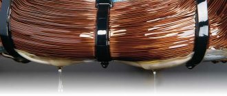
DC motors with excitation windings have found wider application. This type of engine powers cordless power tools: angle grinders, drills, screwdrivers, etc. The field windings are made of insulated copper wire (in a varnish sheath). The grooves in the pole pieces are used as a basis. Windings are wound on them as a base.
Commutator motor with winding excitation system
If we look at the design of a commutator motor, we see two unrelated devices, the rotor and the field windings. The characteristics and properties of the engine depend on the method of their connection. There are four ways to connect the rotor and field windings. These methods are called excitation methods. Here they are:
- Independent. This is only possible if the voltages on the field winding and the armature are unequal (this happens very rarely). If they are equal, a parallel excitation circuit is used.
- Parallel. Speed is well regulated, stable operation at low speeds, constant characteristics, independent of time. The disadvantages of this type of connection include instability of the motor when the inductor current drops below zero.
- Consistent. With this connection, you cannot turn on the motor with a shaft load below 25% of the nominal one. When there is no load, the rotation speed increases greatly, which can destroy the engine. Therefore, this type of connection is not used with a belt drive; if the belt breaks, the motor is destroyed. The series drive circuit has high torque at low speeds, but does not work very well at high speeds, making it difficult to control the speed.
- Mixed. Considered one of the best. Handles well, has plenty of low-end torque, and rarely gets out of control. Among the disadvantages is the highest price compared to other types.
Methods for connecting field windings
Brushed DC motors can have an efficiency from 8-10% to 85-88%. Depends on the connection type. But high-performance ones are characterized by high speeds (thousands of revolutions per minute, less often hundreds) and low torque, so they are ideal for fans. For any other equipment, low-speed models with low efficiency are used, or a gearbox is added to productive models; no other solution has yet been found.
Universal brushed motors
Despite the fact that the collector unit can be called the weakest point of the electric motor, such models are widely used. All thanks to the low price and ease of speed control. AC commutator motors are found in almost any household appliance, both large and small. Mixers, blenders, coffee grinders, hair dryers, even washing machines (drum drive).
Universal commutator motor operates on direct and alternating voltage
In structure, universal commutator motors do not differ from DC models with field windings. There is certainly a difference, but it is not in the device, but in the details:
- The excitation circuit is always sequential.
- The magnetic systems of the rotor and stator to compensate for magnetic losses are made of the laminated type (a single system without continuous cuts).
- The field winding consists of several sections. This is necessary so that the operating modes on direct and alternating voltage are similar.
The operation of universal-type commutator electric motors is based on the fact that if you simultaneously (or almost simultaneously) change the polarity of the power supply on the stator and rotor windings, the direction of the resulting torque will remain the same. With a series drive circuit, the polarity changes with very little delay. So the direction of rotation of the rotor remains the same.
Advantages and disadvantages
Although universal commutator motors are actively used, they have serious disadvantages:
- Lower efficiency when operating on alternating current (when compared with operating on direct current of the same voltage).
- Strong sparking of the collector unit on alternating current.
- They create radio interference.
- Increased noise level during operation.
In many models of construction equipment
But all these disadvantages are offset by the fact that at a supply voltage frequency of 50 Hz they can rotate at a speed of 9000-10000 rpm. Compared to synchronous and asynchronous motors, this is a lot; their maximum speed is 3000 rpm. This is what led to the use of this type of motor in household appliances. But they are gradually being replaced by modern brushless motors. With the development of semiconductors, their production and management are becoming cheaper and easier.
Soft start process
A soft start of the compressor with minimal time is ensured through a multi-stage starting process. The number of steps can be chosen arbitrarily. The optimal number of cyclic stages is considered to be no more than five. With a sharp decrease in resistance, a significant surge in Is occurs ,
which can lead to commutation failure. To ensure starting, one of the permissible critical values of the starting torque is taken into account - maximum or minimum, that is:
Mn min = (1.2–1.5) Ms; Mp max ≤ Mdop.
Each stage has its own characteristic. The soft start of the commutator electric drive is carried out as follows. When power is supplied to the CD, the torque surge reaches the permissible maximum. Starts gaining speed according to the first characteristic. After reaching the minimum torque value, the machine switches, part of the electrical resistance is removed from the armature circuit (shunted).
At the next cyclic stage, the torque value is again increased to the maximum parameter, and when it is reduced to a minimum, the electric motor switches again, and the next part of the resistance is shunted. This process is repeated until the electric drive accelerates to operating speed. In order to prevent exceeding permissible torque limits, it is necessary to correctly calculate the electrical resistance.
Starting and controlling electric drives in production environments is often automated. Switching of rheostat stages is carried out by contactors, which with their contacts, as the motor accelerates, bypass the rheostat elements when switching resistor stages. To control the speed of the electric drive, frequency converters and servos are used, and for complex drive systems, logical programmable controllers are used. The choice of one control method or another depends on the task that the electric drive must perform.