The design and technical construction of synchronous electric motors determines the peculiarities of their functioning and use. One of the main differences between machines of this type is the impossibility of starting them when connected directly to the power supply.
Synchronous motors, like asynchronous machines, are AC electric drives that convert electricity into mechanical movement of a shaft. Due to the different operating principle, there are a number of mandatory conditions for correct operation and operation. One of these requirements is the startup of electrical equipment.
Purpose and design
Before moving on to a detailed consideration of the process of starting a synchronous motor (SM), it would be useful to briefly repeat the main aspects of the theory. What is SD, how its elements interact, what types there are and why this type of electric drive is called that. After this, you can consider starting methods.
A synchronous motor (SM) is an electrical equipment whose operation is provided by an electromotive force arising from the interaction of the magnetic fields of the stator and rotor mechanism. This principle is fundamental for the design of electric motors of various types. Despite the uniform approach, drive equipment has its differences.
The main feature is the design of the moving mechanism and the principle of its rotation. Depending on the required power, the rotor can:
- contain permanent magnets and be the initiator of magnetoelectric excitation;
- represent electromagnets that initiate electromagnetic excitation.
The first option is used for low-power electric machines. Permanent magnets are made of hard magnetic materials capable of maintaining a state of magnetization. They can have either a built-in or surface location on the rotor.
The second type of design of the rotor unit involves the installation of a ferromagnetic core with an electrical winding. When energized, such a system is a source of magnetic flux that interacts with the stator field.
The definition of synchronism, that is, sameness, is based on the equality of the rotor speed and the stator magnetic field. This is the key difference in the operating principle of electrical equipment, which determines its technical capabilities, operating features and scope of application. The same factor directly affects the starting of synchronous motors.
Varieties
In modern industry and household appliances, synchronous electric motors are used to solve a wide variety of problems. As a result, their design features also differ significantly. In practice, there are several criteria by which types of synchronous units are divided. In accordance with GOST 16264.2-85 they can be divided according to the following technical characteristics:
- supply voltage;
- operating voltage frequency;
- number of revolutions.
Depending on the method of obtaining the rotor field, the following types of synchronous electric motors are distinguished:
- With an excitation winding on the rotor - the synchronizing force is created by supplying power from the converter.
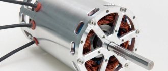
- With a magnetic rotor - a permanent magnet is installed on the shaft, performing the same functions as the field winding, but without the need for recharge (see Figure 6).
Rice.
6. Synchronous electric motor with permanent magnets With a reluctance rotor - the design is made in such a way that refraction of magnetic lines occurs in its core, causing the entire structure to move (see Figure 7). Under the influence of a force field, the transverse and longitudinal components in the rotor are not equal, due to which the plates rotate following the field.
Rice. 7. Example of a jet rotor
Depending on the presence of poles, all synchronous electric motors can be divided into:
- salient-pole - the design clearly shows separate poles with windings, used for low speeds;
- non-salient pole - the pole is not highlighted, such models are installed for high speeds;
Depending on the location of the working windings, a distinction is made between direct (on the stator) and reverse (working windings on the rotor).
Launch Aspects
The operating principle of the SD imposes a number of requirements, without which not only a smooth start, but also the start of the synchronous electric motor itself is impossible. In an LED, a rotating field is created by a three-phase current in the stator circuits. In this case, the power developed on the electric motor shaft is compensated by the power coming from the supply network. That is, the interaction of the stator device current with the field of the rotor mechanism initiates the occurrence of torque.
As already mentioned, the speeds of the rotor and the fields of the stator assembly are synchronous. If a difference occurs during a certain period of time, the poles of the rotor-stator mechanism will be located opposite each other. As a result, the magnetic connection will be disrupted, since like poles will repel each other. The rotor will stop experiencing torque and stop. Therefore, ensuring simultaneous rotation for a synchronous motor is a fundamental condition for its operation.
But self-startup with a direct network connection is not possible. The rotor mechanism, due to its inertia, is not able to quickly reach the frequency of the stator field, while the rotation of the latter is established simultaneously with the connection to the power supply network. Therefore, a stable connection creating torque does not arise between the poles of the excited rotor assembly and the rotating field.
Advantages and disadvantages
Structurally, synchronous motors are more complex than asynchronous ones, but they have a number of advantages:
- The operation of synchronous electric motors is less dependent on fluctuations in the supply voltage.
- Compared to asynchronous ones, they have higher efficiency and better mechanical characteristics with smaller dimensions.
- The rotation speed does not depend on the load. That is, load fluctuations in the operating range do not affect the speed.
- They can work with significant overloads on the shaft. If short-term peak overloads occur, increasing the current in the excitation winding compensates for these overloads.
- With an optimally selected excitation current mode, electric motors do not consume or supply reactive energy to the network, i.e. cosϕ is equal to unity. Engines operating with overexcitation are capable of generating reactive energy. This allows them to be used not only as engines, but also as compensators. If reactive energy generation is required, increased voltage is applied to the field winding.
Despite all the positive qualities of synchronous electric motors, they have a significant drawback - the difficulty of putting them into operation. They have no starting torque. Special equipment is required to start. This limited the use of such engines for a long time.
Inclusion methods
Based on the fact that direct starting is impossible, the inclusion of a synchronous motor in the work process is carried out with the implementation of additional measures. Regardless of the methods of starting an electric drive, the essence of each is to first set the moving part in motion at speeds close to the frequency of the main field.
When starting, the flux moves so slowly relative to the magnetic centers of the rotating shaft that when the exciting electrical winding is connected to the power source, a magnetic connection is established between the rotor poles and the stator field. It is this that ensures the occurrence of the same electromagnetic moment. Under its action, the electric motor shaft is pulled into synchronism.
There are several ways to start synchronous motors. Three of them have received practical application:
- through auxiliary electrical equipment;
- asynchronous, including autotransformer and reactor starting;
- frequency starting of a synchronous motor.
Each synchronous motor starting scheme has its own advantages and disadvantages regarding the complexity of the design and technical design, financial costs, and dimensions of the drive units. Therefore, where, for example, a reactor start-up would be optimal, it would be wiser not to use the more expensive frequency start-up. Which method is optimal depends on many factors.
Starting and stopping a synchronous motor must be carried out in compliance with a certain sequence of actions and conditions. Therefore, to reduce the risk of failure of the electric drive at the start, a system is provided to protect the synchronous motor from prolonged activation. And at the stopping stage, the following algorithm is observed:
- reduce the excitation current to a value equal to the minimum current parameters of the stator;
- turn off the stator assembly;
- open the exciting electrical circuit.
Deviation from this sequence is fraught with a jump in current values in the stator, overvoltages and, as a result, a violation of the integrity of the insulation.
Scope of application
Synchronous motors are more expensive than asynchronous motors, and they also require an additional source of direct current excitation - this partly reduces the range of applications of this type of electrical machines. However, synchronous electric motors are used to drive mechanisms where overloads are possible and precise maintenance of stable speed is required.
At the same time, they are most often used in the area of high power - hundreds of kilowatts and units of megawatts, and, at the same time, starting and stopping occur quite rarely, that is, the machines operate around the clock for a long time
This application is due to the fact that synchronous machines operate with cosPhi close to 1, and can supply reactive power to the network, as a result of which the power factor of the network is improved and its consumption is reduced, which is important for enterprises
Starting with auxiliary equipment
Starting up a synchronous motor with an additional drive is similar to the process of turning on a synchronous generator for parallel operation. In fact, the launch is carried out using an auxiliary (acceleration) electric motor. In this case, the shaft of the excited electric motor is set into rotation, accelerates to the required frequency and is connected to the electrical network through a synchronizing device. The auxiliary drive is then switched off.
This starting method involves the use of a machine with significantly lower power, amounting to 5-15% of the power of the SD. The use of a starting electric drive of greater load-bearing capacity, sufficient to accelerate a loaded motor, is irrational from the point of view of bulkiness and efficiency. Therefore, using this method, electric motors are started either without load or at its insignificant value.
The process of starting a synchronous motor is performed by an asynchronous motor with a wound rotor with two fewer poles compared to the number of poles of an SD. This is necessary to accelerate the shaft of the driven mechanism to the required speed. The speed of an asynchronous machine is controlled by an adjusting rheostat. In practice, this starting method is used only for powerful machines, because This type of drive for motors, for example, 6 kV, is not rational.
Applying resistance at start
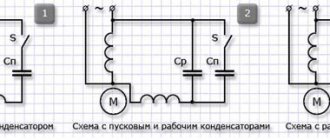
The method is applicable for asynchronous motors connected to a single-phase network and having a primary additional winding with a squirrel-cage rotor. This is the name given to a split-phase motor, the electrical circuit of which has a high active resistance.
To start a motor powered from a single-phase network, a starting resistor is needed, connected in series with the additional winding. Then the phase shift is 30 degrees. This is enough for overclocking. Below is a diagram according to which an ohmic phase shift is achieved.
Instead of a resistor, you can use an additional winding of high resistance but low inductance. In this case, the winding has few turns, which are made from wire of a smaller cross-section, in contrast to what is used for working winding.
In Russia, motors come off the assembly line connected to a single-phase network, equipped with a phase shift resistor. Their power varies in the range of 18-600 W. The motors are designed for networks with a voltage of 127, 220 or 380 Volts and alternating current with a frequency of 50 Hz.
Asynchronous launch
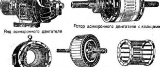
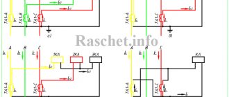
The most common starting method is the method using starting short-circuited (damper) electrical conductors located in the grooves of the pole elements. The electrical windings are made in the form of brass or metal rods, which are closed on both sides with copper rings (position “b” in the figure).
When starting, the field winding (OB) is closed to a resistor, and the stator circuit is connected to the power supply network (position “a”). The rotating field of the stator device induces an EMF in the rods, as a result of which currents arise in them. When they interact with the magnetic flux of the stator, an electromagnetic force Fem acts on each rod, causing rotation.
After reaching the pre-synchronous speed, the OB is connected to a constant power source. The resulting torque accelerates the electric motor rotor to synchronism. At this time, the EMF is no longer induced in the starting circuit, so the asynchronous torque is zero. Then the damper short-circuit electrical winding performs only a calming function, limiting possible vibrations of the shaft.
The process of starting a synchronous motor must be carried out with a closed OB to an active electrical resistance, the value of which should be approximately ten times greater than the electrical resistance of the exciting electrical circuit. In this case, short-circuiting the OB during the acceleration period is undesirable, since a closed circuit is formed on the rotor, creating an asynchronous torque. At half the presynchronous speed, the torque turns into a braking torque and a certain braking of the synchronous motor occurs. There is a so-called “dip” in the torque value, which significantly reduces the starting qualities of the SD.
There are other limitations and features of starting using short-circuit windings. This is due to the occurrence of a large inrush current at the start. In this regard, LEDs are connected to the AC network only with its appropriate power, which can withstand five- and seven-fold current loads relative to the rated values of the electric motor. If there is insufficient power in the electrical network to limit current surges, switching on is carried out using a reduced voltage. Such starting methods are called autotransformer or reactor starting.
Reactors and autotransformers provide a forced reduction in the rate of current rise and its magnitude in the working windings. Reactor starting involves the installation of reactors in each power supply circuit of the phase electric circuit of the LED. In this regard, the current values do not increase abruptly and the start-up is smoother than a direct start. When the electrical equipment accelerates to pre-synchronous speed, switch K1 removes the inductive component from the electrical circuit and the electric drive operates in normal mode.
DIRECT START OF AN INDUCTION MOTOR
As mentioned above, direct connection of the winding of an asynchronous motor can only be used at low power. In this case, the starting current exceeds the rated current by 5-7 times, which is not a problem for switching equipment and electrical wiring.
The main problem with direct starting is connecting several electric motors to a low-power substation or generator.
Connecting a new electric motor to the network can cause such a strong voltage drop that the already running motors will stop, and the new motor will not have enough starting torque to get going.
The starting current of an asynchronous motor reaches its maximum value at the moment of switching on and gradually decreases to the nominal value as the rotor spins up.
Therefore, to reduce network overload time, the induction motor should be started with a minimum load, if possible.
Powerful lathes and guillotines for cutting metal do not have friction clutches, and all their rotating mechanisms spin up when the electric motor is turned on.
In this case, long-term voltage sags have to be directly included in the power supply designed for them.
Frequency switching
Frequency starting of a synchronous motor is performed using reduced voltage with a low current frequency. This is possible if there is a power source capable of adjusting the frequency to the required parameters. In this case, the speed of the magnetic flux will also be low, and the poles of the rotor assembly will rotate with it.
As the speeds become the same, the starting frequency of the supply current is gradually increased, accelerating the rotor to the nominal value. This starting method is considered soft, providing a smooth start. Its disadvantage is the need for a power source of adjustable frequency and voltage.
Modern frequency starting of a synchronous motor is implemented on the basis of circuits based on semiconductor elements - thyristor converters. They reduce the nature of the voltage change, practically without changing the effective value. This method of starting in automation systems provides a reduction in acceleration time, which has a positive effect on the performance of automated systems, but at the same time requires a more complex switching circuit.
Operating modes
Most electric machines have a reversible function, and synchronous units are no exception. They can also be used as an electric drive or as a generator to produce electricity. Both modes differ in the way they influence the electric machine - applying voltage to the working windings or driving the rotor due to mechanical force.
Generator mode
Synchronous generators are used to produce electricity into the network. In most cases, electric machines with phase windings on the stator are used for this purpose, which significantly simplifies the process of collecting power and its further transfer to the network. Physically, generation occurs when exposed to the electromagnetic field of the excitation winding of a synchronous generator with stator windings. The power lines alternately cross the phase turns and induce mutual induction emf in them, as a result of which voltage appears at the terminal terminals.
The frequency of the resulting voltage directly depends on the shaft rotation speed and is calculated by the formula:
f = (n*p)/60 ,
where n is the shaft rotation speed, measured in revolutions per minute, p is the number of pole pairs.
Synchronous compensator
Due to the physical characteristics of the synchronous electric motor, when the device is idling, it consumes reactive power from the network, which can significantly improve the cosφ of the system, practically bringing it closer to 1. In practice, the synchronous compensator mode is used both to improve the power factor and to stabilize the network voltage parameters.
Motor mode
In a synchronous machine, the motor mode is carried out when a three-phase operating voltage is supplied to the armature windings. After which the electromagnetic field of the armature begins to push the magnetic field of the rotor, and the shaft begins to rotate. However, in practice, the propulsion mode is not so simple, since powerful units cannot independently gain the necessary speed resource. Therefore, during startup, special methods and connection diagrams are used.
Motor protection at start
The synchronous motor delay protection system is designed to reduce the negative impact of excessively high torque that occurs when the motor starts up. The reason for the occurrence of large torque values is insufficient excitation or its absence in the electric motor during start. The protection scheme provides for the use of:
- zero current relay, which controls the current load during excitation;
- a time relay that counts the duration of a normal start.
The protection system for a synchronous motor against prolonged starting is triggered when the excitation current in the electric motor has not reached a sufficient level within the time corresponding to a normal start. In this case, the protective system against a delayed start interrupts the switching process by turning off the power to the stator. Such a protection circuit belongs to the category of special functions of electric drives, simultaneously with protection against electrical winding breakage, overspeed, overvoltage, etc.
Design of synchronous electric machines with permanent magnets
The PMSM consists of a moving (rotor) and a stationary (stator) part. The rotor design varies:
- On installing magnets. They can be placed on the surface (SPMSM) or inside (IPMSM) of the rotating assembly. Rotors with built-in magnets are used in motors operating under significant shaft loads and high speeds. The cost of such rotors is significantly higher.
- By design (salient-pole and non-salient-pole rotors). The latter have equal inductance along the axes of the horizontal plane. Salient pole rotors have different inductance ratios.
Permanent magnets are made from ferrites, rare earth alloys and other materials with high coercivity.
The stator of synchronous electrical machines consists of a core made of electrical steel sheets and a two- or three-phase winding. There are stators with distributed and concentrated windings. The first has different positions of the turns in the magnetic field. The turns in concentrated windings have the same position.
Trapezoidal control
This scheme is used for valve motors. The design of such machines is no different from PMSM. Their main feature is the principle of nutrition. A trapezoidal voltage is applied to the HP stator windings. Phase switching is carried out depending on the angle of rotation of the rotor.
HP control circuits are also available with and without a sensor. Hall sensors are usually used as a feedback device. The greater their number, the more accurately the rotation angle is determined. For example, 3 Hall sensors allow you to determine the rotor position with an accuracy of ±300. Sensorless control systems determine positions based on previously known functions. Such schemes are used to solve simple problems.
Permanent magnet synchronous motor control
Synchronous machines are controlled using frequency converters and servo controllers. There are several management principles for PSDM. The choice of circuit is made based on the requirements for the electric drive and economic feasibility. The most common schemes for implementing control of a synchronous electric drive:
Scalar
This scheme is simple and inexpensive. At low rotation speeds and variable load on the shaft, this method is not suitable. When the load exceeds the maximum torque on the shaft, the electric machine leaves the synchronous mode and becomes uncontrollable.
Vector
Vector control of a permanent magnet synchronous motor is implemented in 3 ways:
- Field-oriented control with position sensor. The first scheme allows for smooth regulation of the rotation speed and torque on the shaft, as well as setting the exact position of the rotor. Optical, magnetic and magnetoresistive devices, sine-cosine rotating transformers, inductive encoders and other devices are used as sensors. Such circuits require controllers and fine tuning. Their cost is quite high. It makes sense to use vector control circuits only in ambitious electric drives of high-precision machine tools, dispensers, etc.
- Field-oriented control of synchronous machines without feedback sensor. The principle of determining the angle of rotation of the rotor with this method is based on the generation of counter-EMF by an electric motor during rotation. Calculating its value makes it possible to determine the position of the rotor in a stationary coordinate system. Sensorless control is not suitable for low rotation speeds because the back EMF is too small and does not exceed the level of normal electromagnetic noise. In addition, when the rotor is stationary, no back EMF is generated at all. A circuit without a sensor allows you to change the characteristics of a PMSM electric drive with a salient pole rotor. When using other types of synchronous machines, the adjustment range is greatly reduced. This circuit requires a processor control unit.
- Direct torque control. This scheme provides good dynamic characteristics of the electric drive and a wide adjustment range. Its use is limited by the significant error in determining the rotor position and high pulsations of the stator current and torque on the shaft. In addition, direct control creates a high computational load; such schemes require a powerful processor device.