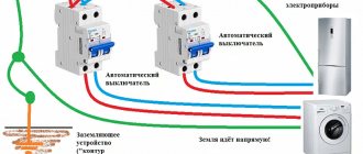
Grounding is the intentional creation of contact between an electrical device connected to the electrical network and a grounding device. It is designed to divert current in the event of a break in the housing, which appears on the metal parts of household appliances when an accident occurs. Grounding automatically cuts off the voltage due to the operation of an RCD (residual current device).
When the equipment is protected in this way, then in the event of any human contact with household appliances, the current remaining on the equipment will no longer be dangerous. If the equipment was not grounded during installation, the current passes through the body of the person who touches it. Although this residual tension will be noticeable, it will not be dangerous.
Residual tension is noticeable, but not dangerous. Source yandex.ru
Why is the TN-C system obsolete?
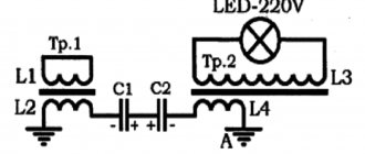
Much of modern technology uses switching power supplies.
These devices have filters against RF interference. These are small capacitors that connect the circuit to the metal case and the ground pin of the plug. Interference coming from the electrical network or occurring during the operation of electrical equipment through the capacitor and ground wire “goes into the ground” and does not disrupt the operation of devices connected to the power supply.
Under normal conditions, the current passing through the filter is not sufficient to trip the RCD or electrocute a person, but if this capacitor breaks down, the housing is connected to a 220V network. This situation is not dangerous if there is a grounding system that complies with the requirements of the PUE, but can lead to electrical injury if it is absent or the TN-C system is used.
The situation of a break in the neutral wire “N” is also dangerous. In this case, the housing will be energized through the “phase-electrical device-zero-grounding-body” circuit.
A similar situation occurs when a leak occurs in a washing machine or dishwasher or a heating element burns out in a boiler.
| The main disadvantage of the TN-C system is the appearance of a dangerous potential on grounded equipment housings when the PEN conductor burns out. That is, in cases of PEN conductor breakage, grounding (grounding) loses its protective properties. |
Dangerous grounding methods
In order to protect themselves and their family members from electric shock, some “experts” lay the grounding line themselves. Various options are used for this:
- Connection to central heating radiators or water pipes. This is dangerous because if there is a small leak, current will begin to flow through the pipes, causing rapid corrosion, and plumbers may suffer electrical injury during repairs.
- Connection in the socket of the neutral and ground contact. This is not grounding, but grounding. In the PUE clause 1.7.50, grounding is not included among the means that protect against electric shock.
- Connecting the PE protective conductor to the electrical panel housing located on the floor. This option is better than the previous ones, but the quality of the connection between the PEN wire itself and the shield body is unknown. In addition, the junction of the “PEN”, “N” and “PE” wires must be grounded.
In addition, it is not known whether the PEN conductor in the floor panel is grounded at all. For example, one can imagine a situation where, with such a “grounding scheme,” the neutral wire N breaks, and then all the grounded housings of devices in the apartment through this additional PE conductor will be energized.
Moreover, if you look at it, such a connection is not grounding, but grounding.
In addition to various options for independent connection to the “PEN” wire, it is possible to install a grounding loop from steel corners, pins and pipes buried below the soil freezing level. A wire is connected to these corners, brought into the apartment and connected to sockets. In this case, there is a danger of this wire breaking or oxidizing at the contact point located on the street.
Important! The grounding loop, carried out in accordance with all the rules, is connected by electric welding to the metal elements of the building structure and is subject to regular inspection. The only reliable protection against electric shock is the installation of TN-CS or TN-S grounding systems
In this case, if the insulation between the grounded body of the electrical device and the live parts is broken, a short circuit will occur along the “live parts-body-grounding” circuit, the current through the circuit breaker will increase and the machine will turn off the power to the installation
The only reliable protection against electric shock is the installation of TN-CS or TN-S grounding systems. In this case, if the insulation between the grounded body of the electrical device and the live parts is broken, a short circuit will occur along the “live parts-body-grounding” circuit, the current through the circuit breaker will increase and the machine will turn off the power to the installation.
It is advisable to additionally connect an RCD to the grounding system in the electrical panel. This device will turn off the power supply if the insulation is broken and leakage current appears, but there is no short circuit.
Similar materials on the site:
- Types of grounding systems according to the PUE
- How to perform zeroing in electrical installations
Grounding. What to do if the supply line is two-wire
In this article we will examine in detail the question of how to correctly connect an RCD (Residual Current Device) in a two-wire power supply system.
In our work, we often have to deal with a situation where electrical equipment at a facility is not completely grounded, or is not grounded correctly.
Most often this occurs in apartments, residential buildings, offices and shops that are located in old buildings where the wiring has not been changed for decades.
At some facilities, all wiring is made with two-wire wires (or four-wire for three-phase consumers), that is, there is no third (or fifth for three-phase networks) protective grounding conductor. In this case, everything is immediately clear. Verdict - the equipment is not grounded.
In other cases, internal wiring is done as required with three-core cables (five-core for three-phase equipment) and all electrical installations and electrical installations (sockets) are connected to a protective grounding conductor.
Test method
Before checking the serviceability of the grounding, you should determine the neutral and phase wires using an indicator screwdriver. After contact with one terminal, the light in the screwdriver lights up - this is phase, if it does not light up - zero. The presence of grounding, even with a three-wire wire, must be checked using simple methods: using a multimeter or a tester.
Checking with a multimeter
- turn on the power supply in the room (house) at the distribution board;
- measure the voltage in the socket by setting one probe to phase and the second to zero;
- move the contact sensor probe from zero to the grounding conductor (PE);
- check the tester's readings; if they have remained virtually unchanged, it means the grounding system is in order; if the readings are at zero, the system is not working.
Checking with a control light
To build a device called a “control,” you need to take a light bulb with a socket and connect two copper wires to it. In this case, the contacts of such a tester must be isolated between all elements. Testing with a test light is carried out in the same way as with a multimeter: one probe is connected to zero, the second to phase. Then the probe is moved from zero to the ground connection.
If the wiring does not have color recognition, you can determine the phase and zero in this way: attach one limit switch to the ground terminal, and the second one alternately to the first and second connections. The phase is located where the light source will light up. If the light does not light, it means that the PE circuit is not functioning.
In the case when the lamp does not light when the phase and neutral are connected, you need to check the contacts of the device, and also whether the lamp has burned out and whether there is power in the distribution board. Sometimes the reason the lamp does not light up is that there is a break in the neutral or phase circuit.
When research with devices does not show an absolute guarantee of connection, it is necessary to open the outlet and check the conductors. To do this correctly, you need to follow the instructions:
- Check the voltage by plugging in one of the appliances (table lamp, iron, etc.). In this case, you must not touch the grounding contact.
- Turn off the power at the distribution panel and remove the plug from the socket.
- Remove the socket cover and check the tightness of the wires, and also see what the ground pin is connected to. If it is connected to one of the socket terminals, it is grounded. Connecting to a separate wire indicates that grounding is being used. Lack of connection is a factor of lack of grounding.
- Place the cover in place, secure it and turn on the machine on the panel.
When working with the electrical network, we must not forget about safety rules. Be sure to check the serviceability of all devices. Do not touch the conductor with wet hands or stand on a wet floor. You cannot make a PE loop between the grounding contact and the neutral terminal, this can lead to a fire after the neutral conductor breaks. The best option is to call a professional electrician.
You should definitely check the PE circuit if: you hear noise while playing music or feel slight electric shocks when using household appliances such as a kettle, water heater, washing machine or dishwasher. Such factors are a sign that the PE system is not functioning at all or is working poorly.
What is the difference between “zero” and “ground” in electrical engineering?
Some electricians with experience cannot always answer correctly the question “what will happen if the ground is used instead of zero” or what is the difference between grounding and grounding. It is important to understand this in order to avoid mistakes in your work.
If grounding is done, the body of the equipment is connected to the neutral conductor. When grounding is done, the body of the electrical device is connected to a grounded circuit consisting of metal pins driven into the ground.
Grounded circuit - metal pins driven into the ground Source yandex.ru
Features of installing a grounded outlet
The connection diagram for a grounded outlet does not involve any complex manipulations. Anyone can cope with this. It is enough to familiarize yourself with the theoretical part and be careful during installation.
Before installing a grounded outlet, the type of wiring is determined. To do this, the old socket is dismantled. If two wires are connected, there is no grounding, only phase and neutral (zero phase) are available.
When purchasing a socket, the quality of the product is taken into account and preference is given to a manufacturer that has proven itself in the market. Its body must be without damage. So-called “internal” sockets are suitable for the home - they are built in when installed in a wall recess. The recommended rated breaking current for a home outlet is from 30 to 100 milliamps. Information about the rating can be read on the back of the socket. Russian samples are usually rated at 10 or 6.3A; foreign - at 10 or 16A.
Particular attention is paid to the size of the holes and the distance between them. European samples have both a larger diameter and a larger distance
If you use exclusively domestic appliances at home, it is better to buy sockets that are also domestic.
The plug can be removed from a correctly selected socket with little effort!
There is a wide variety of grounded sockets on the market:
- There are samples with overload protection - there is a built-in fuse inside, which blows out in the event of a short circuit.
- With protection against current leakage - a special device turns off the socket if a leak is detected. The socket is ideal for a child's room! As soon as the baby puts something into the socket, the protection will immediately work.
- With overvoltage protection - automatically turns off when there is a power surge, suitable for connecting expensive devices.
- With mechanical protection – special curtains protect against touching the contacts.
- With lightning protection – for regions with strong thunderstorm activity.
- For powerful devices - designed for a current of 20 amperes or more. Always sold with a special plug.
- Universal – complete with connectors for different types of plugs.
The socket box is selected based on the type of wall. The socket box is fixed inside the wall, in a special recess.
Drywall boxes are used for drywall, wood, and plastic. And for brick, concrete, foam concrete - concrete boxes. They are fixed with gypsum or alabaster mortar.
Attention! The working body of the product must be of high quality - made of ceramics. The socket contacts are made of good metal (not foil!)
It is desirable to have a screw clamp - the wires are inserted between two plates and pressed with a screw, which ensures reliable fastening of the contacts and prevents them from loosening during operation.
Poor contact at the connection point of the conductors causes an increase in current, heating the cables, which can cause an emergency situation
Therefore, it is very important to ensure the correct connection of the wires in the junction box when carrying out electrical work on a home network.
The choice of distribution boxes must be made based on their design and purpose, which is discussed in a separate article.
Before installation, turn off the power to the electrical panel. The wires are routed to the sides. The phase is determined by an electrical tester (probe). Usually the wires differ in color. Yellow-green insulation indicates grounding. If the wires are the same color, a tester will help you find the phase.
Wiring connection rules. phase - on the right, neutral - on the left, grounding - to the top or central terminal of the socket.
Is it possible to ground sockets to zero?
Question for experienced electricians. At the dacha, when replacing an outlet, I discovered a wire inside it running from the “zero” to the grounding contact on the same outlet; I discovered exactly the same “invention” when replacing a 5 kW instantaneous water heater - is this acceptable in the absence of proper grounding? What does this mean, how will it manifest itself in the event of a problem in the electrical network?
No you can not. There is a 3rd ground wire for this purpose. If it is not in the home wiring, then each outlet or device must be grounded. “0” is the 4th or 2nd wire in the power transmission line and is connected at the substation to the solidly grounded neutral of the transformer windings, which are connected by a “star”.
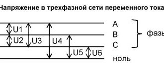
The consequences of “grounding” to “0” (or zeroing) can be disastrous. Imagine a situation when, during a thunderstorm or other phenomena and events, a phase wire breaks and falls to neutral! You already have in your house either two wires with the same phase, worse if from the neighboring one (AB, BC, CA), then this is 380! Then all the devices connected to the network will be in trouble, not to mention electrocuting people. How to make a proper grounding circuit yourself - write, I will answer.
Installation of a built-in socket with grounding
At the first stage, a socket box is installed, which can be represented by models for plasterboard or concrete walls. The room is de-energized, after which the following actions are performed:
- the socket box is placed in a standard size hole made in advance in the wall;
- structures for plasterboard walls are fastened with self-tapping screws and plastic clips, and for concrete, a freezing method is used using alabaster or other plaster mixtures;
- the insulating part of the wires coming out of the socket box is stripped one centimeter;
- unscrew the screw and remove the cover from the base;
- the wires are screwed onto the terminals.
The order of connections must be strictly observed. First, the grounding connection is made, then the “zero” and the remaining “phase” are connected.
The grooves in the wall for the electrical wire are made with a hammer drill and have a depth and width of 2.5 cm.
Wire marking by color
Indeed, the easiest way to determine the phase, neutral and ground of an electrical wire is to look at the color marking and compare it with the accepted standard. Each core in modern wires used in electrical wiring and electrical equipment has an individual color. Knowing which color of cores corresponds to which function (phase, neutral or grounding), you can easily carry out further installation.
Quite often, this is quite sufficient, especially in cases where the installation is carried out in new buildings or places with fairly new electrical wiring, made by professional, competent electricians in accordance with all modern rules and standards.
According to this standard for residential electrical networks:
Working zero (neutral or zero) – Blue wire or blue-white
Protective zero (earth or grounding) – yellow-green wire
Phase – All other colors including black, white, brown, red, etc.
Now, knowing the standard for color marking of wires, you can easily determine which wire performs which function. This applies to most cases, the exception may be wires suitable for switches, switches, etc., due to the fundamentally different operating scheme of this electrical equipment.
Differences between grounding and grounding
Grounding and grounding methods have different protective effects. Grounding ensures instantaneous operation of circuit breakers when a phase is shorted to the body. In this case, the connected consumers of electricity, for example, machines, transformers, are de-energized.
But this does not save a person from the effects of leakage current, and if the neutral conductor breaks, voltage will appear on the housings of electrical equipment. In connection with this, zeroing in its pure form is not used.
At the same time, in electrical equipment with a four-wire network with a solidly grounded neutral and a neutral wire with a voltage of up to 1000V, grounding is the main means of protection.
The implementation of grounding and grounding circuits has a number of differences. One of the main ones is that for grounding it is necessary to use cables with a separate core. The cross-section of PE conductors may be smaller than the cross-section of phase conductors, and their insulation is always yellow-green.
One of the main advantages when implementing grounding is the use of cheaper cable. The advantages of grounding are that it always works and does not require frequent monitoring of the quality of the connection; once a year is enough.
Connecting zero to ground (zeroing) in a private house or apartment is not only not necessary, but can also be unsafe. If the neutral wire burns out or breaks in the floor panel, then household devices operating on 220 V will receive a much higher voltage, which will lead to their failure, and dangerous voltage will appear on their cases.
By “ground” we mean a conductor connected to the housings of electrical appliances and the grounding contacts of sockets.
To ensure the greatest safety, we can recommend a grounding and grounding device at the same time. For this purpose, the TN-CS system is implemented - grounding and zero separation at the entrance to the house, in the input common house electrical panel of the ASU.
Types of protection against electric shock
In accordance with paragraph 1.1 of GOST 12.1.030-81, protective grounding or grounding (zero-ground connection) is designed to protect people from electric shock in the event of insulation damage when they touch metal non-current-carrying parts of electrical equipment.
Grounding is an intentional or accidental electrical connection of metal parts of electrical equipment, electrical installations, or a network point to a grounding device, busbar or other protective equipment (clause 01-10-09 GOST R 57190-2016).
This could be reinforcement in the ground, building structures or special electrodes. This measure is a mandatory deliberate protection of both residential and non-residential assets.
Grounding is the deliberate connection of metal parts that are not energized in the normal state with a neutral protective conductor (solidly grounded neutral of a transformer or generator).
In accordance with paragraphs 1.1.2, 1.1.3, 1.7 of GOST 12.1.030-81, grounding must be done by electrically connecting metal parts of electrical equipment to a grounded point of the power supply using a neutral protective conductor (PE).
For neutral protective and grounding conductors, you can use: special conductors, as well as metal structures of buildings and structures.
Protective grounding and grounding of electrical equipment must be carried out without fail when using an alternating current voltage with a nominal value of 220 (1 phase) and 380V (3 phases) and higher and a direct current voltage of 440V and higher. In addition, according to clause 1.7.13 of the PUE, the power supply for electrical receivers must be supplied from a 380/220 V network with a TN-S or TN-CS grounding system.
How to properly connect zero to ground
Incorrect connection of zero to ground can cause tragedy, instead of protection. In a common house input device (IDU), the combined zero must be divided into working and protective conductors. Then the protective zero should be routed to the shields on the floors, and then to the apartments.
This results in a five-wire network:
- 3 phases;
- N;
- P.E.
PE must be connected to the third contact of the sockets. In old houses there is a four-wire network:
- 3 phases;
- combined zero
If the PE conductor is made in the form of an aluminum busbar, then its cross-section must be at least 16 mm², if the copper busbar (brass) is at least 10 mm2. This rule is valid for ASU; otherwise, you should be guided by the table below.
| Section of phase conductors, mm2 | Minimum cross-section of protective conductors, mm2 |
| S≤ 16 | S |
| 16 | 16 |
S>35 S/2
Circuit breakers and other disconnecting devices cannot be installed on the PE protective conductor; it must be non-switchable. It is necessary to separate the combined PEN zero before the machines and RCDs, after them they should not be connected anywhere!
Forbidden:
- Connect the protective and neutral contacts in the socket with a jumper, because if the zero is broken, dangerous phase voltage will appear on the housings of household appliances;
- connect the neutral and protective conductors with one screw (bolt) on the busbar in the shield;
- PE and N must be connected to different buses, and each wire from each apartment must be screwed with its own screw (bolt). It is necessary to take measures against loosening of bolts and protecting them from corrosion and mechanical damage (clause 1.7.139 of PUE 7).
This connection is used in modern power supply of residential premises or private houses. Which meets the requirements of PEU-7 (clause 7.1.13) for direct and alternating current networks with a voltage of 220/380 volts. After separation, combining them is strictly prohibited.
In a private house, we often receive two or four wires from overhead power lines. Most often there are 2 situations:
Situation #1 is a good case. Your electrical panel stands on a support, and a re-grounding is driven under it. There are two buses PE and N in the electrical panel. The zero from the support and the wire from the grounding conductor go to the PE bus. There is a jumper between the PE and N buses, from the N bus there is a working zero to the house, from the PE bus there is a protective zero to the house. Buses PE and N can be installed in the house in the distribution board, then the neutral is connected to the ground on one bus in the metering board as in the photo below.
The point is to connect the zero and grounding at the input to all RCDs and automatic circuit breakers, and from this point lead the phase, neutral and ground to the consumers.
Such boards are now often assembled when connecting new private houses to the power grid. In this case, the input circuit breaker is installed in phase, the zero from the overhead power line goes directly to the meter, and the division of the zero (connection to the grounding conductor) is made after it. Less often this is done before the meter, but energy sales are often against such a decision. Why? Nobody knows, they argue about the possibility of electricity theft (the question is how?).
Situation No. 2 - The metering board can be either on a support or in the house or on its facade, it doesn’t matter. You have a sealed input machine and a meter, respectively, you have one or three phases and zero. How to make grounding and is it necessary to connect it to zero? If the overhead power line is new, it is necessary. As in the previous case, you will receive a TN-CS system. Then: the zero from the meter is connected to the PE bus, to which is a wire from the ground electrode (which you will make yourself on your site).
If the overhead power line is old, there is no need to connect the neutral and the ground (Chapter 1.7. PUE clause 1.7.59). Make a TT system (without connecting PE to N). In this case, be sure to use an RCD!
In both situations, each wire on the busbars must be tightened with its own bolt - do not put multiple PE or N conductors under one bolt (or screw).
If you live in an apartment, we recommend reading this article: https://samelectrik.ru/kak-sdelat-bezopasnoe-zazemlenie-v-kvartire.html.
Grounding systems
In accordance with paragraph 1.7.3 of PUE 7, when using electrical equipment designed for voltages up to 1 kV, the following grounding methods are used:
- TN - the zero of the power source (from a substation or generator) is tightly connected to the ground;
- TN-C - TN, where the protective (PE) and working (N) neutral wires are combined in one PEN conductor;
- TN-S - TN, where PE and N neutral wires are separated along the entire line from the substation;
- TN-CS - TN, where PE and N are separated in a certain section of the circuit, and from the substation to this section they are combined;
- CT – the zero from the substation is solidly grounded, and unprotected electrically conductive structures of electrical equipment are connected to a grounding device that is not connected to the solidly grounded zero from the substation;
- IT - the neutral is isolated from the ground or connected to the ground through a high resistance, and the unprotected metal structures of electrical equipment are connected to the ground.
Explanation of symbols, the first of which indicates the position of the zero of the power supply unit in relation to the ground:
- T – grounded zero (neutral);
- I – isolated neutral.
The second symbol is the position of unprotected metal structures in relation to the ground:
- T – connection to the ground of open conductive parts and metal structures, regardless of whether the neutral from the substation is grounded;
- N – connection of conductive parts with the solidly grounded zero of the power supply unit.
The symbols following N determine the location of the connection of the working and protective neutral wires with the grounding conductor at the consumer or the separation of the neutral at the substation:
- S - working (N) and protective (PE) zeros - these are different, separated conductors;
- C – connection in a single wire (PEN) playing the role of neutral working and protective conductors.
When grounding, the neutral protective and phase wires are selected so that if the insulation breaks down on the housing or the neutral conductor, the resulting short circuit current will ensure that the circuit breaker is turned off or the fuse blows.
How to make reliable and high-quality grounding in your own home?
Carrying out grounding in a private home requires a responsible and correct approach. All actions for grounding work can be of two types:
- Without constructing a grounding loop;
- With ground loop.
The type of grounding without constructing a grounding loop is that an ordinary steel pipe that lies in the ground or metal elements on a wooden pole can serve as a grounding structure. Old rails and supporting metal piles are also used. Thanks to the lead winding of power cables, they do not rust.
With this method of grounding, it is necessary to observe the depth of the grounding. It must be at least a meter.
It is also considered mandatory to measure the level of current spreading. Four ohms is the maximum value for alternating current of 220 volts.
The wire that will be laid from the house to the grounding switch must also be reliable and of high quality.
The loop grounding method is that the beginning of the grounding circuit is in the distribution bus, and all connections begin from there.
The contour must be made of several elements located at a certain distance from each other. All metal elements must be connected to each other. The welding method is used to securely fasten the paper.
For a reliable and tight fit of metal grounding elements to the ground, they must be driven into the ground. It is not recommended to pre-prepare a hole for them.
The connection diagram can be of several types: triangular, circular or in the form of a line. The highest quality and most reliable scheme is the triangular scheme. This is due to the fact that if one of the elements fails, the other two will continue to reliably produce grounding.
Grounding sockets
It will be possible to ground the outlet after the grounding structure is ready and connected to the busbar in the electrical panel. It is necessary to purchase Euro sockets; they have a grounding terminal between the terminals for phase and neutral. If it is necessary to replace the wiring with a three-wire one, then it must be done, since the third wire is needed for grounding.
The main mistakes in the manufacture of a grounding loop
The quality and reliability of the grounding loop depends on many factors. There are errors in the production of structures and fastenings:
- Incorrect fastening;
- Use of inappropriate materials for construction;
- Incorrect preparation of the steel contour.
One of the main conditions for a high-quality grounding loop is the strength and reliability of the fastening of all elements of the loop. Bolts, nuts and other fasteners are not suitable for these purposes. They can oxidize, rust, or corrode. As a result, the reliability of the fastening may be impaired, which will lead to the elements coming apart. It is best to fix it using a welding machine.
The choice of material for the grounding structure is also important. Metal fittings are not suitable for this. The essence of its unsuitability is that its surface is calcined. Because of this, the uniform current distribution is disrupted. This surface is susceptible to rapid corrosion.
A common mistake is that some uninformed installers of the ground loop paint it. This is absolutely impossible to do. Paint will not provide protection against corrosion, but will provide resistance and the grounding effect will disappear.
Methods for determining zero
In a 2-core cable, such a conductor is looked for using an indicator screwdriver. When the tip of the tool touches the phase, the light built into the handle lights up. When there are more than 2 cores in the cable, use a multimeter. The device is switched to 220 V scale mode. One probe of the device is connected to the phase wire found with a screwdriver, the other to the supposed zero. A value close to 220 V should appear on the screen. If this is not the case, the supposed zero is replaced with another conductor. Measurements are repeated.
Household methods for checking the presence of grounding
If it is clear why grounding is needed in an outlet, then the question remains of how to find out whether it works - after all, in practice, the zero in the network is always grounded and, in fact, the connection goes through the same wire. Here you need to understand that in some cases grounding is an additional zero, but if possible with less wire resistance. It is also necessary to take into account that the wiring in the apartment can be done correctly, but if there are no separate terminals for grounding on the access panel, then the wire may be left unconnected until a separate grounding bus is installed in the house.
For the simplest test, you need a voltage indicator or tester, a test light and a screwdriver.
Visual inspection
The first thing you need to look at is the design of the sockets in the house - they may only have two holes for a plug or with additional contacts.
In the first case, it is clear that the design of the sockets themselves does not provide for grounding. The second is that connecting protection to them is possible in principle, but whether it actually exists needs to be checked additionally.
Next, the outlet itself is disassembled - here you need to look at how many wires come out of the wall and what color they are. According to standards, the phase is connected with a brown (black, gray, white) wire, zero with blue, and grounding with two-color yellow-green. In older homes, this may simply be two or three wires of one color. If only two wires are used, then this clearly indicates a lack of grounding. If three wires come out, then additional testing will be required.
Additionally, you need to inspect the panel near the electric meter - if only two wires enter the apartment, this also indicates that there is no grounding initially.
Grounding in the absence of grounding
There is a possibility of detecting only two wires entering the apartment, but when inspecting the sockets, it is clear that the grounding contacts and the neutral wire are short-circuited with each other by a jumper. This connection option is called grounding, but its use is prohibited by the rules of the PUE, since in the event of a short circuit, the voltage immediately appears on the housings of the devices and there is a high probability of electric shock to a person.
Even without a short circuit, such a connection is dangerous in case of a fairly common breakdown - the neutral wire burns out on the input circuit breaker. In this case, the phase through the contacts of the devices ends up on the neutral wire, which, after a burnout, is not connected to ground. The voltage indicator will show the phase in all socket contacts.
About what grounding is and why it is dangerous, watch this video:
How to determine the presence of grounding
If three wires are brought out to the socket and they are all connected to it, you can check the functionality of the grounding with a tester or a regular light bulb.
To do this, you need to determine which wire the phase is on, which is done with a voltage indicator. Moreover, if a phase is detected on two wires, then the network is faulty.
When a phase is found, the light bulb is touched with one wire, and the second is alternately touched to zero and ground. When you touch the neutral wire, the light bulb should light up, but whether there is grounding, you need to look at its behavior - the following options are possible:
- The light does not light up. This means that there is no grounding - most likely, the wire is not connected anywhere in the distribution panel.
- The light bulb glows exactly the same as when connected to the neutral wire. This means there is grounding and in the event of a short circuit the current will have somewhere to go, but there is no protection that responds to leakage current.
- The light bulb begins to glow (in some cases it does not have time to light up), but immediately the electricity in the entire apartment turns off. This means that the grounding is connected and working correctly - there is an RCD on the input panel of the apartment that cuts off the voltage when a leakage current occurs, which goes to the grounding wire.
When checking, you need to pay attention to the brightness of the light bulb or what values the voltmeter shows. If, compared to the connection to the neutral wire, the light bulb glows dimmer (or the voltage is less), then the resistance of the ground wire is higher and its efficiency is low
Requirements for protective grounding
When arranging the circuit, the following rules are observed:
- The ends of the grounding rods should be located 0.6–1 m below the frost line. For example, in the northern regions, the rods are buried 3 m. This parameter depends on the type of soil. The lower the soil resistance, the deeper the pins are driven in.
- If there is lightning protection on the site, it is combined with a grounding loop. This is prescribed by the PUE. A lightning rod is made of thick rods that can withstand voltages of tens of thousands of volts. Grounding only works with household electricity. To connect the circuit to the house line, use a wire of the same cross-section as the cable going to the sockets.
- A surge protection device (SPD) is placed in the distribution board. The device prevents the impulse from the lightning rod from entering the house. SPDs are also installed when installing protective circuits separately.
- When combining grounding and lightning rods, the system is equipped with a potential equalization device (EPS). Failure to do this increases the likelihood of a fire. The cross-section of the SUP cable should not be less than that of the input wire.
Disconnecting the ground wire in the shield
This is the simplest and most reliable method, for which it is enough to have a voltmeter or voltage indicator with two probes:
- 1. turn off the power to the line using the input circuit breaker;
- 2. disconnect the grounding wires in the electrical panel;
- 3. ensure the possibility of safe measurements at the second end of the cable;
- 4. apply power by turning on the input circuit breaker;
- 5. Measure the voltage between all three ends of the cable in pairs.
Between the neutral and phase wires, the indicator will show the presence of mains voltage. The remaining wire is ground.
Determination methods
Let's look at ways to determine the neutral and grounding conductors, from very simple to more complex.
The circuit has diff current protection
. If the entire object or branch under study is equipped with differential current protection - a differential current device or an RCD, the task is greatly simplified. You need to connect a control device, for example a lamp with conductors, to the phase and to one of the conductors being tested. If the differential protection does not work, then the lamp is connected to the working zero. If an RCD is triggered when a lamp is connected, you connect it to the phase and ground. Everything is quite simple and at the same time check the residual current device in practice.
Before performing such a test, you need to make sure that the diff protection is working by pressing the “test” button on the protective device. It should be noted that the method will work provided that the current through the lamp exceeds the rated differential current of the device. That is, when using an incandescent lamp (an energy-saving lamp is not suitable), an RCD with a leakage current of 10-30 mA will trip. The introductory RCD for a 300 mA leak may not work; for a reliable test, you need to take a more powerful device.
Comparison with grounding contacts of sockets
. This method will work if there is a two-pole circuit breaker at the input that opens the working zero and there are grounded sockets in the room. The input machine should be turned off, thereby we will open any connection between zero and ground. If possible, unplug all appliances from electrical outlets.
Next, you should “ring” with a multimeter in resistance measurement mode the grounding contact of one of the sockets with the contacts being tested. When connected to the neutral wire, the multimeter should show a high resistance; with a ground contact at an unknown point with the ground of the socket, the resistance is almost zero.
In this way, you can at the same time check the correctness of the connected sockets: when the input two-pole circuit breaker is turned off, the neutral and ground contacts should not ring. Well, this is provided that the wiring is initially in good working order and installed correctly.
Climb into the shield
. If it is not possible to implement the previous methods, you will have to go into the “stuffing” of the electrical panel. I think there is no point in reminding about safety precautions here: no one has canceled it. In fact, the method is quite simple: you need to find the neutral conductor going into the room and disconnect it from the switchboard terminals. Then ring with the contacts being tested: the one with whom the call will be made is the neutral conductor.
Hazardous work practices
When grounding, you should not resort to simplified methods of this type of protection:
- using a grounding wire;
- grounding through heating system pipes.
In the first case, if all electrical appliances are working properly, the neutral conductor is ready to act as a grounding conductor.
It is worth remembering the purpose of the residual current device.
If the design is in good working order, the owner of the electrical appliance will, at best, receive a tripping of the protective element due to a short circuit. However, if the grounding wire is damaged in any way, the phase voltage (220 V) will appear on the housing.
In the second case, the pipeline system will work until part of the pipe in one of the apartments in an apartment building is replaced with plastic analogues. Due to the fall out of the metal part of the heating system, the supplied current will endanger both you and your immediate neighbors.
Under no circumstances should gas pipes be used to organize a protective grounding system. Because the electrical potential on the surface can lead to destructive consequences.
To ensure electrical safety, outlets in the house must be connected to a grounding circuit. When organizing such a protection system, you should avoid common mistakes, and entrust the installation of the circuit to an experienced electrician.
Residual current device
To increase safety during operation of electric devices also use the so-called residual current device, abbreviated as RCD. Together with the RCD they provide a 100% guarantee of protecting people from electric shock.
Let's look at the principle of operation of an RCD, for which we will imagine it as a water supply system. Water flows through pipes, just as current flows through wires. And if suddenly a hole appears in the pipe, the water begins to leave, and its amount at the exit of the section will be less than at the entrance. The RCD controls such a leak, but not of water, but of electricity.
If the device body is energized, but there is no leakage, the RCD does not respond. But as soon as a person touches the body, a path for current leakage appears, a “hole” - the RCD opens the circuit in a fraction of a second.
What, how and where does it come from?
It is known that electricity is produced by power plants. From them, an electric current with a voltage of tens and hundreds of thousands of volts travels through three phase wires to the consumer.
The voltage is so high because, according to the laws of physics, the higher the voltage, the lower the losses during transmission over long distances.
Then step-down transformer substations convert the high voltage into a much lower (but still dangerous) one, and it will come through wires or underground cables into our home.
The current must come to the electrical appliance, do useful work and leave. In the case of alternating voltage used in everyday life, the phase (supply) and neutral wires are used for this. Where the electric current comes from is clear; but where does the electricity go? To the ground! A little simplified, but by and large it is true. Right into the ground.
The substation transformer has a ground connected to a separate line wire. This is the very “zero” in ours. Those who are especially curious can verify this by examining a regular transformer substation with overhead lines. 3 wires came in, 4 came out. At the input there are three phases of high voltage, at the output there are three phases of low voltage and a neutral wire.
Now let's move on to the main thing - human protection.
Determination of zero and ground phases with a voltage indicator
With the voltage indicator you can only find the phase, zero and ground will have to be called as described above. Before using the voltage indicator, it must be checked for functionality. A voltage indicator with a neon lamp is suitable for finding the phase if there is no induced voltage on the neutral and ground wires.
Indicator screwdriver with neon lamp
A neon lamp is very sensitive to interference, since it lights up at a very small current. For electrical wiring in an apartment or house, interference on wires when the network is turned off is quite a rare occurrence. But if there is an extraneous electrical network near the electrical wiring or the house is located near a high-voltage power line, then it is better to use a test lamp to determine the phase.
In the 7th edition of the PUE, the use of a test lamp is not permitted to check the presence or absence of voltage. This prohibition is based on the fact that voltage indicators with low resistance are not sensitive to induced voltages, which can pose a threat to human life.
This point is most likely to apply to cables that are long and large in cross-section and run close to other live cables. These cables can accumulate large and life-threatening charges due to the cable's high capacitance. Then, of course, you cannot use a test lamp to determine the absence of voltage; it will not show the dangerous induced voltage.
This paragraph applies to industrial enterprises. In home electrical wiring, the wires have (if any) a very small capacitance, which is clearly not enough for a dangerous induced voltage. The only thing is that you need to use the test lamp very carefully, since there are open, non-insulated ends.
Determining the zero and ground phases with an indicator screwdriver
To find the phase using a test lamp, we find two wires, when connected to which the lamp lights up. In this version we found the phase and zero.
Now we connect one end of the control to a free wire. The lamp does not light up. Then the free conductor is a phase, and the wires closed through the test lamp are zero and ground. In this case, the RCD (if available) may trip.
Now we take the phase wire and one of the two remaining ones. If the lamp lights up and the RCD does not turn off, then we have found zero, and the free wire will be ground. Now we check the ground (with the RCD installed). We connect the phase and the supposed ground through the control. If the lamp blinks and the RCD turns off the network, then we have found ground.
Without an RCD, you need to disconnect the grounding in the access electrical panel. By connecting the phase and one of the two remaining conductors, we find the wire in which the lamp does not light; this conductor will be ground. It is strictly prohibited to use water, sewer, or gas pipes to find the phase with a test lamp, as you expose your neighbors to the risk of electric shock or a fire.