Pro Mini board
Arduino pro mini is a specialized electronic platform in the form of a microcircuit, the purpose of which is to create electronic devices. Consequently, the controller does not contain the usual microcircuit, the role of which is to maintain communication via USB-UART.
The price is much cheaper, unlike other Arduino representatives. Pro Mini or simply pro is a model range that is not equipped with USB connectors, which are used to connect and flash the device.
Instead, there is a programmer. A novice electronics engineer can choose from two available product options: Arduino with 3.3 V and 8 MHz or Arduino pro mini 5 V, in which pinouts are available. The article below will introduce the reader to the features of the model and show where the electronic board can be used.
Comparison of characteristics of different Arduino boards
The main characteristic by which Arduino Pro mini differs from other boards is its size. The dimensions of the Arduino Pro Mini are only 1.8 cm x 3.3 cm. The Arduino Nano board is slightly longer - 1.9 cm x 4.3 cm. The Arduino Uno board is approximately 2 times larger, its dimensions are 6.9 cm x 5.3 cm. Arduino Mega has the largest dimensions - 10.2 cm by 5.4 cm.
The number of pins also varies. Arduino Pro mini, like Arduino Nano and Arduino Uno, has 14 digital pins. Arduino Mega is equipped with 54 digital inputs/outputs, of which 15 support PWM.
An important difference between Arduino Pro Mini and other boards is the lack of USB-UART firmware. Other microcontrollers can be flashed in this way, except for Arduino Nano. It is flashed using an rt232 converter.
Board characteristics
Technical side of Arduino Pro Mini:
- operating voltage required for normal operation – 3.3 and 5 Volts;
- voltage used at the input is 3-12 or 5-12 Volts;
- number of digital inputs and outputs – 14 pieces, 6 of which are operated as PWM outputs;
- the state of constant current required for input and output is 40 mA;
- flash memory - 16 KB, but 2 KB are intended for the bootloader;
- RAM – 1 KB;
- eeprom – 512 bytes;
- clock frequency – in the first model 8 MHz, and in the second 16 MHz;
- Arduino pro includes an i2c interface.
It’s also worth mentioning separately about the size of the board - they are actually very modest. Many who get acquainted with the Arduino line for the first time are always surprised by the size when they take the controller out of the box.
Below you can estimate the board in inches and centimeters.
Controller firmware
Boards purchased from unofficial manufacturers may lack the required software, which leads to unstable operation of the device. To troubleshoot problems, you need to flash the electronic platform using a special bootloader code.
Firmware is installed using a USB port, Arduino Uno board and separate programmers.
Via USB to TTL
To flash the board using USB to TTL, you need to purchase a UART adapter. The cost of this gadget is 90-150 rubles. It is important that the device has RST and DTR pins. Otherwise, the Arduino will not be able to automatically reboot once the sketches have finished uploading. The adapter is connected to the controller using wires or a cable and connected to the computer. Then you need to download the drivers. This software allows you to upload working sketches to the board.
Via Arduino UNO
To flash the controller you will need an Arduino Uno board. Its chips are located in a DIP package. You need to remove the central processor from them using a screwdriver. It is important that the legs of the device are not deformed during this. Otherwise, the processor will stop functioning. After removal, you need to connect the UNO and Pro Mini boards with wires.
To download the software, you need to connect the electronic platforms to your computer using a USB port. In the settings, select the COM port. With its help, information is transferred to the board. After saving the settings, the user will be able to upload sketches to the Arduino without delay.
Via SPI interface
This method of flashing Arduino Pro Mini firmware is one of the most difficult. An SPI interface and an Arduino UNO board are required to download the software code. Its contacts are located on ports No. 10 and 13. Before flashing the firmware, you need to prepare the USBASP programmer. To do this, you need to launch the Arduino IDE and perform the following steps:
- go to the “File” tab and open the “Examples” folder;
- select Arduino UNO board;
- specify the CON port as a means of transmitting information;
- compile the program code.
After completing this algorithm, you need to connect the UNO and Pro Mini boards using wires and select the Arduino as ISP programmer. To upload the sketch, you need to re-configure the microcontroller, board and port parameters in the Arduino IDE. After this, you need to go to the “Sketch” tab and click on the “Upload via programmer” button. Load the program code onto the board automatically. After this process, the device cannot be flashed again. The SPI interface does not allow you to debug sketches.
Hardware
The table below describes the hardware of the Arduino pro mini. On Arduino mini pro, special attention is paid to inputs and outputs.
As we noted earlier, the Arduino mini pro is compact in size and suitable for constructing any device.
| Hardware | Peculiarities |
| Nutrition | On the Arduino mini pro platform there is a connector for connecting an FTDI cable, through which the device receives power. It is also possible to turn on the Arduino via the Vcc or RAW pin. Let's take a closer look at the power supplies on the Arduino mini:
|
| Memory status | Memory distribution on the Arduino mini pro circuit:
|
| Number of inputs and outputs and their purpose | For pinout, the Arduino Pro developers have identified 14 contacts, which the user independently configures as inputs or outputs. The output will require 3.3 Volts. In the default settings, the load resistor made for the pin allows 40mA to pass through. Special features for Arduino mini pro pinout:
|
EQUIPMENT TECHNOLOGY DEVELOPMENT
In this lesson I will tell you about the Arduino Pro Mini board.
Previous lesson List of lessons Next lesson
This is one of the simplest and smallest Arduino boards. It only has a minimum of components: a microcontroller, a quartz resonator, blocking capacitors, two LEDs and a voltage stabilizer.
The board does not contain an interface converter. To connect to a computer via USB, including loading a program from the Arduino IDE, you must use an external USB-UART converter.
The dimensions of the Arduino Pro Mini board are only 18 x 33 mm, which allows it to be used in projects that are critical to the size of electronics.
The board is supplied without soldered connectors. This makes it possible to choose your own method of connecting the board: solder connectors or make a connection by soldering wires.
Naturally, the simplicity and miniature size of the board affected its cost. This is one of the cheapest Arduino boards. At the time of writing (February 2022), using my affiliate link, an Arduino Pro Mini board with an ATmega328 microcontroller costs only 180 rubles.
All of the above makes the use of Arduino Pro Mini attractive:
- in projects with limited structural dimensions;
- when there is no need to communicate with a computer;
- in serial production;
- subject to restrictions on the cost of the product.
The boards are available in the following modifications:
- microcontroller type ATmega168 or ATmega328;
- supply voltage 3.3 or 5 V.
In the version with the ATmega168 microcontroller, the volumes of all types of memory (RAM, FLASH and EEPROM) are reduced by 2 times.
In versions with 3.3 V power supply, the clock frequency is reduced from 16 to 8 MHz.
Characteristics of the Arduino Pro Mini board.
For the most part, the board has the same parameters as other Arduino boards with ATmega168/328 microcontrollers.
| Microcontroller type | ATmega168 | ATmega328 |
| Architecture | AVR | |
| Microcontroller supply voltage | 3.3 or 5 V (depending on version) | |
| Board supply voltage | 3.35 - 12 V (3.3 V modification) or 5.2 - 12 V (5 V modification) | |
| Clock frequency | 8 MHz (3.3 V version) or 16 MHz (5 V version) | |
| Amount of random access memory (SRAM) | 1 kbyte | 2 kbytes |
| Program memory capacity (FLASH) | 16 kbytes | 32 kbytes |
| Volume of non-volatile memory (EEPROM) | 512 bytes | 1 kbyte |
| Digital inputs/outputs | 14 (6 can be used to generate PWM signals) | |
| Analog inputs | 6 or 8 inputs | |
| Maximum permissible digital output current | 40 mA (total current of outputs no more than 200 mA) | |
| Board Dimensions | 18 x 33 mm | |
Arduino Pro Mini board pin assignments.
Nutrition.
Arduino Pro Mini can receive power in the following ways.
- From an external regulated 5V power supply. In this case, the VCC pin is used.
- From the computer's USB port via a USB-UART interface converter connected to the 6-pin connector of the board. The VCC pin of the 6 pin connector is used.
- From an external non-stabilized power source with voltage up to 12 V. In this case, the board’s built-in voltage stabilizer is used. Power is connected via the RAW output.
The power supply circuit for the Arduino Pro Mini board looks like this.
Jumper SJ1 is used to disable the board's internal regulator in low power applications. My version of the board does not have this jumper.
The MIC5205 microcircuit is used as a voltage regulator for the microcontroller. This is a low-dropout linear regulator.
When the board is powered externally via the RAW pin, this regulator can be used to power an external device via the VCC pin. Current consumption is limited by the load capacity of the MIC5205 and should not exceed 150 mA. In addition, it is necessary to take into account the maximum permissible power dissipation of the stabilizer. This link mic5205.pdf provides detailed information about the MIC5205 and the maximum power calculation for this stabilizer.
Board inputs and outputs.
- All pins, analog or digital, can operate in the range from 0 to 5 V (from 0 to 3.3 V for modification of the board with a 3.3 V power supply).
- For a discrete output in output mode, the current flowing in or out must not exceed 40 mA. The total current of the microcontroller pins should be no more than 200 mA.
- All pins of the microcontroller are connected to the power source through pull-up resistors with a resistance of 20-50 kOhm. Pull-up resistors can be disabled by software.
- If a voltage below 0 V or above 5 V (above 3.3 V for a modification with a 3.3 V power supply) is applied to any analog or discrete input, then it will be limited by the protection diodes of the microcontroller.
High voltage and negative voltage signals must be connected to the board inputs through limiting resistors. Otherwise, the microcontroller will definitely fail.
Digital outputs. The board has 14 digital pins. Each of them can operate in input and output mode. Some pins also have additional functions.
Serial interface UART : pins 0(RX) and 1(TX). Used to exchange data via the UART interface and download programs to the microcontroller from the Arduino IDE. The board does not contain a USB-UART interface converter. To communicate with a computer, you must use an external interface converter.
External interrupt inputs: pins 2 and 3. External hardware interrupt signals can be connected to the pins.
PWM: pins 3,5,6,9, 10, 11. A PWM signal can be generated in hardware at these pins. After a reset, the system is set to PWM parameters: 8 bits, 500 Hz.
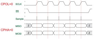
SPI interface: pins 10 (SS), 11 (MOSI), 13 (SCK). Hardware serial interface SPI pins.
I2C interface: pins 4 (SDA) and 5 (SCL). I2C hardware interface signals.
LED: pin 13. A general purpose LED is connected to this pin. Lights up when the signal level at pin 13 is high.
Analogue inputs: A0…A8. 6 or 8 analog inputs for voltage measurement. The ADC capacity is 10 bits, which corresponds to 1024 signal gradations. The measurement time is about 100 μs. To maintain accuracy, the output impedance of the signal source should not exceed 10 kOhms.
RST. Microcontroller reset signal. A low level causes the system to reboot. The RST pin on the 6-pin connector has a slightly different purpose and is used when loading a program into the microcontroller.
There are 2 LEDs on the board.
- Red LED indicating the presence of power to the microcontroller.
- Green LED. It is controlled by the program and can be used for any purpose chosen by the developer.
Schematic diagram of the Arduino Pro Mini board.
I have already talked about the board’s power supply circuits, but there is nothing more to explain. The microcontroller is connected according to the standard circuit; almost all of its pins are directly connected to the board pins.
Uploading the program to the Arduino Pro Mini board.
On Arduino boards with a built-in interface converter, this operation is very simple. The board is connected with a standard cable to the USB port of the computer, the button in the Arduino IDE is pressed and the program is automatically loaded into the board.
With the Arduino Pro Mini board everything is more complicated. There is nowhere to connect a standard USB cable.
How programs are loaded into Arduino boards from the Arduino IDE.
When you click the “Upload” button in the Arduino IDE, the sketch is compiled. What is indicated by the “Compiling sketch” inscription at the bottom of the window.
Then the “Loading” message automatically appears.
At this point, the Arduino IDE triggers a low level pulse on the DTR output. DTR is one of the COM port data transmission control signals. Usually it is formed at the output of the built-in USB-UART interface converter.
In all Arduino boards, the DTR signal is connected to the reset pin of the microcontroller through a 0.1 µF capacitor. The result is the simplest differentiating chain with a time constant of 1 ms.
The Arduino Pro Mini board does not have an internal interface converter, so the DTR signal is output to a 6-pin connector. The reset circuit from the DTR signal for Arduino Pro Mini looks like this.
Regardless of the duration of the DTR pulse, a short reset pulse will be generated at the “RESET” input of the microcontroller.
Upon any reset, the microcontroller transfers control to the bootloader program. For approximately 1 second, the bootloader waits for communication with the computer via the STK500 protocol. If data is received from the computer, then the program is loaded from the Arduino IDE.
If no data is received from the computer within a second, then control is transferred to the user program of the microcontroller. This happens, for example, when the power is turned on. The board waits for a second to see if data is about to be loaded into it, and then the already loaded program is executed.
From all of the above, it becomes clear that if the Arduino Pro Mini board is connected through a full-fledged interface converter with RXD, TXD and DTR signals, then loading will occur in exactly the same way as in other Arduino boards with a built-in interface converter. Additionally, you can use the 5 V signal from the USB interface to power the board. Or 3.3V for boards with 3.3V power supply.
The 6-pin connector of the Arduino Pro Mini board is used to connect an external interface converter (it can be soldered in if necessary). The connector contains all the signals necessary to load the program onto the board.
You just need to take into account that on some boards the RXI and TXO signals of the 6-pin connector may correspond to the RXD and TXD signals of the microcontroller, or they may be turned on the other way around. For example, like on this board.
It is better to ring the RXI and TXO pin circuits. On my board the signals match. The connection diagram of the USB-UART converter to my board looks like this.
Please note that the DTR signal must be connected to the RST pin on the 6-pin connector. It is connected to the reset input of the microcontroller through a differentiating capacitor. There is another RST pin on the board. It is connected directly to the “RESET” input of the microcontroller.
Any module can be used as an external USB-UART converter, for example, PL2303 USB-UART BOARD or CH340 module. Don't forget to install the driver for the interface converter module on your computer.
The trouble is that most interface converter modules do not have a DTR signal at the output connector. You can, of course, solder wires to the DTR pin of the converter chip. Almost all interface converter chips have this signal. It's just not connected to the module connector.
Another way is to use the RESET button on the Arduino Pro Mini.
When loading a program, you must press it at the right time. At the moment when the “Loading” message appears in the Arduino IDE window, you must briefly press this button. This takes approximately 1 second. In principle, this is not difficult to do, but when your head is full of program development, such a simple operation is somewhat annoying.
In the next lesson I’m going to start a new big topic - data exchange between Arduino boards.
Previous lesson List of lessons Next lesson
Support the project
0
Author of the publication
offline for 5 days
Edward
236
Comments: 1789Publications: 183Registration: 13-12-2015
Pro Mini circuit and pinout
The circuit diagram of the board looks like this:
Schematic diagram of the board
Now let's move on to the board pinout:
Microcontroller pinout
Programming
All programs are programmed using the free development environment for Arduino pro mini. The Arduino mini includes an ATmega328, into which the bootloader is pre-sewn. Therefore, the user can freely load programs into the microcontroller's memory.
Communication is provided by the STK500 protocol.
ATmega328 pinout
How to flash an Arduino Pro mini without a bootloader using an external programmer? Simply and easily.
First, you will need to cancel the requirement to press the reboot button before flashing the code of the written program.
Arduino mini pro is designed so that rebooting via software is available directly from any computer device. The 6 pins have one that is directly connected to the Arduino 328 pro reset line using a 100nF capacitor.
Through the control of the above pin, it is possible to convert USB or serial port by connecting to the connector. If you allow a level below normal to appear for an extended period of time, the platform will automatically reboot.
The Arduino IDE allows the user to upload code with the click of a button to download a free development environment.
Arduino IDE
However, the risk of unjustified consequences and platform failure increases. If the electronics engineer's computer has a Mac OS or Linux operating system installed, then a reset on the microcontroller will occur every time the software is connected to the platform using a USB cable.
Half a second after the reset, the bootloader starts working. Basically, the bootloader is designed so as not to intercept other data, but often the opposite happens: the first bytes of program data are intercepted and sent to the board when a connection is established.
To eliminate such a “bug”, it is necessary to check in the code of the program that will run on Arduino how the process of transferring program data from the computer to the platform is carried out. The optimal time to send the code is a second from the moment the connection between devices is established.
Programming on Arduino pro mini
The standard Arduino development environment is used >
In the Serial Port item, select the desired port to which the board is connected. Then you can upload the program to the board by clicking the Upload button.
The download may take a long time and eventually produce an error. To avoid this, when uploading a sketch, you need to press the reset button when the message Binary sketch size: xxx bytes appears. The LED indicators on the board will light up during booting. After uploading the sketch, you need to disconnect the microcontroller and apply voltage to it.
Project ideas
Today you can find any Arduino project on the Internet. And this is not surprising, because this platform is popular among novice developers of electronic devices for home and garden.
Below are several well-known and simple projects based on the Arduino platform:
- Alarm system built by connecting dfplayer to Arduino pro.
- Controllable design for quadcopter.
- Aquarium automation.
- Timer.
- Soil moisture analyzer.
- Automatic watering for indoor plants.
- A sensor that measures precipitation and wind speed.
Connecting the board
To connect the electronic platform to a personal computer, a CH340G cable with a built-in USB-USART interface converter is required. This gadget is connected using RX and TX pins. The cable is connected to the GND and VCC pins.
It is recommended to use amplifiers with a DTR connector, which automatically reboots the board after updating the microcontroller software code.
External power supply
Arduino Pro Mini is powered by a PC or other regulated source. Energy is transmitted through the CH340G cable or from the converter board. The following outputs are used to power the electronic platform:
- RAW, used to connect regulated voltage;
- GND, used for ground pin;
- VCC required to connect a power supply up to 5V.
When connecting boards with low power consumption, it is recommended to use a stabilizer. It limits current consumption to 150 mA depending on the power supply.
When purchasing a stabilizer, it is important to consider its dissipation power. At high parameter values, a short circuit may occur, which will lead to damage to the controller.
