Color marking of conductor insulation is important for faster and correct installation of electrical distribution devices, ease of repair and elimination of errors. The colors of wires in electrics are regulated by regulatory documents ( PUE and GOST R 50462-2009 ).
Installation and maintenance work in electrical installations is associated not only with ensuring reliability, but also safety. Complete error elimination is required. For these purposes, a system of color designations for core insulation has been developed, which determines what color the wires are phase, neutral and ground.
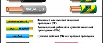
According to the PUE, the following colors of current-carrying conductors are allowed:
The above list contains many options for wire colors, but there are not several colors that are used only to indicate neutral and protective wires:
- blue color and its shades - working neutral wire (neutral - N);
- yellow with a green stripe - protective earth (PE);
- yellow-green insulation with blue marks at the ends of the conductors - combined (PEN) conductor.
It is allowed to use conductors with green insulation with a yellow stripe for grounding, and for combined conductors blue insulation with yellow-green marks at the ends.
The color must be the same in each circuit within one device. Branch circuits must be made with identically colored conductors. The use of insulation without differences in shades indicates a high standard of installation and greatly facilitates further maintenance and repair of equipment.
What kind of lighting do you prefer?
Built-in Chandelier
Expert opinion
It-Technology, Electrical power and electronics specialist
Ask questions to the “Specialist for modernization of energy generation systems”
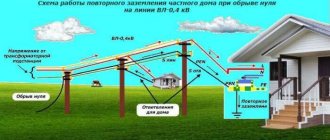
Zero break in three-phase and single-phase networks - consequences If one of the phases in a three-phase four-wire system breaks, the voltage in the two remaining phases will not change its value. Ask, I'm in touch!
Neutral wire in a three-phase network
To power electrical receivers of chemical fiber enterprises, in most cases, three-phase networks with a voltage of 380/220 V with a neutral wire and solid grounding of the neutral are used.
The cross-section of the neutral wire in electrical networks supplying production premises, starting from the transformer substation and in all internal networks, must be equal to the cross-section of the phase wires, regardless of the material. The selection of the cross-section of wires and cables for heating is made according to the tables of long-term permissible current loads. [31] Busbars are usually made of three or four wires with a neutral wire. The cross-section of the neutral wire can be equal to 25; 50 and 100% of the cross-section of the phase wire. Neutral wires with a cross section of 25 and 50% of the phase wire are typical for main busbars. [33]
It follows that in networks with a symmetrical load with gas-discharge light sources (as opposed to a symmetrical load with incandescent lamps), the choice of the cross-section of the neutral wire is determined mainly by higher harmonic currents. Therefore, the cross-section of the neutral wire is chosen equal to the cross-section of the phase wires. [34]
In practice, the current in the neutral wire is significantly less than the current in the phase wires. Therefore, in three-phase networks, the cross-section of the neutral wire is chosen two to three times smaller than the cross-section of the phase wire. [36]
In two-phase and three-phase lines with uneven phase loads, the cross-section of the neutral wire is calculated. In the event that the cross-section of the neutral wire is larger than the cross-section of the phase wire, it is allowed to use, if possible, one of the phase conductors as a neutral wire, and a neutral conductor as the least loaded phase, with protected cables and special wires. [37]
The possibilities for reducing the current / 0 are limited by the limits of the phase load equalization capabilities. The zero sequence resistance Z0 depends on the cross-section of the neutral wire. its length and the devices included in the neutral. But the determining factor on the value of Z0 is the zero-sequence resistance of the transformers supplying the network with a voltage of 380 - 660 V, which depends on the connection group of their windings. [38]
In single-phase and two-phase lines, the cross-section of the neutral or ground wire must be equal to the phase wire. In three-phase lines with phase-by-phase disconnection, the cross-section of the neutral wire is assumed to be equal to the cross-section of the largest phase wire. At the same time, in cable lines, if justified by calculation, it is allowed to use one of the phase conductors as a neutral wire, and a neutral conductor as a phase conductor with a minimum load. [39]
In the presence of repeated grounding, the single-phase fault current will be greater than without it, since with repeated grounding a parallel branch is formed in the circuit of the current through the person. In single-phase branches from mains (phase - zero), the cross-section of the neutral wire must be equal to the cross-section of the phase wires. There should be no switches or fuses on the neutral protective wire. [40]
Load asymmetry in industrial networks with a voltage of 380 V is sought to be limited by distributing single-phase loads across phases as evenly as possible. Thanks to this, the current / 0 is reduced and the cross-section of the neutral wire can be reduced by up to 50% compared to the phase wires. [42]
When calculating voltage losses in LV networks, as a rule, the reactive load and line reactance should not be neglected. It is allowed in the calculations to use the average reactance of the LV network: cable - 0 06 Ohm / km, overhead line 0 3 Ohm / km. The cross-section of the neutral wire in a four-wire three-phase current network is taken equal to half the cross-section of the phase wire, in one and two-phase branches - the cross-section of the phase wire. [44]
Let's sum it up
Of course, the probabilities of accidents are random; the most that can be done in such situations is to take the necessary measures to ensure protection. But besides this, it would not be superfluous to identify an emergency situation in time based on its characteristic signs. First of all, the burning out of the neutral main wire leads to network overvoltage. Having discovered the first signs of this phenomenon, you should turn off all electrical appliances.
Doing this quickly and independently is almost impossible. The time period for this is too short, so you should install special devices on the electrical panel that respond to a zero break. As soon as the voltage goes beyond the set limits, the voltage control relay will perform a protective shutdown.
You should not completely trust the security system. It may happen that if there are characteristic signs of voltage surges, a power outage will not occur. Therefore, it makes sense to list the most likely manifestations for this phenomenon:
- Flickering of incandescent lamps . They are most sensitive to the difference in voltage level that occurs when the zero is broken. Energy-efficient lighting fixtures and LED lamps are not as responsive to changes.
- Electronic devices with built-in protection are usually disconnected from the power supply. Or they don't start. Such actions are provided for by the protection response of pulsed power supply units to voltage surges. It is typical that such a reaction can operate earlier than the voltage relay. But this largely depends on the manufacturer and the implementation scheme for protecting electrical networks, as well as the reliability of the electrical connection.
- Another characteristic sign is an increase in the temperature of the switch . Even if you did not pay attention to the flickering of the lamps, this manifestation should cause concern.
- Sparking when trying to connect an electrical appliance may indicate a zero break at the input of a single-phase consumer. Even if it is caused by another factor, and not a zero break, this is a very bad sign.
- Spontaneous operation of input circuit breakers may also indicate overvoltage. This reaction to a zero break is typical when turning on electric heating devices, such as an electric furnace, boiler, kettle, etc.
- Characteristic sounds in the input electrical panel may also indicate voltage drops. In such a situation, it is recommended to turn off the power input and wait for the emergency team to arrive. There is a high probability that a zero-loss accident occurred in the supplier’s power grid.
- a voltage relay at the electrical network input . Ideally, it is advisable to duplicate this system with a voltage stabilizer for a house or apartment. Such a device, working in tandem with a relay, will allow you to maintain a given voltage level without turning off the power.
In fact, only multi-level protection can provide maximum security.
The principle of operation of the neutral conductor
If we consider new buildings and old-type apartment buildings, then the transmission of electricity and its principles will differ significantly. Networks of new houses are developed according to the TN-S type:
- the electric current passes from a transformer or generator with a secondary winding, which is connected as a star, when all the wires converge at one zero point;
- the other ends of the wires are allocated to three terminals, which are also connected to the zero point and connected along the ground loop to the substation;
- a wire with a high-voltage characteristic, if it has zero resistance, is divided into working N (blue) and protective PE (yellow-green).
Why is zeroing necessary?
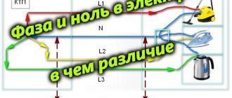
Humanity actively uses electricity; phase and zero are the most important concepts that need to be known and distinguished. As we have already found out, in phase electricity is supplied to the consumer, zero removes the current in the opposite direction. It is necessary to distinguish between neutral working (N) and neutral protective (PE) conductors. The first is necessary to equalize the phase voltage, the second is used for protective grounding.
Depending on the type of power line, an insulated, solidly grounded or effectively grounded zero can be used. Most power lines supplying the residential sector have a solidly grounded neutral. With a symmetrical load on the phase conductors, the working zero has no voltage. If the load is uneven, the unbalance current flows at zero, and the power supply circuit is able to self-regulate its phases.
Electrical networks with an isolated neutral do not have a neutral working conductor. They use a neutral ground wire. In TN electrical systems, the working and protective neutral conductors are combined throughout the entire circuit and are marked PEN. Combining the working and protective zero is possible only up to the switchgear. From it to the end consumer there are already two zeros - PE and N. The combination of neutral conductors is prohibited for safety reasons, since in the event of a short circuit the phase will be closed to neutral, and all electrical appliances will be under phase voltage.
Safety precautions during inspection
When working with electrical wires, you must follow the safety rules:
- Check voltage using instruments, and do not rely only on color markings. There are situations when electricians, through inattention or ignorance, installed electrical wiring without observing generally accepted connection conditions based on the colors of the wires.
- Before starting work, visually check the serviceability and integrity of the cable.
- Do not allow wires to come into contact with wet, hot, oily objects or surfaces.
- In factory-made complete switchgears, check the presence or absence of voltage using built-in stationary voltage indicators.
- Testing in electrical installations with a voltage of 35 kW is carried out using an insulating rod by contacting it with live parts. The presence of crackling and sparking indicates the presence of tension.
- Do not touch exposed electrical wiring.
- It is allowed to work with wiring from a stepladder if the height of the cables does not exceed 3 m from the floor. It is prohibited to place ladders on various supports (boxes, barrels, etc.).
What do the colors of electrical wires look like?
According to the rules, the insulating layer of the grounding cable must be painted green-yellow. The pattern may appear as yellow and green stripes applied along or across the cable by the manufacturer during manufacture. Sometimes the wire may only be yellow or only green. Such a core is designated in the diagram as “PE”. Grounding is often called neutral protection, but it is not a working zero, and they should not be confused.
You can designate a permanent chain with these colors:
In permanent networks there is no phase division; wires (buses) are positive and negative. There is also no zero here. According to the documents, the plus should be colored red, and the minus – blue. The conductor located in the middle is usually indicated by light blue or light blue tones.
Important! Sometimes it is necessary to determine which is positive if the wires are brown and blue. Everything is simple here. Zero, that is, minus, is almost always indicated by blue tones, and phase (plus) by brown, red and others.
You might be interested in Description and characteristics of wire SIP-4 4x16
Marking the connection in a three-phase home socket
Coloring phase
In cases where the electrical installation is installed using rigid metal busbars, the tires are painted with indelible paint in the following colors:
The color of the phases must be maintained throughout the entire device, but not necessarily over the entire surface of the bus. It is allowed to mark the phase designation only at the connection points. On a painted surface, you can duplicate the color with the “ ZhZK ” symbols for paint of the corresponding colors.
If tires are not accessible for inspection or work when there is voltage on them, then they may not be painted.
The color of phase wires connected to rigid busbars may not coincide with them in color, since there is a difference in the accepted designation systems for flexible conductors and rigid stationary distribution busbars.
Classification of power line neutrals
The purpose of power lines is very diverse. There is also a variety of equipment to protect them from leaks and short circuits. In this regard, neutrals are classified into three types:
- solidly grounded;
- isolated;
- effectively grounded.
If the power line with voltage from 0.38 kV to 35 kV is short and the number of connected consumers is large, then a solidly grounded neutral is used. Consumers of a three-phase load receive power thanks to three phases and zero, and consumers of a single-phase load receive power from one of the phases and zero.
With an average length of power lines with voltages from 2 kV to 35 kV and a small number of consumers connected to this line, insulated neutrals are used. They are widely used for connecting transformer substations in populated areas, as well as powerful electrical equipment in industry.
In networks with a voltage of 110 kV and higher, with a large length of power lines, an effectively grounded neutral is used.
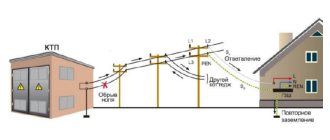
Three-phase network: why zero burnout occurs
For the most part, household consumers are powered using a single-phase circuit. But part of the power supply is still carried out using three-phase cables. Of course, high-quality cable products are characterized by strict technical and conductive parameters, which means they need to be laid and operated according to the rules, taking into account permissible load parameters.
What does the electrician’s phrase “Zero burnt out!” mean? Why does zero burn out much more often in a three-phase network than in a single-phase one? What are the forecasts? These and other questions arise for owners of houses and other objects with similar power supply. Let's figure out together how to prevent the development of such situations, thereby reducing the consequences and problems.
The concept of “zero” in a single-phase circuit
“Zero” for a single-phase circuit is one of two conductors that does not have a high potential relative to ground. The second conductor is the “phase”, which has a high potential (220 V for household networks). The electric current that flows through the phase is always equal to the current that flows through “zero”. That is why there are no prerequisites for zero burnout in a single-phase network. In addition, the line, as a rule, is protected by high-quality and inexpensive automation.
This is what it looks like schematically:
The concept of “zero” in a three-phase circuit
As many people know, three-phase lines are of two types regarding the load to the phases. Thus, the following types are distinguished: “star” and “triangle”. In the case of a delta connection, the zero is absent purely physically, which means there is simply no problem with the zero burning out. But the “star” circuit in a three-phase connection has a zero, like a special conductor. Let's take a closer look.
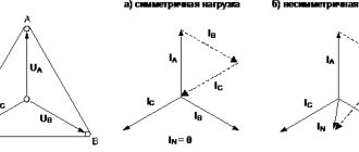
Star connection diagram in a three-phase circuit:
In this case, an equal load of alternating electric current passes through each of the 3 phases. At the same time, they shift in time phase by 120 degrees or by 1/3 of the entire period. The result is a sum of equal but shifted vector values that give a total value of zero. In fact, this is the ideal case when such zero current flows through the neutral wire. But in fact, a de-energized zero is not needed at all. The real situation is different from the ideal. After all, the loads of all phases in most cases are at least slightly different. That is, the total vector is not equal to zero. As a result, current compensation does not occur, which means that a small equalizing current passes through the neutral conductor. That is why in many cables with 3 phases there is a 4th core - zero, which is characterized by a smaller cross-section than the cross-section of the phase conductors. The main reason is saving electrical copper or aluminum. Upon closer examination, it becomes clear that such currents are not enough to cause zero burnout. What then is the reason?
The reason is that a three-phase line includes unbalanced single-phase loads. And at the same time, the difference in the magnitude of the loads can be very significant, which electricians characterize as “phase imbalance”. At the project stage, work is carried out to maximize the load equation on the phases, but in reality, power distribution is not always effective. When switching on high-power household appliances in one phase, there is no way to predict or compensate for the load on the remaining phases. As a result, a load difference is present. Paying attention to our own everyday life, have many of us wondered how much the load will affect the cable lines when the washing machine and electric kettle are turned on at the same time? It is difficult to think about equalizing currents and the neutral core when you know nothing about it.
Even in such cases, when the total value of phase currents is not zero, extreme situations do not develop. Zero can burn out very rarely.
Zero burnout – when does it happen?
When does this notorious burnout occur? And is it worth talking about it? And here there is one small “but”. Since the 90s, the concept of a switching power supply, which is used to save electricity, has firmly entered into our everyday life. It is used everywhere - computers, various household appliances. Moreover, in such power supplies the current flows only in one third of a full half-cycle. As a result, uncompensated currents begin to flow in three-phase networks, which flow without any control into the neutral wire. At “zero” there are currents of different phases from an asymmetric load. When summing up this data, it turns out that the zero current can correspond to a value close to or exceeding the rated phase value. But this is precisely fraught with the same burnout of zero.