In an autotransformer, part of the turns of the primary winding is used as a secondary winding. It is advisable to use autotransformers when the voltage needs to be reduced only a little, not by several times, as conventional transformers do, but for example by 0.7 times.
Various electrical equipment and modern electrical networks in general primarily use alternating current for their operation. Alternating current powers engines, induction furnaces, machine tools, computers, heaters, heating elements, lighting fixtures, and household appliances. It is impossible to overestimate the importance of alternating current for the modern world. However, high voltage is used to transmit electrical energy over long distances. And the equipment requires a reduced voltage for its power supply - 110, 220 or 380 volts. Therefore, after transmission over a distance, the electrical voltage must be lowered. The reduction is carried out in steps using transformers and autotransformers.
In general, transformers are step-up and step-down. Step-up transformers are installed in power generating plants, where they increase the alternating voltage received from the generator to hundreds of thousands and even millions of volts, suitable for transmission over long distances with minimal energy loss. And then this high voltage is lowered again using transformers.
A conventional power or network transformer is an electromagnetic unit, the purpose of which is to change the effective value of the alternating voltage supplied to its primary winding. A transformer in its canonical form has several windings, but at least two - primary and secondary. The turns of all windings of the transformer wrap around a common magnetic circuit - the core. The primary winding is supplied with a voltage whose value must be changed; a consumer or a network with sockets from which numerous consumers will be powered is connected to the secondary winding(s). The operation of the transformer is based on Faraday’s law of electromagnetic induction. When alternating current flows through the turns of the primary winding, an alternating electromagnetic field of this current acts in the space inside (mostly) the winding. This alternating magnetic field is capable of inducing an induced emf in the secondary winding, which covers the space of action of the magnetic flux of the primary winding. In a conventional transformer, the primary windings are galvanically isolated from the primary windings. In an autotransformer, part of the turns of the primary winding is used as a secondary winding. It is advisable to use autotransformers when the voltage needs to be reduced only slightly, not by several times, as conventional transformers do, but for example by 0.7 times.
Thus, the main difference between a transformer and an autotransformer is that in a conventional transformer the windings are electrically isolated from each other, while the windings of an autotransformer have common turns and are therefore always galvanically connected. In a transformer, each winding has at least two of its own terminals; in an autotransformer, one terminal will always be common to the primary and secondary windings.
Autotransformers are widely used in networks with voltages of more than 100 kV, since during a stepwise reduction in voltage, when it is clear that the windings of the final transformer will be galvanically isolated, the absence of galvanic isolation at the autotransformer stage is not critical. But from an economic point of view, autotransformers are much more profitable than conventional ones. They have less losses in the windings due to the smaller amount of copper in the wires than conventional transformers of similar power. The size of an autotransformer for the same power is smaller - lower costs for materials and core. Autotransformers have a higher efficiency, because only part of the magnetic flux undergoes transformation. And in general, the cost of an autotransformer is lower. The disadvantages of an autotransformer, unlike a conventional one, include the lack of galvanic isolation between the primary and secondary circuits. If the insulation is damaged for any reason, the low voltage winding will be exposed to high voltage. Therefore, autotransformers are usually not used in everyday life so as not to expose the average person to the danger of electric shock.
At voltages up to 1000 volts, autotransformers are used to regulate voltage in the form of laboratory devices - laboratory autotransformers (LATRs) and as part of electromechanical voltage stabilizers (see - Network voltage stabilizers 220V - comparison of different types, advantages and disadvantages)
A transformer usually consists of several windings (two or more) wound on a common steel core. One winding is connected to the AC source, and the other winding(s) is connected to the electrical current consumer. The operation of the device is based on the use of electromagnetic induction (Faraday's law). In other words, a change in the magnetic flux passing through the winding creates an electromotive force in this winding. In transformers operating at ultra-high frequencies, sometimes there may be no magnetic core; such devices are called air-type. In cases where it is necessary to change the voltage within small limits, an autotransformer is used.
Electrical equipment for different purposes requires different voltages to operate. For example, household equipment is designed for 220 or 110 V. Industrial equipment is usually 380 V. And since high voltage is required when transmitting electric current over long distances (to reduce the overall losses of electricity during transportation), it is used in series to power local networks decrease by steps. All these voltage transformations are carried out using transformers or their varieties - autotransformers. Transformers, depending on the needs, are step-up (increase the voltage) and step-down (lower the voltage). In both cases, the essence of the operation of this device is the same - to achieve the required voltage of electric current.
- Definition
- Difference
- Conclusions TheDifference.ru
Difference
So, the main difference between a transformer and an autotransformer is the number of windings. Transformers have two or more of them, autotransformers have one. Autotransformers are widely used in networks with voltages of 150 kV and higher, due to their lower cost than transformers and lower losses in active power windings (compared to transformers of the same power). In addition, autotransformers are much smaller in size than transformers. The main advantage of autotransformers over other types of transformers is their higher efficiency, since only part of the power is converted into them. In addition, due to lower consumption of steel for the core, copper for windings, smaller dimensions and weight, the cost of this type of transformer is significantly lower than that of other options. The disadvantage of autotransformers (in comparison with transformers) is the lack of electrical insulation between the primary and secondary windings. This is not important for industrial networks, where in any case the neutral wire must be grounded, but it is unacceptable for use in everyday life, because in case of accidents in autotransformers, the higher voltage from the primary winding may well be applied to the lower one (insulation breakdown of conductive parts). As a result, all parts of the installation will be connected to the high-voltage part, which is unacceptable according to safety rules when servicing such equipment. For domestic needs, a more reliable and safe transformer is usually used.
But violations can also occur with them, which will result in breakdown. To prevent this from happening, special protection is provided in the autotransformer. Its essence is that in case of any overload, the device gives an appropriate warning signal, and if the device fails, an automatic shutdown is triggered. Autotransformer protection is divided into several types:
Transformers are a fairly diverse group of equipment, with significant internal differences in purpose and design features. In addition, different equipment requires different voltages to operate. There are averages. Which are taken into account when drawing up a technical permit for connection. For example, household appliances are designed for 220 or even 110 V. But industrial-type equipment uses 380 V. They have their own options, lighter and less expensive. But before you decide to use it, you should know the difference between a transformer and an autotransformer.
Why is the voltage reduced?
Transmitting electricity over long distances requires high voltages, otherwise losses during energy transportation will make the process unprofitable. But in order to use electricity for industrial and, especially, domestic purposes, its reduction is required. This is done gradually, thanks to a system of transformers, as well as their more mobile analogues - autotransformers.
Despite the fact that all devices of this type are designed to convert the original voltage to the desired one, transformers can be divided into two types. The first - step-up - increase the voltage, maintaining it at a sufficient level for continued transportation or for industrial use. The second - step-down - on the contrary, reduce the voltage, allowing the energy to be used for domestic purposes.
What are both devices? ↑
Any transformer is a static type device that converts alternating current, frequency, and the number of phases. This device includes two or more windings that are wound on a single steel core. One of the windings must be connected to an alternating current source. The rest can be connected to end consumers. As a result, both electromagnetic and electrical connections are observed between them. Additionally, the winding of the autotransformer is equipped with three or more terminals, that is, it is possible to connect to different terminals and, accordingly, obtain different voltage values. The principle of operation is based on the well-known electromagnetic induction. Simply put, the magnetic flux that changes as it passes through the winding forms an electromotive force in it. This type of transformer is perfect for changing voltage in a relatively small range.
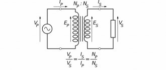
The ratio of the EMF values is expressed by the formula: E1/E2 = w1/w2 = k, where E is the EMF, w is the number of turns, k is the transformation ratio.
The operation of electrical equipment is ensured by a system of step-up and step-down transformers. The devices “differ” in a number of characteristics. Household units are designed for voltage of 110 or 220V, and household units are designed for 380V. Some of the presented devices reduce or increase voltage, others transfer electricity gradually from the substation to consumers.
Similar actions are performed by “transformers and autotransformers”. The units are characterized by some differences. However, such devices are designed to maintain the required voltage level in the network. To learn how to use such equipment correctly and safely, you need to consider their main differences.
- 1 Basic definition
- 2 Main differences
Design
The transformer design assumes the presence of one or more individual coils (tape or wire), located under a single magnetic flux, wound on a core made of a ferromagnet.
The most important structural parts are as follows:
- winding;
- frame;
- magnetic circuit (core);
- cooling system;
- insulation system;
- additional parts necessary for protective purposes, for installation, to provide access to the output parts.
In devices you can most often see two types of winding: the primary, which receives electric current from an external power source, and the secondary, from which the voltage is removed.
The core provides improved return contact of the windings and has reduced magnetic flux resistance.
Some types of devices operating at ultrahigh and high frequencies are produced without a core.
The production of devices is established in three basic winding concepts:
- armored;
- toroidal;
- core.
The design of core transformers involves winding the winding onto the core strictly horizontally. In armor-type devices it is enclosed in a magnetic circuit and placed horizontally or vertically.
Reliability, operational features, design and principle of operation of the transformer are taken without any influence from the principle of its manufacture.
What is the difference between a transformer and an autotransformer?
To convert voltage in electrical engineering, transformers or autotransformers are used. Due to the similarity of the names of these two devices, they are often confused or equated to the same thing. However, this is not the case, although the principle of operation is similar, the design and their scope of application are fundamentally different. Therefore, let's look at the differences between a transformer and an autotransformer to understand what is the difference anyway?
Definitions
A transformer is an electromagnetic device that transmits energy through a magnetic field. It consists of two or more windings (sometimes called coils) on a steel, iron or ferrite core, depending on the number of phases, input and output voltages. Its main feature is that the primary the circuit and the secondary are not electrically connected to each other, that is, the windings do not have electrical contacts. This is called galvanic isolation. And such a connection of coils is called inductive. Below you see a conventional graphic designation of a two- and three-winding transformer on an electrical circuit diagram:
They come in step-up, step-down and isolation modes (input voltage equals output voltage). Moreover, if you apply power to the secondary winding of a step-down transformer, you will receive an increased voltage on the primary windings, and the same rule works for a step-up transformer. An autotransformer is one of the transformer options with one winding wound on a core, in principle similar to the previous case. In it, unlike ordinary trance, the primary and secondary circuits are electrically connected to each other. This means that it does not provide galvanic isolation. You can see the conventional graphic designation of the autotransformer below:
Autotransformers come with a fixed output voltage and adjustable. The latter are known to many as LATR (laboratory autotransformer). They can also be either downward or upward. In an adjustable LATR, the secondary circuit is connected to a contact sliding along the coil.
Important! Due to the lack of galvanic isolation, autotransformers, by definition, cannot be isolating, unlike conventional ones! Another difference is the number of autotransformer windings - usually it is equal to the number of phases. Accordingly, to power single-phase devices, single-winding products are used, and for three-phase devices, three-winding products are used.
Operating principle
Briefly and in simple words, let's look at how each design option works. A transformer has at least two windings - primary and secondary (or several). If the primary is connected to the network (or another source of alternating current), then the current in the primary winding creates a magnetic flux through the core, which, penetrating the turns of the secondary, induces an emf in them. The principle of operation is based on the phenomena of electromagnetic induction, in particular Faraday’s law. When current flows in the secondary winding (to the load), the current in the primary winding also changes due to mutual induction. The voltage difference between the primary and secondary windings is determined by the ratio of their turns (transformation ratio). Up/Ud=n1/n2 n1, n2 – the number of turns on the primary and secondary. Speaking about an autotransformer, it has one winding, if there are several phases, there are the same number of windings. When alternating current flows through it, the magnetic flux that arises inside it induces an emf in the same winding.
Its value is directly proportional to the number of turns. The load (secondary circuit) is connected to the tap from the turns. On a step-up autotransformer, power is supplied not to the ends of the winding, but to one of the ends and a tap from the turns, unlike a transformer.
What was shown in the diagram above.
Main differences
To make it easier for you to understand the difference between a regular transformer and an autotransformer, we have compiled their main differences in a table:
| Transformer | Autotransformer | |
| Efficiency | The efficiency of an autotransformer is greater than that of a conventional one, especially when the difference between the input and output voltage is insignificant. | |
| Number of windings | Minimum 2 or more depending on the number of phases | 1 or more, equal to the number of phases |
| Galvanic isolation | Eat | No |
| Electric shock hazard when powering household electrical appliances | With an output voltage of less than 36 Volts - small | High |
| Safety for powered devices | High | Low, if there is a break in the coil on the turns after the output to the load, the entire supply voltage will fall on it |
| Price | High, the consumption of copper and steel for cores is high, especially for three-phase transformers | Low, due to the fact that there is only 1 winding for each phase, the consumption of copper and steel is lower |
Transformers are used everywhere - from power plants and substations designed for tens and hundreds of thousands of volts, to powering small household appliances. Although power supplies have been used recently, they are also based on a generator and a transformer with a ferrite core.
Autotransformers are used in household network voltage stabilizers. LATRs are often used in laboratories when testing or repairing electronic devices. Nevertheless, they have found their application in high-voltage networks, as well as for the electrification of railways.
For example, railways use such products in 2x25 networks (two 25 kilovolts each). As in the diagram above, a 50 kV line is laid in sparsely populated areas, and 25 kV is supplied to the electric train via a contact wire from a step-down autotransformer. This reduces the number of traction substations and line losses. Now you know the fundamental difference between a transformer and an autotransformer. To reinforce the material, we recommend watching a useful video on the topic: You probably don’t know:
The structure of the technical device in question has already been discussed above. But the question arises: what magnetic materials are used to ensure its uninterrupted operation?
In the simplest case, there are two windings connected in series on a closed magnetic circuit. Depending on the connection option of the energy source and load, the autotransformer can operate as a step-up or step-down.
There is a design that implements a mechanism for manual regulation of the output voltage (Variac, LATR). Automatic control units with feedback are also used; in fact, an autotransformer with such a device can be called a voltage stabilizer.
Scope and types
transformer in tv
Household transformers protect equipment during voltage surges.
Therefore, they are used in the following devices:
- in lighting;
- oscilloscopes;
- TVs;
- radios;
- measuring devices, etc.;
Welding units that separate the power and welding networks are actively used in welding and electrothermal structures, where they successfully reduce the voltage to the required ratings.
The power grid uses oil-fired units with voltages of 6 and 10 kV.
Many automatic designs use transformers, where the voltage on the coils is non-suctional.
Kinds:
- Rotating. The signal is transmitted to objects that rotate. For example, a video recorder, where the signal is transmitted to the drum of the magnetic head assembly. Here there are 2 halves of the magnetic circuit and their rotation occurs with a minimum gap in relation to each other. Based on this, a high speed of revolutions is realized; in the contact signal method it is not considered possible to achieve such an effect.
- Peak transformer. In this option, the sinusoidal voltage is converted into spikes that have a peak shape. They are actively used in the control of thyristors, as well as electronic and semiconductor devices.
- Coordinator. Takes part in matching resistances in different intervals of the electronic circuit, while the signal shape is minimally distorted. Galvanic isolation between circuit zones is synchronously ensured.
- Dividing. Here the 2 windings are not electrically connected to each other. This scheme makes it possible to increase the safety of electrical networks. When an accidental simultaneous touch of a live part and the ground occurs, galvanic isolation of the electrical circuit is generated.
- Pulse. In this option, pulse signals are converted in a very short period of time (tens of microseconds), while the curvature of the pulse configuration is minimal.
- By voltage. Here the conversion of high voltage to low voltage occurs. This option allows you to isolate measurement and logic circuits from high voltage.
- By current. This type measures high current circuits. For example, in the designs of relay panels of electrical power systems. Therefore, fairly stringent accuracy requirements apply.
- Autotransformer. In this type, the two windings are connected directly. As a result, an electrical and electromagnetic connection is created, which explains the high efficiency of this type. The disadvantage of such a device is the lack of insulation, that is, there is no galvanic isolation.
- Power. This option is used with variable current and converts electrical energy in installations and power networks. This type is widely used on high-tension power lines (35-750 kV), city electrical networks (10 and 6 kV).
- Twin throttle. The presence of 2 equal wraps makes it possible to obtain a more effective throttle than a conventional one. They are used at the filter input in the power supply, as well as in audio equipment.
- Transfluxor. The remaining magnetization of the magnetic wire is large, which makes it possible to use it for storing information.
Operating principle of an autotransformer
In an autotransformer, energy is transferred not only by magnetic flux, but also electrically, since the windings have a galvanic connection. The closer the transformation ratio is to 1, the less energy is transferred electromagnetically. Below you see a diagram of a step-down autotransformer, an alternating voltage source is connected to the primary winding, and a load in the form of an incandescent lamp is connected to the terminals of the secondary winding.
In idle mode, the autotransformer works like a regular transformer. When a load is connected, the alternating magnetic flux arising in the core induces an EMF in the turns of the secondary winding directed towards the EMF of the energy source. Therefore, the current flowing through the secondary winding is equal to the difference between the load current and the primary circuit current. This allows the secondary winding to be made from small diameter wire. The savings on copper are smaller, the more the transformation coefficient differs from unity.
How to make it yourself
The step-down transformer can be made as a separate device or located in the power supply of the equipment. In fact, this is a radio-electronic element and you can make it with your own hands.
First, you should prepare the tools and material and make a preliminary calculation. To work you will need:
- high quality tape insulation;
- a core taken from an old TV;
- wires with enamel insulation;
- a simple winding machine, for example, from a board (width - 10 cm, length - 40 cm).
Step by step steps:
- Make a frame by cutting out an inner part from cardboard, slightly larger than the core rod. If an “O” shaped core is used, then 2 coils will be required. With a core shaped like “W”, one coil is enough.
- Pre-wind the round core with 3 layers of insulation after the primary winding.
- Wind the second layer with and bringing the ends of the winding out. The secondary and primary windings are laid in the same direction. The main thing is not to forget to remove the wires.
- Insert the iron strips into the finished coil, bend them around the frame on one side, and connect at the bottom. Leave an air gap between the frame and the core.
- Make a base for the transformer. Attach 2 bars (50x50 cm) to a board (5 cm thick) with metal staples at a distance of 30 cm from each other. Bend the staples so that they go around the bottom of the core.
- Bring the ends of the windings onto the frame and attach them to the contacts.
For every Volt there should be 10 turns. It is not difficult to calculate the required number. The core can be removed from any type of unnecessary transformer or made from tin. A tin can is suitable, from which 80 strips are cut out, 30 cm long and 2 cm wide. Their strips are annealed in a furnace, cooled, cleaned of scale and varnished. You can cover one side with thin paper.
The note! All markings and lines cannot be made with graphite.
The design is calculated using the formula P = U * I,. The power that can withstand the secondary winding is calculated from it.
Classification according to tactical and technical parameters
Since transformers find the widest application in radio-electronic devices operating in various conditions, it is accordingly necessary to select transformers suitable for the technical operating conditions.
1. Scope of application of transformers. This feature determines the scope of application and requirements for transformers in this area:
- for household purposes. They are characterized by insignificant requirements for operating conditions in domestic (home) conditions and are used in broadcasting equipment;
- general industrial use. Transformers of this type work, as a rule, in measuring equipment, control equipment of various machines, etc.;
- special purpose. Transformers of this type are used, as a rule, in military and special-purpose equipment. The requirements for them depend on the specific area of use, therefore special-purpose transformers are divided into the following categories according to their use in equipment: on-board equipment (aviation and missile), ship equipment (for surface and submarine ships), ground stationary equipment (various stations ), ground transportable (mobile ground equipment) and ground portable equipment (communication equipment).
2. Service life. This factor is related to the previous parameters, since the application area determines different requirements. The service life is understood as the total time of use of the transformer in the on state. The following categories can be distinguished:
- long service life, operating time is from 10,000 hours. Transformers for household appliances, general industrial use and some types of special purpose can be included;
- short service life, service life is 300 - 500 hours. This group includes transformers for aircraft equipment, and in some cases, ship and ground equipment;
— short-term use, the duration of operation without loss of characteristics is about several minutes. This category consists of missile equipment transformers.
3. Temperature conditions and operation of transformers also depend on the conditions of their use. These conditions determine the following quantities: ambient temperature, operating temperature of the windings and overheating of the windings. Thus, the following categories of transformers are distinguished according to temperature conditions:
- ordinary transformers with an operating temperature of no more than 100-130 ° C;
— high-temperature transformers with an operating temperature above 130 °C.
It should be noted that the ambient temperature of the transformer is determined by its area of application, and overheating and operating temperature are determined by the class of insulation used in the transformer.
Theory is good, but without practical application it’s just words. Here you can do everything with your own hands.
Flaws
Before putting the presented equipment into operation, it is necessary to study its main disadvantages:
- A low voltage type circuit will be significantly affected by high voltage levels. To avoid network failure, you will need to create a well-designed low voltage supply system. Only in this case will the device be able to withstand increased loads.
- The flux dissipated between the windings is negligible. If certain faults occur, a short circuit may occur. Its probability in this case increases significantly.
- The connections that are made between the secondary and primary windings must be identical. Otherwise, some problems may occur during the operation of the unit.
- It is impossible to create a system with grounding on one side. Both blocks must have a neutral.
- The presented system makes it difficult to maintain electromagnetic balance. To improve this indicator, you will need to increase the body of the device. If the transformation range is significant, resource savings will be negligible.
It should also be noted that when repairing an autotransformer, eliminating problems and emergencies that have arisen, the safety of the operating personnel may be reduced. Higher voltage can also be observed on the lower winding. In this case, all elements of the system will be connected to the high-voltage part. According to safety rules, this state of affairs is unacceptable. In this case, there is a possibility of breakdown of the insulation of conductors that are connected to electrical equipment.
Having examined the main features of the operation and design of autotransformers, we can draw conclusions about the advisability of using them for our own purposes.
Current transformers
To understand the difference between a current transformer and a voltage transformer, you need to know the features of the first and second devices. Current transformers are created primarily as measuring or protective devices.
Protection transformers
The basic function of these transformers is easy to understand. They strictly “monitor” that anyone who climbs into the electrical network does not receive a fatal blow. A distinctive feature is strict control. In the electrical system itself, a very high voltage is maintained for comfortable operation of the devices. However, any equipment can sooner or later fail, so it is imperative to leave a window through which repair specialists can check the condition of the network and carry out preventive work. This happens due to a current transformer, which in a certain place provides the most secure access.
Instrument transformers
Instrument transformers are special devices. Their main task is to convert alternating current, which results in the same alternating current, but with values acceptable for measurement. Using this device, you can connect a voltmeter, ammeter or any other measuring device to the circuit.
There is also an additional function - the ability to connect any equipment without spoiling it, and also to obtain the most accurate and correct measurement result (sometimes even tenths can radically change the picture).
Regardless of the specific type, the main feature of a current transformer is its extreme precision, as well as the ability to form some necessary safety insulation.