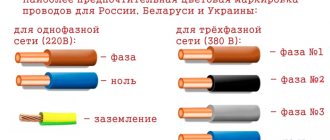
Not all manufacturers of USB devices adhere to the generally accepted color coding of wires: Red, White, Green, Black.
This article is dedicated to the rampant Chinese fantasy.
If your keyboard or mouse cord comes loose, read Repair Tips. If your device has non-standard wire color coding, there is a chance that here ▼ you will find the information you need.
On the boards of some mice/keyboards, the letter designations differ from the generally accepted ones: • instead of “D−” - D • instead of “D+” - C
Sometimes these designations are confused, which is generally not critical. Just swap the D- and D+ wires if the unit doesn't work.
Joystick Defender Game Racer Turbo:
If you have information about those devices that are not mentioned here, please unsubscribe in the comments to this article.
For custom PS/2 cord colors, see the PS/2 Mice and Keyboards article.
PS/2 connector
Joystick Defender Game Racer Turbo:. If you have information about those devices that are not mentioned here, please unsubscribe in the comments to this article. The pin assignments of the USB plug are clearly defined, see. I received a rather weak Defender laser mouse that was not working. When checking, I discovered that the wire was broken and decided to replace it. After rummaging around on the Internet, I discovered that almost all mice have different wire colors. Comment from Sergey [February 16, ]Please help.
I want to re-solder to a spare wire from the A4Tech keyboard. Where do you need to solder - Red-blue, Red-green, Copper-blue, Copper-green wires? If you spend most of your time at a computer and use your keyboard and mouse very actively, you've probably had to deal with their breakdowns. There's nothing you can do about it. Sooner or later, any equipment can fail. And it’s better if it’s a mouse and not some other, more complex and expensive component of your computer.
Prepare a new mouse. Now it will become your right hand and will help you find the necessary information, play games, watch videos, movies, work, etc. To do this, determine the type of interface that it uses. To connect the mouse to the computer, find the connector required for connection, located on the rear panel of the system unit. He's not alone there. There are two of them: green and purple. And if purple is for connecting a keyboard, remember, this information may be useful to you in the future, then green is just for a mouse.
In this case, the mouse will work from any connector. Unfortunately, not all motherboards have this feature. The possibility that the connector is completely missing should not be excluded. The presence of one connector requires connecting either a mouse or a keyboard.
To connect a second device, you definitely need a USB connector. If your new mouse has a USB interface, feel free to connect it to the correct connector. Today, most modern computers have a sufficient number of USB connectors designed to connect various devices. Some of them, for convenience, can be located on the front panel of the system unit case.
Connect the new mouse to the connector that is most convenient for you. A big help for you will be the fact that when you connect a new mouse, the standard driver will be automatically installed.
Therefore, you will not need any additional effort to set up this device. However, if the mouse has additional buttons and, accordingly, additional functions, you will have to install the drivers yourself. But here everything is quite simple. A CD will be included with this mouse. Turn on the computer and insert this disc into the computer drive. After completing the program associated with installing the mouse driver, it may be necessary to reboot the system.
A little theory
If you open the keyboard cable, you will find 4 wires
:
- power
cable (5 V) - ground wire
- sync
wire (
CLK) - data
wire (
DATA
)
Every key
on the keyboard has
its own 8-bit code
, called
a scan code
and is written in hexadecimal form (HEX), see below.
When you press a key
,
rectangular pulses
are transmitted SLK , and
11-bit code
DATA Data bits are read by the computer at the CLK
from
high
to
low level.
First bit
is always equal to
0
- this is
the start bit
, followed by
8
bits
of the scan code
, followed by
a parity bit
and at the end
a stop bit
, which is always equal to
1
.
How to solder a connector. USB2.0 and USB3.0 wiring by color (micro and mini connectors)
The pin assignments of the USB plug are clearly defined, see. A very useful site, where it is simple and accessible in normal Russian language, black and white, it is explained in detail what and where to solder. It simply couldn’t be simpler, before soldering, let’s turn on our brains, because that’s what they’re given to us for, take a piece of paper and draw a simple diagram. If the required pinout is not here, it doesn’t matter - for this there is the vast and powerful Internet, where you can find everything you need by the name of the company. The guys who share their knowledge have great respect and respect, well done!!
How does a computer mouse work?
A mouse, like any peripheral device, has a “brain” - a microcontroller (chip).
The microcontroller communicates with the computer via a wired or wireless interface.
The Wireless interface gives more freedom, but there must be a power source (1 - 2 AA or AAA elements with a voltage of 1.5 V) in the manipulator itself.
Data exchange with the computer is carried out through transceivers (transceivers), one of which is located in the manipulator itself.
The other looks like a small flash drive and connects to the USB port of the computer.
The wired interface can be USB or PS/2. The latter is gradually replaced by the former and is less common. The USB interface connector - unlike PS/2 - can be switched on the fly.
The manipulator contains an emitting diode (LED), an optical system and a detector of received radiation (photodetector), the signal from which is sent to the microcontroller.
The LED can emit visible (red) light or invisible (IR - infrared - radiation).
The signal emitted by the LED is reflected from the surface, passes through the optical system (prism) and enters the photodetector (sensor).
When the manipulator moves, the nature of the reflected signal changes, and the microcontroller of the manipulator, processing it, controls the cursor on the monitor screen.
The mouse has a scroll function, which makes working with documents more convenient.
The scrolling device includes a wheel with slots and an optocoupler - an LED and a photodetector (photodiode or phototransistor).
As the wheel rotates, the radiation flow from the LED to the photodetector is periodically interrupted.
The microcontroller, processing the resulting series of pulses, controls the scrolling of the document on the monitor screen.
Instead of an optocoupler, a variable resistor can be used in the scrolling device.
Rotation from the wheel shaft is transmitted to the moving contact of the resistor.
As the wheel rotates, the resistance of the variable resistor changes, and this is monitored by the microcontroller.
The scrolling device has a separate button, hidden in the bowels of the manipulator, which allows you to scroll the document automatically.
To automatically scroll, you need to rotate the wheel and press it.
The scroll button will operate and the scroll will enter automatic mode.
The appearance of the cursor on the monitor screen will change.
Any mouse has at least three buttons - left, right and for scrolling.
The left button is used more often than others. Gaming mice have more buttons.
Do-it-yourself mouse cable repair
USB cable pinout refers to the description of the internals of the Universal Serial Bus. This device is used to transfer data and charge batteries of any electronic devices: mobile phones, players, laptops, tablet computers, tape recorders and other gadgets. Carrying out high-quality pinouts requires knowledge and ability to read diagrams, orientation in the types and types of connections, you need to know the classification of wires, their colors and purpose. Long-term and uninterrupted operation of the cable is ensured by the correct wire connection of the 2 USB and mini-USB connectors. The Universal Serial Bus is available in 3 versions - USB 1.
USB Specifications
USB options have improved with increasing popularity among users. Along with the increase in the productivity of computer technology, the requirements for the quality of information transmission gradually increased. To meet growing needs, updated USB specifications from version 1.1 to 3.2 Gen2x2 were developed.
USB1.1
USB1.1 was widely used to equip computer devices until April 2000. Its basic properties delighted many users. Let's look at them in more detail, for one connected device (unless otherwise indicated):
- support for two information exchange rates: high (up to 12 Mbit/s) and low (up to 1.5 Mbit/s);
- cable length: 3 m (unshielded), 5 m (shielded);
- number of peripheral devices per connection - up to 127;
- supply voltage – up to +5 V;
- maximum current consumption – up to 500 mA;
- simultaneous use of two data rates on one bus is possible.
In low speed mode they usually connected: computer mice, keyboards, modems, joysticks, in high speed mode: automatic telephone exchanges, laser and inkjet printers, external hard drives, video cameras.
USB2.0
The most common currently, due to its simplicity and low cost, is high-speed 2.0. Compared to its predecessor, a new “High-Speed” parameter was added to this standard. With it, the data exchange speed increased to 480 Mbit/s, while other characteristics did not change. To highlight this feature, a special “Hi-Speed” logo was invented.
USB3.0
In 2008, developers presented the world with a new specification - USB3.0. Its speed mode has increased significantly and amounted to 5 Gbit/s (SuperSpeed). The maximum current consumption for devices has increased to 900 mA. To improve performance, 5 more contacts have been added to this standard, which are placed separately in the connector. Subsequently (since July 31, 2013) new USB3.1 were created: up to 5 Gbit/s (SuperSpeed); 3.2 up to 10 Gbit/s (SuperSpeed+).
Based on the USB3.0 architecture, optical cables went on sale in 2013, capable of transmitting data at speeds of up to 1 GB/s and a distance of up to 100 m. However, supplying power to end devices via them is impossible.
On September 22, 2022, USB3.2 was introduced to the market with a stated throughput (using dual-lane transmission via the Type-C connector) of up to 10 Gbps (SuperSpeed) and 20 Gbps (SuperSpeed+). It became the final version in the 3.x specification. The first commercial products using it will appear in Russia at the beginning of 2022.
USB4
USB3.2 is just starting to appear on sale. Despite this, as of 2022, data on the specification of the new USB4 interface can be found online. For it, the declared speed limit is 40 Gbit/s.
The manipulator is not working. What to do?
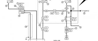
A logical diagram will help us diagnose and troubleshoot problems (clickable image). You can download the high-resolution diagram here. The logical circuit contains logical blocks in the form of a diamond with inputs and outputs “yes” and “no”, rectangular blocks indicating a specific action and arrows, following which the diagnostic and repair process is carried out.
Different block chains are marked with different colors. Blocks marked in black will help us diagnose interfaces and the manipulator controller, blue blocks will help us solve problems with buttons, and purple blocks will help us solve problems with scrolling.
At the beginning of the repair, you need to decide on the interface (blocks 1 and 2) on the logical diagram.