Creating a solar USB charger for your phone with your own hands is one of the most interesting and useful projects on VELOFAN. Making a homemade charger is not too difficult - the necessary components are not very expensive and are easy to obtain. Solar USB chargers are ideal for charging small devices such as a phone.
The weak point of all homemade solar chargers is the batteries. Most solar chargers are based on standard nickel-metal hydride batteries - cheap, accessible and safe to use. But unfortunately, NiMH batteries have too low voltage and capacity for them to be seriously considered as chargers for modern gadgets, the energy consumption of which is only growing every year.
For example, the iPhone 4's 2000 mAh battery can still be fully recharged from a homemade solar charger with two or four AA batteries, but the iPad 2 is equipped with a 6000 mAh battery, which is no longer so easy to recharge using a similar charger.
The solution to this problem is to replace nickel-metal hydride batteries with lithium ones.
From this instruction you will learn how to make a solar USB charger with a lithium battery with your own hands. Firstly, compared to commercial chargers, this homemade charger will cost you very little. Secondly, it is very easy to assemble. And most importantly, this lithium USB charger is safe to use.
Reasons for making your own charger
How to charge your phone? This question does not concern many people, but only until they are faced with problems that can lie in wait for everyone.
So, why might we need to create a phone charger?
This:
- The phone battery fails until you purchase a new one.
- The ability to recharge your phone where there is no network.
- Possibility of creating a spare charger.
The easiest way to resolve the question is how to make a portable phone charger using batteries.
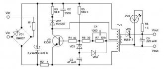
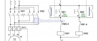
Switching voltage converter MC34063
It didn’t take long to choose a driver for the voltage converter, since there wasn’t much to choose from. At the local radio market, at a reasonable price ($0.4), I found only the popular MC34063 chip. I immediately bought a couple to find out if it was possible to somehow forcibly turn off the converter, since the datasheet for this chip does not provide for such a function. It turned out that this can be done by applying supply voltage to pin 3, intended for connecting the frequency-setting circuit.
The picture shows a typical circuit of a step-down pulse converter. The forced shutdown circuit, which may be needed for automation, is marked in red.
In principle, having assembled such a circuit, you can already power your phone or player if, for example, the power is supplied from ordinary batteries (batteries).
I will not describe in detail the operation of this chip, but from the “Additional Materials” you can download both a detailed description in Russian and a small portable program for quickly calculating the elements of a boost or buck converter assembled on this chip.
A little theory
I think there is no point in explaining what wireless phone charging is.
After all, this is obvious - this is the most common charger that works wirelessly. But the question of how it works will be very interesting. Therefore, it is worth diving a little into the theory and the initial course of physics. The technology is based on the use of induction coils. They can work both as a transmitter and as a receiver of inductive energy. That is, in simple terms, one coil is connected to the power supply. It gets excited and creates a magnetic field around itself. The second coil, falling within the range of this magnetic field, also begins to be excited and generate an electric charge.
Everything is quite simple and clear. From the above, it becomes clear that a wireless charger does not allow you to walk around with your phone in your hands while charging. That is, the restrictions that exist in wired chargers also apply to wireless chargers.
Moreover, the wire can be quite long (up to 5 meters) and you can easily move within this radius. But the magnetic field generated by the inductive coil, as a rule, does not exceed 5 cm. Therefore, the only advantage of such a device is that you will not break the microUSB connector itself.
And here it is a rather controversial question whether the idea is worth it. In principle, replacing the microUSB connector in your phone is quite easy and cheap. And if it is of high quality, it will last quite a long time.
Therefore, purchasing or manufacturing a wireless charger just for the purpose of saving money will not be profitable. Another question is if everything depends on aesthetics or reluctance to constantly deal with wires: then let’s get down to action. Essentially, wireless charging for Android is just a convenient stand for your phone that looks attractive and charges the battery at the same time.
Mobile phone charger
Let's try to assemble a slightly more complex, but more convenient memory. The batteries built into miniature mobile multimedia devices usually have a small capacity, and, as a rule, are designed to play audio recordings for no more than several tens of hours when the display is turned off, or to play several hours of video or several hours of reading e-books. If a power outlet is unavailable or the power supply is turned off for a long period of time due to bad weather or other reasons, then various mobile devices with color displays will have to be powered from built-in energy sources. Given that such devices consume considerable current, their batteries may be discharged before electricity is available from a wall outlet.
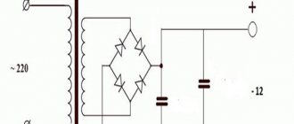
If you do not want to immerse yourself in primitive silence and peace of mind, then to power your handheld devices, you can provide a backup autonomous energy source, which will help out both during a long journey into the wild, and in case of man-made or natural disasters, when your settlement may be on the verge of destruction. several days or weeks without power supply. Scheme of a mobile charger without a 220V network The device is a linear voltage stabilizer of a compensation type with a low saturation voltage and a very low intrinsic current consumption.
Mobile phone charger with different plugs.
The energy source for this stabilizer can be a simple battery, rechargeable battery, solar or manual electric generator. The current consumed by the stabilizer when the load is off is about 0.2 mA at an input supply voltage of 6 V or 0.22 mA at a supply voltage of 9 V. The minimum difference between the input and output voltage is less than 0.2 V at a load current of 1 A! When the input supply voltage changes from 5.5 to 15 V, the output voltage changes by no more than 10 mV at a load current of 250 mA. When the load current changes from 0 to 1 A, the output voltage changes by no more than 100 mV at an input voltage of 6 V and by no more than 20 mV at an input supply voltage of 9 V.
It will be interesting➡ Options for connecting circuits for pass-through switches
A self-resetting fuse protects the stabilizer and battery from overload. The reverse-connected diode VD1 protects the device from reverse polarity of the supply voltage. As the supply voltage increases, the output voltage also tends to increase. To maintain the output voltage stable, a control unit assembled at VT1, VT4 is used. An ultra-bright blue LED is used as a reference voltage source, which, while performing the function of a micro-power zener diode, is an indicator of the presence of output voltage.
When the output voltage tends to increase, the current through the LED increases, the current through the emitter junction VT4 also increases, and this transistor opens more, and VT1 also opens more. which bypasses the gate-source of the powerful field-effect transistor VT3. As a result, the resistance of the open channel of the field-effect transistor increases and the voltage across the load decreases.
Trimmer resistor R5 can be used to adjust the output voltage. Capacitor C2 is designed to suppress self-excitation of the stabilizer as the load current increases. Capacitors C1 and SZ are blocking capacitors in the power supply circuits. Transistor VT2 is included as a micro-power zener diode with a stabilization voltage of 8..9 V. It is designed to protect against breakdown of the VT3 gate insulation by high voltage. A gate-source voltage that is dangerous for VT3 may appear when the power is turned on or due to touching the terminals of this transistor.
Do-it-yourself charger.
The KD243A diode can be replaced by any of the KD212, KD243 series. KD243, KD257, 1N4001..1N4007. Instead of KT3102G transistors, any similar ones with low reverse collector current are suitable, for example, any of the KT3102, KT6111, SS9014, BC547, 2SC1845 series. Instead of the KT3107G transistor, any of the KT3107, KT6112, SS9015, VS556, 2SA992 series will do. A powerful p-channel field-effect transistor of the IRLZ44 type in a TO-220 package, has a low gate-source opening threshold voltage, a maximum operating voltage of 60 V. The maximum constant current is up to 50 A, the open channel resistance is 0.028 Ohm. In this design, it can be replaced with IRLZ44S, IRFL405, IRLL2705, IRLR120N, IRL530NC, IRL530N. The field-effect transistor is installed on a heat sink with a cooling surface area sufficient for a particular application. During installation, the terminals of the field-effect transistor are short-circuited with a jumper wire.
The autonomous charge device can be mounted on a small printed circuit board. As an autonomous power source, you can use, for example, four pieces of series-connected alkaline galvanic cells with a capacity of 4 A/H (RL14, RL20). This option is preferable if you plan to use this design relatively rarely. If you plan to use this device relatively often or your player consumes significantly more current even when the display is off, then it would be advisable to use a 6 V rechargeable battery, for example, a sealed motorcycle battery or from a large hand-held flashlight.
You can also use a battery of 5 or 6 nickel-cadmium batteries connected in series. When hiking, fishing, to recharge batteries and power a handheld device, it may be convenient to use a solar battery capable of delivering a current of at least 0.2 A with an output voltage of 6 V. When powering the player from this stabilized energy source, it should be taken into account that the regulating transistor is turned on into the negative circuit, therefore, simultaneous power supply of the player and, for example, a small active speaker system is only possible if both devices are connected to the stabilizer output.
Interesting read: How to test a battery using a multimeter.
Qi standard
Wireless energy transfer was of interest to many areas of human life, but for a long time did not go beyond the walls of laboratories. Already in this century, companies that develop consumer electronics (tablets, smartphones) began to take initiatives to create wireless chargers. A huge contribution was made by the Wireless Power Consortium, which developed the Qi standard for low currents.
The standard specification was free and accessible, so it very soon began to be used in portable equipment. Three years later, Qi acquired a specification for medium currents. There are other standards, but they are more complex than Qi and less widespread. More recently, in 2015, scientists at the University of Washington discovered that energy can be transmitted via Wi-Fi networks. We are waiting for the smartphone to charge by connecting to the router.
Block diagram
The portable memory consists of the following components.
- Converter 5 → 14 Volt.
- A comparator that turns off the charge converter when the voltage on the lithium-ion battery reaches 12.8 Volts.
- Charge indicator – LED.
- Converter 12.6 → 5 Volts.
- A 7.5 Volt comparator that turns off the charger when the battery is deeply discharged.
- A timer that determines the operating time of the converter when the battery is critically discharged.
- Converter operation indicator 12.6 → 5 Volts - LED.
Disadvantages of homemade BZU
The main disadvantage is that such a charger does not allow you to use the phone while charging. That is, you will not be able to move the gadget further than 5 cm from the WZU (wireless charger).
You will also have to disassemble your smartphone or tablet yourself and add a circuit with a coil, albeit a small one, to the case. Of course, it goes without saying that after such actions there can be no question of any guarantee. And there is a risk that you will simply damage the device.
Another disadvantage is that such generators and transmission circuits create fairly strong magnetic fields (albeit with a short range), which can interfere with the power supply or for speaker systems (if they are located near speakers or an audio amplifier).
In addition, such homemade devices have a rather low level of efficiency (efficiency factor). That is, the charging speed will be quite low, while the electricity consumption will remain the same (even a little higher).
Is it worth making such a device? It's a matter of personal preference. If you are driven by curiosity and a thirst for experimentation, then it is quite possible to do everything with an old phone that you no longer mind. If you need savings, aesthetics and convenience, then it is better to use a regular charger or buy phones that already support a charger from the factory.