The mechanical design of a wind generator in its pure form is only part of a complete wind power plant. A fully usable system, in addition to the mechanical structure, also has a number of electronic components.
For example, a controller for a wind generator is required - a device functionally designed to stabilize the battery charge parameters during the operation of the wind turbine.
Let's figure out what functions the device performs and provide diagrams for assembling the controller yourself. In addition, we will outline the features of the work and the advisability of purchasing a Chinese electronic unit for a windmill.
Balancing board for li-ion battery 18650
What is the function of the balancer in lithium batteries? If several cells are connected in series, their voltage adds up to a total sum, and the battery capacity is equal to the lowest of all cells.
To prevent the laziest part from overcharging, it is disconnected from power, allowing the remaining parts to continue charging. The balancer controls the uniformly distributed charge, so it is included in circuits with a series connection of elements. With a parallel connection, there is no need for balancing: there is an even charge distribution. The balancing board is usually included in the general protective housing of the MBS and is called a “balancing cable”.
Precautionary measures
When using self-assembled devices, the following safety precautions should be observed:
- All devices, including the battery, must be on a fire-resistant surface.
- When using the manufactured device for the first time, it is necessary to ensure full control of all charging parameters. It is imperative to control the heating temperature of all charging elements and the battery; the electrolyte should not be allowed to boil. The voltage and current parameters are controlled by a tester. Primary monitoring will help determine the time it takes to fully charge the battery, which will be useful in the future.
Assembling a battery charger is easy even for a beginner. The main thing is to do everything carefully and follow safety measures, because you will have to deal with an open voltage of 220 volts.
I’m replacing the controller’s PIC with my favorite AVR, the 7-segment indicators with the iconic LCD, and I’m also finalizing the program code in terms of expanding the functionality regarding calibrations and other little things.
Well, fellow solders, let’s take the article, some pieces of iron, a soldering iron and let’s go!
:bye:
Why does the charge drop?
All batteries have a certain capacity, stated in Ah. In passenger cars, batteries of 60-80 Ah are most often found. That is, at 60 Ah, the device can produce a current of 1 Ampere for 60 hours. But this is in theory.
In practice, everything is different. As soon as the engine starts, the charge drops significantly. But it is compensated by the operation of the generator. Not all drivers drive a lot and often, and therefore the generator simply does not have time to replenish the entire charge. It has been proven that in most cases, cars are operated with constant undercharging.
Capacity can decrease under the influence of various factors:
- poor fastening, mechanical damage;
- electrical problems;
- violation of the integrity of electrical wiring;
- sulfation processes;
- driving around the city on short trips;
- low ambient temperature, etc.
Since most drivers drive in such conditions, it is imperative to periodically check the condition and charge of the battery.
Circuit diagram of a simple charger for a car battery
The formula for a normal charge is as simple as 5 kopecks - the basic battery capacity divided by 10. The charging voltage should be a little over 14 volts (we are talking about a standard 12 volt starter battery).
A simple circuit diagram of a car charger consists of three components: power supply, regulator, indicator.
Classic - resistor charger
The power supply is made of two winding “trans” and a diode assembly.
The output voltage is selected by the secondary winding. The rectifier is a diode bridge; a stabilizer is not used in this circuit. The charging current is controlled by a rheostat. Important! No variable resistors, even those with a ceramic core, will withstand such a load.
A wire rheostat is necessary to counteract the main problem with such a circuit - excess power is released in the form of heat. And this happens very intensively.
Of course, the efficiency of such a device tends to zero, and the service life of its components is very low (especially the rheostat). Nevertheless, the scheme exists, and it is quite workable. For emergency charging, if you don’t have ready-made equipment at hand, you can literally assemble it “on your knees.” There are also limitations - a current of more than 5 amperes is the limit for such a circuit. Therefore, you can charge a battery with a capacity of no more than 45 Ah.
DIY charger, details, diagrams - video
Quenching capacitor
The operating principle is shown in the diagram.
Thanks to the reactance of the capacitor included in the primary winding circuit, the charging current can be adjusted. The implementation consists of the same three components - power supply, regulator, indicator (if necessary). The circuit can be configured to charge one type of battery, and then the indicator will not be needed.
The highlight of the charger is the capacitor battery. The peculiarity of circuits with a quenching capacitor is that by adding or decreasing capacitance (simply connecting or removing additional elements) you can regulate the output current. By selecting 4 capacitors for currents of 1A, 2A, 4A and 8A, and switching them with ordinary switches in various combinations, you can adjust the charge current from 1 to 15 A in 1 A steps.
At the same time, there is no parasitic heating (except for the natural one generated by the bridge diodes), the efficiency of the charger is high.
↑ Logic of the program
The operating logic is simple and consists of 4 stages: STEP 1 - discharge the battery to a voltage of 10.7V; STEP 2 - charge the battery to a voltage of 15V; STEP 3 - discharge the battery to a voltage of 10.7V; STEP 4 - charge the battery to a voltage of 15V. — At each stage, time is measured. — The voltage on the battery is controlled. — You can skip unnecessary steps by going straight to step 2, 3 or 4. — The main indicator of the battery condition will be the capacity measured in the third step.
If the contact with the battery is lost or the terminals are short-circuited, the device will stop working and display an “ERROR” error.
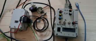
Assembly and testing
The case is selected individually. You can glue it yourself from plastic, or buy something more or less suitable. The locations for the output of LEDs and manual control buttons are determined after fixing the board. If desired, you can make a hole for a trim resistor.
Do not try to immediately take a very small case.
To test the battery charge controller, you will need an adjustable DC\DC converter, which will simulate the voltage at the battery terminals.
The normally open output of the relay is connected to the multimeter in dial mode.
When the battery is charged and the load is connected to it, the multimeter emits a continuous signal, and the blue LED lights up on the controller.
As soon as the voltage drops below the set limit, charging starts. The red LED on the charge controller lights up, and the indication on the multimeter display changes.
That's it, the battery charge controller is ready, you can use it.
You might also like the following materials:
Thank you for reading to the end! Also Don't forget if you liked the article!
Follow us on Twitter:
Share with friends, leave your comments
Add to our group on VK:
ALTER220 Portal about alternative energy
and suggest topics for discussion, together it will be more interesting!!!
Indication of symbols on the display
- V - measured voltage on battery
- Vs(max) - voltage up to which the charge will be made
- Vmin(m) - minimum voltage on the battery at which the discharge will be turned off
- I - measured charge current
- Is - set charge current
- Id—measured discharge current
- Ii - discharge current set in the menu (discharge current stabilization)
- Imin - minimum current at which the charge will be completed
- H - timer time. For all modes.
- Hi - remaining time before shutdown by timer
- P -capacitance AB-Ah
- LED backlight
1.When the device is connected to the network, display information if the battery is connected
1.1. Voltage to which the charge will be made. Default Vs=14.2 (Selection range in the menu is 1-30 volts.)
1.2.Set charge current. By default Is=0.5A. (selection range in the menu 0.5 -10A. resolution 0.5A.)
1.3. Real voltage on the battery. For example - V=13.7
1.4.Default mode - charging (the mode can be changed in the menu. Names of modes. charge . discharge. kts battery.)
MODE 1.charge
If the battery is not connected, instead of voltage on the battery, display the inscription - no bat. Everything else is the same as when the battery is connected.
Example 1.0. battery not connected
Vs=14.2 Is=0.5A ? Battery Charge
When you press the start button, start the set mode. When pressed again, stop. when the mode is running, the name of the selected mode flashes. When stopped, it lights up constantly.
Example 1.1. battery is connected.
Vs=14.2 Is=0.5AV=13.7 Charge
When the mode is running, instead of the set voltage to which the charge will be made, the real charge current is displayed. Example I = 3.6 A
Example 1.2. charging is in progress.
I=3.6A Is=0.5AV=13.7 charge
After the charging is complete (by a timer or when the set voltage on the battery is reached or the charging current drops to I=min), turn off the charge and remove it - the charge is turned off.
If the charging current exceeds the one set in the menu. And also the voltage on the battery exceeded the one set in the menu - turn off the charge and display the inscription - ERROR.
MODE 2. digit
2. When selecting the discharge mode (when starting this mode, automatically charge the battery to the set voltage and then start discharging.
Example 2.0. Indication in the main mode window. If the mode is not running, the name of the mode (digit) does not blink. When the mode is running, the name of the mode currently used (charge or discharge) flashes.
If the mode is running. AB is not charged. There is an automatic charge, after which the discharge will begin.
I=0.5A charge P=0Ah
2.1 Default discharge current Id = 0.5 A. Selection range in the menu 0.5-10 A. resolution 0.5 A.
2.2. Hi — Time remaining until the end of the discharge, after which the discharge will be disabled by default.
2.3. Measured battery capacity P=????Ah (example P = 45.4Ah). Example 2.1. window during discharge
Id=0.5A Hi=10 P=45.4Ah discharge
After the end of the discharge, give a signal with a pause of 1 second. And so on until another mode is turned on. Apply the signal to pin 4 of the MK. LED out. Display the inscription at the top - P=????Ah. Vm=11.0 at the bottom - OFF digit.
Example 2.2. the discharge is over
P=100.3Ah Vm=11.0 Discharge off
MODE 3. Kts battery. Desulfation.
In the main mode window, if the mode is running, the mode name (KTC) flashes. If it is not running, it does not blink.
3.1. The default charge current is Is = 5A. Range 0.5-10 A
3.2. Discharge current Id = 0.5A. Range 0.5-10 A.
3.3. Voltage on the battery. Frequency 1 Hz.
Example 3.0. desulfation occurs.
I=5.0A Id=0.5A V=14.2 KTTs-AB
After the charging is completed (by a timer or when the set voltage is reached, turn off the mode), display the message - CTC OFF. And the voltage on the battery.
Example 3.1. end of work.
V=14.7 CTC OFF
Discuss the article CAR CHARGER ON CONTROLLER
↑ Technical characteristics
I initially tried to write the program as universal as possible. After reading about the implementation of EEPROM-based calibration from Alexander’s article, I decided to create a special calibration menu because LCD allows you to draw and show everything beautifully. — Maximum timer time: up to 100 hours. — Voltage calibration range: 3.0 – 20.0 V, step 100 mV. — Charge/discharge current calibration range: 100 – 10,000 mA, 1 mA step. — Maximum charge/discharge current: limited by LM317, 1.5A. (you can add a powerful transistor with increased power resistors R1 and R9, which will increase it up to 10A).
Pulse chargers
Pulse chargers have a number of advantages:
What kind of alarm system with auto start is better to install on a car? - there is more useful information here.
- high efficiency, as a result, lower energy consumption and heating during operation;
- smaller dimensions and weight compared to transformer devices;
- the ability to automate control of basic charge parameters;
- Greater manufacturability in manufacturing.
The main disadvantages of pulse chargers:
- high probability of failure of powerful transistors;
- the need for deep knowledge in electrical engineering to configure devices;
- the absence of galvanic isolation from the supply voltage reduces the degree of electrical safety;
- high level of electromagnetic interference (they cannot be turned on in close proximity to radio devices or mobile equipment).
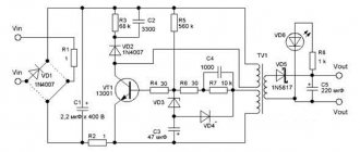
One of the simplest variants of the electrical circuit is shown in Figure 8.
You might be interested in this article - How to use a torque wrench for a car?
The operating principle of pulse devices is based on converting alternating voltage from a household electrical network into direct voltage using a VD8 diode assembly. The DC voltage is then converted into pulses of high frequency and amplitude. Pulse transformer T1 again converts the signal into DC voltage, which charges the battery.
Since the reverse conversion is carried out at a high frequency, the dimensions of the transformer are much smaller. The feedback necessary to control the charge parameters is provided by optocoupler U1.
Despite the apparent complexity of the device, when assembled correctly the unit begins to work without additional adjustment. This device provides a charging current of up to 10 Amps.
General recommendations
When charging the battery using a homemade device, you must:
- place the device and battery on a non-conductive surface;
- comply with electrical safety requirements (use gloves, a rubber mat, tools with an electrical insulating coating);
- Do not leave the charger turned on for a long time without control, monitor the voltage and temperature of the battery, and the charging current.
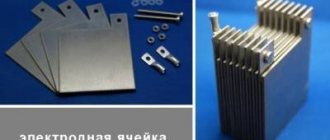
Li-ion battery 18650 device
The lithium-ion battery charging controller is produced by corporations: Sony, LG, Sanyo, Panasonic, Samsung, ATL, HYB. Other manufacturers repurchase the elements and pass them off as their own product.
Maximum capacity of ion batteries 18650 – 3600 mAh; they, unlike batteries, can be recharged many times. The number 18650 is a form factor indicating the length of the battery (65 mm) and its diameter (18 mm).
Key Features of 18650 Li-ion Battery:
- the maximum permissible voltage is 4.2 V (small overcharges have a detrimental effect on service life);
- the minimum permissible voltage is 2.75 V (if it drops to 2 V, the charge cannot be restored);
- the minimum permissible temperature is –20 ° C (it is impossible to charge in the cold);
- maximum permissible temperature +60 °C (if the indicators are exceeded, explosion and fire are possible);
- Capacity measurement in ampere hours - a full charge produces 1 A of current for 60 minutes, 2 A of current for 30 minutes, 15 A of current for 4 minutes.
A lithium-ion battery converts chemical energy into electrical energy, creating a current that powers a device. Such batteries are equipped with a special protective circuit that controls the level of its heating and operating cycles. If it overheats and the voltage drops to 2.7 V, the controller automatically stops operating the battery.
Li-ion batteries are very explosive, so they have built-in protective circuit boards. A deep discharge of such batteries occurs after 2–3 years of non-use, after which they are problematic to restore and do not have a long service life
Previous experience
Up to this point I have been using LT4054 controllers, and to be honest, I was pleased with them:
• It allowed charging compact Li-Pol batteries with a capacity of up to 3000 mAh
• Was ultra-compact: sot23-5
• Had a battery charging indicator
• Has a bunch of protections, which makes it a practically indestructible chip
Figure 2. Board with Li-Ion charge controller on LTC4054
An additional advantage is that before I started doing anything with it, I bought 50 of them, at a very modest price.
I identified shortcomings in the work, and, frankly speaking, they put me in a partial stupor:
• The maximum declared current is 1A, I thought. But already at 300 mA during charging, the chip warms up to 110 * C, even in the presence of large radiator polygons and a radiator attached to the plastic surface of the chip.
• When the thermal protection is turned on, a comparator appears to be triggered, which quickly resets the current. As a result, the microcircuit turns into a generator, which kills the battery. This way I killed 2 batteries until I figured out what was wrong with the oscilloscope.
• In view of the above, I got a problem with the device charging time of about 10 hours. Of course, this greatly dissatisfied me and the consumers of my electronics, but what can I do: everyone wanted to increase the service life with the same parameters of the device, and sometimes they consume a lot.
In this regard, I started looking for a controller that would have much better parameters and heat dissipation capabilities, and my choice so far has settled on the MCP73833, mainly due to the fact that my friend had these controllers in stock, and I whistled a couple of pieces quickly( faster than him) soldered the prototype and carried out the tests I needed.
Circuit diagram of a capacitor charger without automatic shutdown
For those who do not have sufficient experience in assembling electronic circuits or do not need to automatically turn off the charger after charging the battery, I offer a simplified version of the circuit diagram for charging acid-acid car batteries. A distinctive feature of the circuit is its ease of repetition, reliability, high efficiency and stable charging current, protection against incorrect battery connection, and automatic continuation of charging in the event of a loss of supply voltage.
The principle of stabilizing the charging current remains unchanged and is ensured by connecting a block of capacitors C1-C6 in series with the network transformer. To protect against overvoltage on the input winding and capacitors, one of the pairs of normally open contacts of relay P1 is used.
When the battery is not connected, the contacts of relays P1 K1.1 and K1.2 are open and even if the charger is connected to the power supply, no current flows to the circuit. The same thing happens if you connect the battery incorrectly according to polarity. When the battery is connected correctly, the current from it flows through the VD8 diode to the winding of relay P1, the relay is activated and its contacts K1.1 and K1.2 are closed. Through closed contacts K1.1, the mains voltage is supplied to the charger, and through K1.2 the charging current is supplied to the battery.
At first glance, it seems that relay contacts K1.2 are not needed, but if they are not there, then if the battery is connected incorrectly, current will flow from the positive terminal of the battery through the negative terminal of the charger, then through the diode bridge and then directly to the negative terminal of the battery and diodes the charger bridge will fail.
The proposed simple circuit for charging batteries can be easily adapted to charge batteries at a voltage of 6 V or 24 V. It is enough to replace relay P1 with the appropriate voltage. To charge 24-volt batteries, it is necessary to provide an output voltage from the secondary winding of transformer T1 of at least 36 V.
If desired, the circuit of a simple charger can be supplemented with a device for indicating charging current and voltage, turning it on as in the circuit of an automatic charger.
What is the battery controller for?
Despite the fact that the capacity of modern batteries, as well as their functionality, has increased significantly, the charging algorithm has remained virtually unchanged. When the battery is discharged, special equipment is connected to it, which, by stimulating chemical reactions in the battery, replenishes its capacity.
Important! If you do not stop charging in a timely manner, the battery may overheat and even explode. In a situation where there is not enough current to replenish the charge, the battery cannot restore its capacity; being in a discharged state for a long time can significantly reduce its service life
In order for all processes to occur correctly, and the battery built into the mobile device to work as long as possible, a battery charge controller is needed. At its core, as a rule, there are two resistors that control the upper and lower voltage limits. At the very beginning of energy replenishment, they pass the maximum current through themselves, then they gradually reduce it, protecting the battery from overcharging. If the voltage is below the minimum required, the resistor supplements it to the required level using previously accumulated energy.
A battery charge controller is required in laptops, mobile phones, portable cash registers, tablets, and so on. It is also installed in renewable energy sources, since the principle of their operation is to accumulate energy in a special battery during periods of solar or wind activity, and then transfer it to the consumer. To control these procedures, the described element is needed in this equipment.
Using devices to monitor battery charge
↑ Some lyrics
I have long wanted to assemble a device for testing 12V/7Ah batteries, because... There are a lot of them at work, and the quality of purchased batteries does not always reach an acceptable level. And suddenly I came across a datagor article from koan51. The idea of the device is simple: charge and discharge the battery with a fixed current, measuring time during operation while controlling the voltage. Knowing all three quantities, you can measure the current using a simple formula - time multiplied by current. I sketched out a diagram based on Alexander’s article.
Read also: Timer 555 operating principle
Charging from USB port
You can make a charger for nickel-cadmium batteries based on a regular USB port. At the same time, they will be charged with a current of approximately 100 mA. The scheme, in this case, will be as follows:
At the moment, there are quite a lot of different chargers sold in stores, but their cost can be quite high. Considering that the main point of various homemade products is precisely to save money, self-assembly is even more advisable in this case.
This circuit can be modified by adding an additional circuit to charge a pair of AA batteries. Here's what we ended up with:
To make it more clear, here are the components that were used during the assembly process:
It is clear that we cannot do without basic tools, so before starting assembly you need to make sure that you have everything you need:
- soldering iron;
- solder;
- flux;
- tester;
- tweezers;
- various screwdrivers and knife.
Interesting material about making it yourself, we recommend viewing it
A tester is necessary to check the performance of our radio components. To do this, you need to compare their resistance, and then check it with the nominal value.
For assembly we will also need a case and a battery compartment. The latter can be taken from the children's Tetris simulator, and the body can be made from a regular plastic case (6.5cm/4.5cm/2cm).
We attach the battery compartment to the case using screws. The board from the Dandy console, which needs to be cut out, is perfect as a basis for the circuit. We remove all unnecessary components, leaving only the power socket. The next step is to solder all the parts based on our diagram.
The power cord for the device can be taken from a regular computer mouse cord with a USB input, as well as part of the power cord with a plug. When soldering, polarity must be strictly observed, i.e. solder plus to plus, etc. We connect the cord to USB, checking the voltage supplied to the plug. The tester should show 5V.
Finally, you need to set the charging current. To do this, you need to break the circuit connecting VD1 and the positive polarity of the battery. We connect the tester in such a way that its plus is connected to the diode, and its minus is connected to the battery. We set the current measurement mode (200 mA).
We turn it on, after which the LED should light up, of course, if everything is done correctly. Then we set the required charging current (100 mA) by changing the resistance on resistor R1. We carry out this procedure for the second AA battery.
Another interesting video on this topic
What's next?
And then I’m going to implement this chip into my various device ideas. For example, a trial version of a development board based on STM32F103RCT6 and 18650 batteries is currently being produced at the factory. I already have a development board for this controller, which has proven itself very well, and I want to complement it with a portable version so that I can take my work project with me and not think about power and searching for a socket into which to insert the power supply.
I will also use it in all solutions that require charging currents of more than 300mA.
I hope you will be able to use this useful and simple chip in your devices.
If you are at all interested in battery power, here is my personal video about battery power for devices.
A simple DIY solar battery controller
People who understand electronics often try to assemble controllers for solar systems themselves. They succeed, but the efficiency of such mechanisms is still inferior to factory ones. However, for small installations a small device with low power is quite sufficient.
When making a homemade charge controller, you should keep in mind that:
- The charger voltage should be 13.8 Volts and vary depending on the current rating;
- The voltage when charging is turned on is usually 12.5 Volts;
- And when turned off - 11 Volts (as a rule, this parameter is adjusted manually);
- The highest input voltage of the device should be equal to the total voltage of the batteries without load;
- At a current of 0.5 A, the voltage drop across the keys should be 20 mV.
Battery CTC mode
When the program starts, the battery charge with current Is is turned on. After 1 second, the battery switches to a discharge with current Ii. After another 1 second, the battery switches to charging again. This continues until the voltage reaches Umax - the program stops. CTC indication off. If the voltage rises above Umax by 0.2, the program stops, ERROR is displayed. If the charge or discharge current exceeds the set value by 0.2, the program stops, ERROR is displayed.
If the charging time has expired (parameter H), the program stops, ERROR is displayed in the top line. The bottom line says Time out.
The selected mode is not remembered after disconnecting from the network. When turned on, it is always in charging mode.