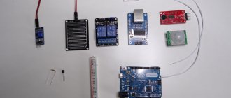
This review identifies 10 common applications for controlling Arduino from a computer or phone that are easy to learn and use. Arduino is a platform designed in view of modern programming technologies. Board with USB connectors for power supply. When connected to a PC, it charges. The internal system has a button to format the data.
Main components:
- Bradboard – connects the platform to the device.
- The LED is an indicator that signals control.
- Resistor - controls the flow of electrical current within the platform.
- Photoresistor - reacts to the type of lighting.
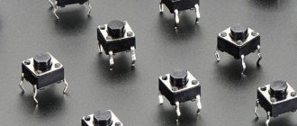
- Transistor – amplifies electrical signals and is used in complex circuits.
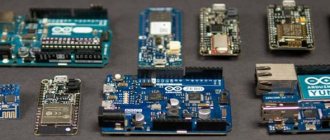
This was an internal description. Next we move on to a review of the application itself. Google has created a new application programming interface called Arduino. Designed to connect an Android device to USB. Opens up great opportunities for creating projects and simplifies programming and control from the mobile phone screen. Helps manage data synchronization.
Overview of Arduino features:
- creating sketches;
- editing, compiling and loading them on the board;
- programming and code development.
The work is done from a smartphone from any part of the globe. This review will describe programs developed for remote use of Arduino, namely Bluetooth and Wi-fi controllers. They are easy to use and allow you to work from any gadget. The Arduino project consists of 3 stages:
- writing code;
- prototyping;
- firmware.
To program these functions, you need to write code that can be deleted as needed and flash the development environment. This is a multi-step process. Several programs participate in it.
Arduino Bluetooth Controller
This program works in 3 main positions:
Controller. The application is displayed in the form of a play identifier and is controlled by switch buttons. It operates with one key, the main function of which is remote control.
Dimmer. From a distance, adjusts brightness and speed settings.
Terminal. Implementation of sending directive for decryption.
Installing the Arduino Bluetooth Controller app connects multiple devices over the air. Messages are transmitted to sensors, controllers and back. By controlling a smartphone using Bluetooth modules, it is also possible to organize a wireless connection for an entire project. Programming of this type is accessible to everyone and does not require much effort.
VOICE CONTROL VIA SMARTPHONE
For the fourth point, I used another wonderful app - Utter!
Voice Commands Beta because it integrates with Tasker and can perform its tasks by voice command. But setting it up simply requires angelic patience. The procedure is simple: despite the requirement of Utter! install Russian voice search language for Android. Then we open the Utter interface! (what is important is not the recognition of commands, but the program interface) - Customization - Create commands - Run Tasker Task - select a task and try to pronounce the command the same way twice in a row. If it works, don’t relax and say two more words: for successful execution of the command and for errors.
If Utter! doesn’t understand at all, then you can leave the search engine in English and find any word/phrase that you can pronounce twice in a row the same way. The same applies to confirmation and error messages. Then just go to the Edit commands item and replace the texts with the ones you need. Just remember that Utter! cannot speak Russian, and therefore it is better to write confirmation and error messages in English or in transliteration.
Yes, we are not afraid when Utter! when repeating a command in Russian, he does not pronounce it. This, again, is a consequence of the fact that the app does not know how to use the Russian voice engine.
In general, the task is dreary, but solvable.
ArduinoDroid - Arduino IDE
Used by programmers as a means of editing codes and creating programs. Feature - the written sketch is converted into CC+, compiled and loaded into Arduino. Great for those new to the field. The application can be used free of charge and in the public domain.
The first step in use will be to upload the sketch to the microcontroller. Next, by clicking the “Download” button, you must wait for the download to complete. A flashing LED means everything was done correctly. Everything is ready to write and use firmware.
ArduinoDroid is easy to use software. Edits, compiles and uploads codes to the board from a mobile device or tablet. It is also recommended to edit the cipher or upload a ready-made one if the program is banned..
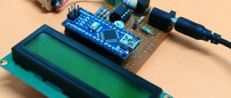
Final result
If you wrote down the code correctly, with the correct password and name from your wifi, which is working properly, then a link will be sent to the port monitor, which must be pasted into the address bar of the browser. The image should look like this
And now you can connect the Arduino to the power source and remove the Arduino-computer connection wire. And find out the temperature in your house, being on the other side of the city. It all depends only on your imagination.
Next time we’ll try to look at another project that will help to better reveal all the capabilities of the Internet module. In the future, we will try to create our own server and website, and also talk about connecting to social networks. Increase your ability to make your home smart.
RemoteXY: Arduino Control
This Arduino control program allows you to create a personal panel. Remote control occurs via:
- Internet;
- Wi-Fi;
- IR port;
- Bluetooth.
On the page https://remotexy.com you can find and download many interesting instructions. For example, how to create original keys and switches. The functionality is adapted for beginners and will not create problems in use.
Controlling Arduino from a computer, namely RemoteXY, is possible via the cloud. This makes it superior to similar Russian Arduino software.
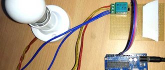
Schematic diagram
Let's connect the Ethernet shield to the Arduino motherboard. And the electromagnetic relay is already connected to the expansion board. We use 5 volt power and ground. And to control the relay, we’ll take digital pin 7.
Schematic diagram of connecting Ethernet shield and relay
Blynk app
A sort of idea developer with an open door to launch on the Arduino platform. The main requirement for use is the presence of the Internet: Wi-Fi or mobile traffic. Only in this case will Blynk be ready for execution. You can start using it a few minutes after completing the settings. The program supports the AO of the user's choice.
The main functions of the Blynk application are to manage devices by removing and adding HTTP protocols, as well as GET and POST requests. Parameter values can be updated and retrieved. Requests are updated in the application itself.
Variability is an important point of the program. Having a connection with running platforms, you can connect to the server in any convenient way. This instinctive portal is easy to use on a project. The library is constantly updated for all Arduino Blynk applications.
Customers who want to turn on the coffee machine from their smartphone will be interested in this application. This is perhaps the only service with such capabilities. And despite the fact that it is practically unlimited, Openhab is difficult. Compared to other services, it has fast startup speed.
FEATURES OF CHINESE TRADE
Be careful, sellers on Aliexpress have a very bad habit of writing something like 2pcs in the product name, which seems to hint that these are two pieces of the item for the specified price.
But this is a little different, and is designed to stimulate impulse purchases. For example, in the description of the Arduino Uno board it is written that “UNO R3 MEGA328P ATMEGA16U2 + USB Cable (1UNO R3 + 1 cables) Best prices & Free shipping!!!”, the price is $9.98 and it is added that this is a lot (2 pieces/lot) .
At first glance it seems that these are TWO (profit!!!) Arduino Uno boards. But in fact, behind 2 pieces/lot lies exactly what is written in the title and, a little lower in the description (to the credit of the Chinese - in huge letters). Exactly:
— Arduino Uno — 1 piece — USB cable — 1 piece Total: TWO pieces
Those. in this case, one lot is a board + cable. The only excuse for the seller is that the price is average in the market.
What else did I not like about this order? Out of a set of two relays, only one block came. The seller responds sluggishly, for a long time, but in the end he agreed to send the second block.
Otherwise everything is tolerable. Delivery took about a month, the packaging was a rather hard cardboard box wrapped with tape. Everything inside is in antistatic bags, the Ethernet shield is pinned onto polypropylene (?) pads so that the contacts do not bend.
Everything arrived in good condition. But taking into account some kind of inhibition of the seller, and even these relays, I don’t think that I will buy anything else from him.
Bluino Loader – Arduino IDE
Software for compiling code into a file and uploading it to the Arduino platform via smartphone and USB OTG. Bulky buttons and tangled wires make projects much more difficult. For simplified remote administration control, a Bluino Loader IDE graphical ID is provided. Develops projects available to the trigger. Connects to the World Wide Web using: Wi-Fi, Ethernet or via an ESP8266 drive. When the necessary procedures are completed and work starts, the application will give a signal.
Setting up the software to create projects will take no more than 5 minutes. The software is configured according to the user's choice. Simple and convenient software. To check, upload the sketch to the microcontroller and make sure that everything works as it should. A flashing diode will signal that the actions performed are correct. Next we proceed to the firmware.
Program
The meaning of the project is the same as with bluetooth. The board must receive a signal from us and set the relay to the desired state. Then the equipment connected to the relay will turn on or off accordingly.
Let's use an example from the Ethernet library.
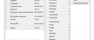
Open the sketch from the File Menu -> Examples -> Ethernet -> WebServer
Libraries and
You can set the mac address and ip address for your board. The IP address must be suitable for your local network. The HTTP server will work on port 80 as usual. And we will connect the relay to pin 7.
// Enter a MAC address and IP address for your controller below. // The IP address will be dependent on your local network: byte mac[] = { 0xDE, 0xAD, 0xBE, 0xEF, 0xFE, 0xED }; IPAddress ip(192, 168, 0, 177); EthernetServer server(80); int RelayPin = 7;
In the setup() we configure all the necessary functions for working via the Internet. And uncomment the line Ethernet.init(10);
// You can use Ethernet.init(pin) to configure the CS pin Ethernet.init(10); // Most Arduino shields
Let's configure the pin for the relay to output and turn it off.
// start the server server.begin(); Serial.print("server is at "); Serial.println(Ethernet.localIP()); pinMode(RelayPin, OUTPUT); digitalWrite(RelayPin, 0);
Now let's look at the loop() . Every time a new client connects to the server, we must pass it a web page with the necessary information. We use a serial port monitor to debug the program. We will receive information from the client via http headers and for this we count all the information that we can receive when connecting to the server.
void loop() { // listen for incoming clients EthernetClient client = server.available(); if (client) { Serial.println("new client"); // an http request ends with a blank line boolean currentLineIsBlank = true; String readString = ""; while (client.connected()) { if (client.available()) { char c = client.read(); readString += c;
Thus, we received a line that will contain all the available information. Including host, referrer and browser data. Due to the fact that the data in the referrer and host will be duplicated, and we only need the host line, we will remove unnecessary information.
//Serial.write(c); // if you've gotten to the end of the line (received a newline // character) and the line is blank, the http request has ended, // so you can send a reply if (c == '\n' && currentLineIsBlank) { readString.replace("https://192.168.0.177/LightOff?", "refferer"); readString.replace("https://192.168.0.177/LightOn?", "refferer"); Serial.println(readString);
Now we can use information about the relay state and generate the desired web page for the user.
// send a standard http response header client.println("HTTP/1.1 200 OK"); client.println("Content-Type: text/html"); client.println("Connection: close"); // the connection will be closed after completion of the response client.println(); client.println(""); client.println(""); // output the value of each analog input pin if(readString.indexOf("LightOn") > 0) { digitalWrite(RelayPin, 1); } else { digitalWrite(RelayPin, 0); } int Relay = digitalRead(RelayPin); String ButtonText = ""; String ButtonLink = ""; if( Relay ){ ButtonText = "LightOff"; ButtonLink = "/LightOff"; } else { ButtonText = "LightOn"; ButtonLink = "/LightOn"; } client.print(" "); client.print(" "); client.println(" "); break;
As a result, we will get a button with a link to turn on the relay if the relay is turned off. And vice versa, to turn off if the light is currently on.
Arduino Bluetooth Control
The abbreviated name is ABC. Manages and monitors core API capabilities. Used in contact monitoring via Bluetooth. Works offline. Introduction to work is carried out strictly from Arduino.
Tools used in the process:
- Metrics – reports metrics about failures and changes. Those, in turn, come to the phone in the form of a message about stopping work. This is a kind of function where by shaking the gadget you can send data.
- Directional keys – used to send information.
- Terminal – varies information with time indicators according to purpose.
- Accelerometer – gesture control. The smartphone turns into a mechanism for regulating the car.
- Voice – creates speech commands. Voice communication with the robot is available.
- Buttons – 6 of them function in a horizontal position. Used to deliver information to Arduino.
Managing projects remotely and remotely has become a frequent necessity. ABC is 100% suitable for these purposes. UART (Serial) is intended for wireless connection between Arduino and PC. This connection does not require libraries or circuits.
LITTLE TRICKS
For points 5 and 6 of the TK, I used a relay block rather than wireless sockets, since the modem, camera and Arduino can be placed next to each other.
And in order not to cut the wires of the standard network adapters, I connected the power to the modem and camera through connectors switched by relays. There are two pairs of connectors in total, and from the camera connector (5V) I take power for the relay unit, transmitter and receiver, and from the modem connector (9V) - for the Arduino. This allows you to minimize the number of network adapters, otherwise the niche for any such equipment risks turning into something with blackjack and, yes, you get the idea.
As a result, the box with Arduino looks like this. The transmitter was simply wrapped with electrical tape so that it would not inadvertently short-circuit anything. This seemed more reasonable to me than filling it with hot glue. In the final version, the receiver lies nearby, similarly wrapped in electrical tape.
BT Voice Control for Arduino
The main purpose of this software is to transmit ultrasonic signals through transducers. They are connected to the Arduino android platform thanks to the Bluetooth port. The main module in operation is HC-05. It conveys the spacing between objects. The data is displayed on the smartphone and on the Hub disk of the portal through this application.
BT Voice Control is Arduino voice control. It has the command recognition function: forward, back, left, right. Sensitive sensors forward the distance to the Arduino object. Then, using the Bluetooth module, the HC-05 sends it to the application. The program will save time spent typing commands manually.
Full text of the program
#include #include // Enter a MAC address and IP address for your controller below.
// The IP address will be dependent on your local network: byte mac[] = { 0xDE, 0xAD, 0xBE, 0xEF, 0xFE, 0xED }; IPAddress ip(192, 168, 0, 177); // Initialize the Ethernet server library // with the IP address and port you want to use // (port 80 is default for HTTP): EthernetServer server(80); int RelayPin = 7; void setup() { // You can use Ethernet.init(pin) to configure the CS pin Ethernet.init(10); // Most Arduino shields //Ethernet.init(5); // MKR ETH shield //Ethernet.init(0); // Teensy 2.0 //Ethernet.init(20); // Teensy++ 2.0 //Ethernet.init(15); // ESP8266 with Adafruit Featherwing Ethernet //Ethernet.init(33); // ESP32 with Adafruit Featherwing Ethernet // Open serial communications and wait for port to open: Serial.begin(9600); while (!Serial) { ; // wait for serial port to connect. Needed for native USB port only } Serial.println("Ethernet WebServer Example"); // start the Ethernet connection and the server: Ethernet.begin(mac, ip); // Check for Ethernet hardware present if (Ethernet.hardwareStatus() == EthernetNoHardware) { Serial.println("Ethernet shield was not found. Sorry, can't run without hardware. :(“); while (true) { delay (1); // do nothing, no point running without Ethernet hardware } } if (Ethernet.linkStatus() == LinkOFF) { Serial.println("Ethernet cable is not connected."); } // start the server server .begin(); Serial.print("server is at "); Serial.println(Ethernet.localIP()); pinMode(RelayPin, OUTPUT); digitalWrite(RelayPin, 0); } void loop() { // listen for incoming clients EthernetClient client = server.available(); if (client) { Serial.println("new client"); // an http request ends with a blank line boolean currentLineIsBlank = true; String readString = ""; while ( client.connected()) { if (client.available()) { char c = client.read(); readString += c; //Serial.write(c); // if you've gotten to the end of the line (received a newline // character) and the line is blank, the http request has ended, // so you can send a reply if (c == '\n' && currentLineIsBlank) { readString.replace(“https: //192.168.0.177/LightOff?", "refferer"); readString.replace("https://192.168.0.177/LightOn?", "refferer"); Serial.println(readString); // send a standard http response header client.println("HTTP/1.1 200 OK"); client.println("Content-Type: text/html"); client.println("Connection: close"); // the connection will be closed after completion of the response client.println(); client.println(""); client.println(""); // output the value of each analog input pin if(readString.indexOf("LightOn") > 0) { digitalWrite(RelayPin, 1); } else { digitalWrite(RelayPin, 0); } int Relay = digitalRead(RelayPin); String ButtonText = ""; String ButtonLink = ""; if( Relay ){ ButtonText = "LightOff"; ButtonLink = "/LightOff"; } else { ButtonText = "LightOn"; ButtonLink = "/LightOn"; } client.print(" "); client.print("
"); client.println(" "); break; } if (c == '\n') { // you're starting a new line currentLineIsBlank = true; } else if (c != '\r') { // you've gotten a character on the current line currentLineIsBlank = false; } } } // give the web browser time to receive the data delay(1); // close the connection: client.stop(); Serial.println("client disconnected"); } }
If everything is configured correctly, then by going to the address specified in the IPAddress ip(192, 168, 0, 177) settings we will see a web page.
And by pressing the button we can control the relay connected to the Arduino board.
Web page on Arduino
Controlling light via the Internet using Arduino
Virtuino
An Android program designed to monitor the sensor. Controls electrical devices via Bluetooth, Wi-Fi or the Internet.
With the help of Virtuino you can create:
LEDs;
buttons;
switches;
task displays;
tools;
regulators.
The application is able to combine several projects into one. Controls excellent platforms simultaneously via Bluetooth and Wi-fi. Free to use. Belongs to the System Maintenance subcategory. It is possible to design interior design with different visualizations.
These include:
- LEDs;
- switches;
- diagrams;
- counters;
- analog devices.
You can learn Virtuino using tutorials and video lessons with library support. For now the application works in English mode.
THANK YOU CHINESE ALARMS
A secret: this fragment of text belongs to the third, so to speak, generation of functionality of my box.
The first is control of radio sockets. The second is the unexpected ability to control radio switches. And this generation is part of an amazing discovery. It turns out that cheap Chinese wireless alarms are equipped with sensors, which, from the point of view of the RC-Switch library already known to us, are no different from remote controls with one button. Those. Inside the sensor there is a coding chip that produces a unique sequence of zeros and ones, and a transmitter that spits out all this happiness into the air.
I don’t argue, there are probably other options, but I have a suspicion that this technology is the main one.
For this reason, I bought a couple of different sensors (door opening and leakage) to compare their internals and try to connect them to the Arduino. After opening it, it turned out that the insides are completely identical, and after experimenting with the controller, it turned out that the RC-Switch perfectly receives their signals.
On the left is a leakage sensor, on the right is a door opening sensor.
So similar that one can be made into another:
Another equally surprising discovery was that wireless doorbells work on the same principle. This means that Arduino will be able to warn that someone is ringing the doorbell. By the way, it is useful in many cases: firstly, just statistics; secondly, it is convenient if there is loud music at home or the batteries in the internal bell unit have simply run out.
To be honest, I didn’t even open the call. I just read the code in RC-Switch and added its control to the functionality of the box.
If you use such sensors, keep some important features in mind. Firstly, the signal is transmitted once. Secondly, there is no feedback, so the sensor does not know whether its signal has been received. Therefore, the “developers” of the sensors ensured themselves in the following way: the sensor produces an exceptionally long “trill” - about 2 seconds. In principle, this guarantees signal reception, but has its drawbacks:
1) In extremely rare (remember the law of meanness) situations, when several sensors are triggered at the same time, someone will get lost;
2) Long transmission may interfere with other wireless systems;
3) The same long transfer imposes restrictions on the speed of Arduino event processing. For example, to avoid double triggering from the same sensor, you have to pause the reception of signals from external sensors for a couple of seconds.
As a result, the two existing sensors are used as follows: a leakage sensor - under the sink in the kitchen, a door opening sensor controls the opening of the sliding doors of the wardrobe, and based on its signal, the Arduino turns on/off the light inside.
Now I plan to order more sensors and thus expand their network. At the same time, of course, I understand that this is not a real security and fire alarm system, but rather an information complex. By the way, to make this more like OPS, for critical sensors it is necessary to allocate its own controller, which will have two-way communication with the base unit that processes events.
Thus, I believe that paragraphs 7 and 8 of the ToR are mostly closed.
Bluetooth Controller 8 Lamp
The Arduino platform was created in 2003. It achieved universal attention thanks to its low price, as well as a multi-million dollar community aimed at in-depth study of programming. Microprocessors and microcontrollers come with boards. Arduino is considered the most popular. Italian models have many functions to expand and explore built-in Pro systems.
Bluetooth Controller 8 Lamp is designed to regulate the functions of Arduino with an 8-channel controller. Works using Bluetooth modules HC-05, HC-06 and HC-07. 8 button interface corresponds to each light bulb.
The method is active only within visibility. Compared to other wireless methods, this is the cheapest. Board components cost less than $1. Even used options are suitable for the job. Static devices, using an infrared controller in ceiling LED strips, easily solve problems that arise during the process.
Description of ESP8266
ESP8266 is a microcontroller with a WiFi interface that has the ability to execute programs from flash memory. The device was released in 2014 by the Chinese company Espressif and almost immediately became popular.
The controller is inexpensive, has a small number of external elements and has the following technical parameters:
- Supports Wi-Fi protocols 802.11 b/g/n with WEP, WPA, WPA2;
- Has 14 input and output ports, SPI, I2C, UART, 10-bit ADC;
- Supports external memory up to 16 MB;
- Required power supply is from 2.2 to 3.6 V, current consumption is up to 300 mA, depending on the selected mode.
An important feature is the absence of user non-volatile memory on the chip. The program is executed from an external SPI ROM using dynamic loading of the necessary program elements. Access to the internal peripherals can be obtained not from the documentation, but from the API of a set of libraries. The manufacturer indicates the approximate amount of RAM - 50 kB.
Features of the ESP8266 board:
- Convenient connection to a computer - via a USB cable, powered by it;
- Availability of built-in 3.3V voltage converter;
- Availability of 4 MB flash memory;
- Built-in buttons for rebooting and flashing;
- All ports are routed onto the board using two combs with a pitch of 2.5 mm.
Areas of application of the ESP8266 module
- Automation;
- Various systems for a smart home: Wireless control, wireless sockets, temperature control, addition to alarm systems;
- Mobile electronics;
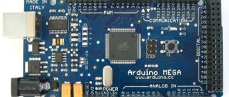
- >ESP8266 pinout
There are a huge number of varieties of the ESP8266 module. The figure shows some of them. The most popular option is ESP 01.
The execution of the program must be determined by the state of the GPIO0, GPIO2 and GPIO15 ports when the power supply ends. Two important modes can be distinguished - when the code is executed from the UART (GPIO0 = 0, GPIO2 = 1 and GPIO15 = 0) for flashing a flash card and when it is executed from an external ROM (GPIO0 = 1, GPIO2 = 1 and GPIO15 = 0) in the standard mode.
The pinout for ESP01 is shown in the picture.
- 1 – ground, 8 – power. According to the documentation, the voltage is supplied up to 3.6 V - this is important to take into account when working with Arduino, which is usually supplied with 5 V.
- 6 – RST, needed to reboot the microcontroller when a low logic level is applied to it.
- 4 – CP_PD, also used to put the device into energy saving mode.
- 7 and 0 – RXD0 and TXD0, this is a hardware UART required for flashing the module.
- 2 – TXD0, an LED is connected to this pin, which lights up when the logic level on GPIO1 is low and when data is transmitted via UART.
- 5 – GPIO0, input and output port, also allows you to put the device into programming mode (when the port is connected to a low logic level and voltage is applied).
- 3 – GPIO2, input and output port.
The main differences between Arduino and ESP8266
- The ESP8266 has a larger amount of flash memory, while the ESP8266 does not have non-volatile memory;
- ESP8266 processor is faster than Arduino;
- ESP8266 has Wi-Fi;
- ESP8266 consumes more current than Arduino;
Description of ESP8266
ESP8266 is a microcontroller with a WiFi interface that has the ability to execute programs from flash memory. The device was released in 2014 by the Chinese company Espressif and almost immediately became popular.
The controller is inexpensive, has a small number of external elements and has the following technical parameters:
- Supports Wi-Fi protocols 802.11 b/g/n with WEP, WPA, WPA2;
- Has 14 input and output ports, SPI, I2C, UART, 10-bit ADC;
- Supports external memory up to 16 MB;
- Required power supply is from 2.2 to 3.6 V, current consumption is up to 300 mA, depending on the selected mode.
An important feature is the absence of user non-volatile memory on the chip. The program is executed from an external SPI ROM using dynamic loading of the necessary program elements. Access to the internal peripherals can be obtained not from the documentation, but from the API of a set of libraries. The manufacturer indicates the approximate amount of RAM - 50 kB.
Features of the ESP8266 board:
- Convenient connection to a computer - via a USB cable, powered by it;
- Availability of built-in 3.3V voltage converter;
- Availability of 4 MB flash memory;
- Built-in buttons for rebooting and flashing;
- All ports are routed onto the board using two combs with a pitch of 2.5 mm.
Areas of application of the ESP8266 module
- Automation;
- Various systems for a smart home: Wireless control, wireless sockets, temperature control, addition to alarm systems;
- Mobile electronics;
- >ESP8266 pinout
There are a huge number of varieties of the ESP8266 module. The figure shows some of them. The most popular option is ESP 01.
The execution of the program must be determined by the state of the GPIO0, GPIO2 and GPIO15 ports when the power supply ends. Two important modes can be distinguished - when the code is executed from the UART (GPIO0 = 0, GPIO2 = 1 and GPIO15 = 0) for flashing a flash card and when it is executed from an external ROM (GPIO0 = 1, GPIO2 = 1 and GPIO15 = 0) in the standard mode.
The pinout for ESP01 is shown in the picture.
- 1 – ground, 8 – power. According to the documentation, the voltage is supplied up to 3.6 V - this is important to take into account when working with Arduino, which is usually supplied with 5 V.
- 6 – RST, needed to reboot the microcontroller when a low logic level is applied to it.
- 4 – CP_PD, also used to put the device into energy saving mode.
- 7 and 0 – RXD0 and TXD0, this is a hardware UART required for flashing the module.
- 2 – TXD0, an LED is connected to this pin, which lights up when the logic level on GPIO1 is low and when data is transmitted via UART.
- 5 – GPIO0, input and output port, also allows you to put the device into programming mode (when the port is connected to a low logic level and voltage is applied).
- 3 – GPIO2, input and output port.