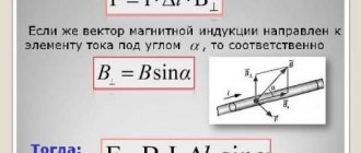
Positive and negative characteristics
In comparison with overhead lines, cable lines have their own positive distinctive characteristics, expressed as follows:
- Electrical networks in the form of cable lines have more compact forms, and their operation does not harm the surrounding landscape environment, which can be rationally used for other purposes.
- The flow of electricity is more reliably protected from all kinds of damage by third-party influences, since it is laid underground. In this case, overhead lines are subject to significant influence of climatic and other external factors. For example, icing, gusts of wind, falling branches, snowfalls and others.
- According to the technical characteristics of cable lines, their electromagnetic radiation is much lower than that of overhead lines, as a result of which the surrounding nature and human activity are minimally affected.
- The costs for ongoing maintenance and servicing of lines are significantly lower.
Negative characteristics include:
- Laying cables is much more expensive compared to overhead power lines, and the higher the voltage, the higher the cost. For example, installation of a line with an electrical voltage of 110 kV will cost almost 5 times more than a similar overhead line, and the cost of a cable line (compared to overhead) at a voltage of 500 kV will increase almost 20 times.
- If a line is damaged, the location of the damage is more difficult to detect, since the cables are hidden in the ground, and you will have to use certain methods to find damage to cable networks. It will take some time to determine it.
- Carrying out repair work is labor-intensive and repairs require significant investments in purchasing the necessary materials.
- If it takes about 6 hours to repair damage to an overhead line with a voltage of 110 kV, then you will have to tinker with the cable line for almost 72 hours, no less.
- Given the same cross-section of both lines, the first one will have a lower throughput, since the second line has better cooling conditions.
Read here! Electrical network design
Tubes instead of corners.
0
We asked representatives of Rosseti PJSC about what kind of alternative is replacing traditional ferrous metal supports. “In our company, which is the largest power grid operator in Russia,” says a specialist from this organization, “we have long tried to find a solution to the problems associated with lattice supports, and in the late 1990s we began to switch to faceted supports. These are cylindrical racks made of a bent profile, actually pipes, in cross section having the shape of a polyhedron. In addition, we began to use new methods of anti-corrosion protection, mainly the hot-dip galvanizing method. This is an electrochemical method of applying a protective coating to metal. In an aggressive environment, the zinc layer becomes thinner, but the load-bearing part of the support remains unharmed.”
0
In addition to greater durability, the new supports are also easier to install. There is no need to screw together any more corners: the tubular elements of the future support are simply inserted into each other, then the connection is secured. You can assemble such a structure eight to ten times faster than assembling a lattice structure. The foundations also underwent corresponding transformations. Instead of conventional concrete, they began to use so-called shell piles. The structure is lowered into the ground, a counter flange is attached to it, and the support itself is placed on it. The estimated service life of such supports is up to 70 years, that is, approximately twice as long as that of lattice supports.
Purpose and use
If laying overhead lines is impossible for technical reasons or they spoil the aesthetic appearance of the landscape, it is worth resorting to laying cable lines.
They are mainly used:
- inside residential buildings or industrial structures as power supply networks,
- in small cities or towns as an electrical network, where the voltage indicator will be no more than 20 kV, in regional centers and capitals for electrical networks of 110 kV.
- in industrial workshops, factory premises, on the territory of which administrative and other buildings for production purposes are located.
- in parks, gardens and city squares.
Differences in definitions
The device through which the flow of electrical energy or electrical impulses is transmitted is called a cable line. It consists, as a rule, of cables, the number of which can be different (from one or more), running in parallel, complete with various couplings (connecting, locking and end) and fixed using the fastening parts provided in the photo of the cable lines.
In addition, oil-containing lines are equipped with the necessary devices that monitor oil pressure and alarms.
Small spaces within which cables and couplings, oil-feeding devices and other devices that maintain the operation of cable lines in standard operating condition are mounted are called cable structures.
These include: tunnels and channels, boxes and blocks, mine shafts and double floors, and others. Almost all methods of laying cable lines require the presence of such structures for these purposes.
Manufactured in accordance with the current standard, the power electrical cable is used in cases of transmitting electricity using industrial frequency currents. They contain from one to several cores, separately insulated, coated and reliably protected from external influences; the method of protective coating depends on the operating conditions and laying.
Labeling rules
According to the established requirements for cable lines, marking is one of the main conditions of the current rules, i.e. each must be assigned a separate number or designation (name). When combining several cables in one power line, each individual cable is necessarily assigned its own personal number with a letter indicator: A, B, C, etc.
Cables laid in an open way and having couplings at the ends are equipped with tags with a special mark, voltage value, diameter size, own number and line name; tags on couplings fixed at the joints contain information about the number of the coupling itself and the date of installation.
Tags are generally placed along the entire length in increments of 50 m. For their production, materials resistant to natural conditions are used.
The shape of the tags may vary depending on the purpose of the cables. So, for high voltage power cables, with voltage not exceeding 1 kV and control cables, the shape will be round, rectangular and triangular, respectively.
You can learn in detail about how to lay cable lines on specialized websites using photos and video materials.
How to distinguish overhead power lines (VL)
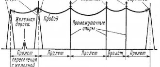
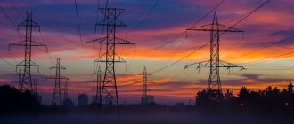
Do you like to travel by train, bus or car? If so, you are probably accompanied most of the way by various overhead lines consisting of cables or wires and supports. Communication lines give the road a special romance because people separated by a huge distance communicate through them using electrical signals. You can also find telegraph poles transmitting telegrams, “dying out” due to cellular communications and the Internet. However, above all these lines are power transmission lines that transfer electrical energy from its source to its consumers.
Typically, overhead power lines (EPLs) are easily distinguished from communication lines due to their enormous size. For example, the line "Itat - Barnaul - Ekibastuz - Kokshetau - Kostanay - Chelyabinsk", built in the 1980s, has a length of 2350 km and an average height of supports of 45 meters. The distance between the wires of adjacent phases on the Ekibastuz-Kokchetau section, designed for a record voltage of 1150 kV, is more than 8 meters. Above is a photo of this line.
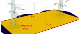
What causes such a greater distance between the wires? Is it possible to make it smaller? To answer these questions, you need to learn about the electrical strength and breakdown voltage of the air that actually makes up the insulation of power lines. When the electric field strength is 30,000,000 volts per 1 meter, a breakdown of the air gap occurs - an electric discharge in the air. The distance between the wires is regulated in the PUE and SNiP and is taken taking into account the dancing and vibration of the wires and adverse weather conditions. The wires can be self-supporting insulated - self-supporting insulated wires, which do not require insulators (used in networks up to 35 kV), or aluminum or steel-aluminum with a cross-section of up to 240 mm2. Copper wires are not used due to their high mass.
Similarly, the length and number of insulators separating overhead line (OHL) wires from grounded supports, which can be made of metal, reinforced concrete or wood, are determined by the electrical strength of the insulators. Electrical porcelain and low-alkali tempered glass are used as materials for insulators. The design of overhead power lines of different voltages is determined, in addition to the characteristics of the air, by the electrical strength and breakdown voltage of the insulators - up to 200 kV per insulator. Knowing this, you can understand how to determine the overhead line voltage by appearance and more. For example, walking with a child in the Friendship of Peoples Park in Minsk, it will not be difficult to answer him when he asks: “Dad, how many volts are in the power lines?”
Let's start in order. The minimum overhead line voltage is 0.4 kV. The supports of such a line are small and can resemble telegraph poles. Can also be used as lamp posts. Their crossarms usually have 5 wires, which are attached to small glass or porcelain insulators slightly larger than baby food jars.
Photo 1. Overhead line 0.4 kV
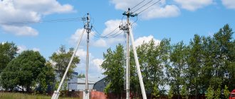
Transformers in villages and villages are powered by overhead lines with a voltage of 6-10 kV. The supports of these lines are higher, 8 meters or more, there are three wires. The insulators (one or two) are the size of a half-liter jar. 6-10 kV networks are predominantly made with an insulated neutral.
Photo 2. 6-10 kV power line
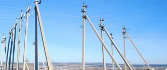
Power lines with a voltage of 35 kV, therefore, have even larger dimensions. The height of the supports is about 17 meters; garlands of three insulators are used on these lines. Glass insulators are good because when they break down, they are easy to notice, and maintenance and diagnostics of such overhead power lines are relatively easy.
Photo 3. 35 kV power line
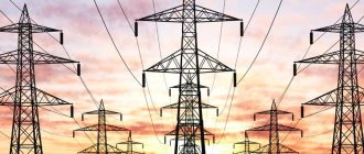
The next series of voltages is 110, 220, 330, 500 kV. The supports are 35-45 meters high. A characteristic crackling sound is heard from the wires, which occurs due to a corona discharge. A glow caused by discharges can be seen around the wires of 330 kV lines at night. Garlands contain a minimum of 6, 10, 14, 20 insulators. The number of wires in one phase is 1, 1, 2, 3, respectively. 750 kV power lines differ from 500 kV power lines in the number of wires in a phase - 4 or more instead of three.
Photo 4. Power lines 110, 220, 330, 500, 750 kV
And in conclusion, I would like to add that our company is not currently involved in installation, but carries out measurements and tests, including VL 0.4.
- Facebook()
www.38i.ru
Social buttons for Joomla