Device
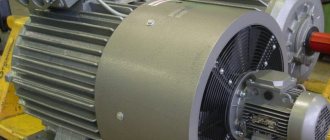
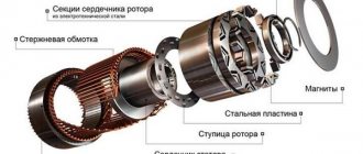
Structurally, a synchronous electric motor consists of a fixed element, a moving part, windings for various purposes, and can be equipped with a commutator unit. Next, we will consider each component of a synchronous unit in more detail using a working example (Figure 1).
Rice. 1. Design of a synchronous electric motor
- Stator or armature - made of electrical steel, monolithic or assembled from laminated iron. Designed to accommodate the working winding, it conducts power lines of the electromagnetic field formed by flowing currents.
- The winding on the stator is made of copper conductors; depending on the type of stator of the synchronous electric motor, it can be made using various methods, methods of winding and arrangement of conductors. It is used to supply power voltage and generate a working magnetic flux.
- Rotor with field winding - designed to interact with the magnetic field of the stator. As a result of applying voltage to the excitation winding, its own magnetic field is created in the electric motor rotor, which sets the state of the rotating element.
- Shaft - used to transmit rotational force from the electric motor to the load connected to it. In most cases, this is the base on which the charge or rotor poles, bearings, rings, plates and other auxiliary elements are mounted.
- Slip rings are used to supply power to the rotor windings, but are not installed in all models of synchronous units. Power is supplied through a special AC-DC voltage converter.
- Housing - designed to protect against external factors, provides the synchronous motor with sufficient strength and tightness, depending on its operating conditions.
Regarding overload capabilities
It all depends on the excitation currents. If you increase the overload capacity and operating principle of the engine and at the same time reduce the power of electricity, then this can be done by increasing the excitation power to the exciter. When automatically changing the power supply, a voltage relay is involved, and its coil is connected to the motor power supply via electricity transformers and intermediate relays. If the power supply is normal, then the coil is open. When the strength of electricity decreases, the contacts close and power is supplied to the coil.
Increasing the overload capacity of mechanisms
You can also increase the overload capacity of the motor when the electricity in the network decreases by increasing the excitation power. You can automatically change the excitation power through a power relay, but its coil must be connected to the power supply networks of the mechanism via a transformer for electricity, as well as intermediate relays. If there is normal electricity in the network, then the contacts in the circuits are open. And when it decreases, they close and power is supplied to the coil, then the relays will be shunted by their rheostat contacts in the exciter circuits.
Overload capacity of synchronous motor
Thanks to the excitation boost, it will be possible to increase the overload capacity of the motors for a short time, thereby obtaining additional reactive power. After increasing the stator power during boost, the stability of the equipment at reduced power will increase, and the reactive power it produces will increase, so this will have a good effect on the operating mode of the consumer in these load nodes.
Once the expression for the maximum torque becomes clear, it becomes clear that the final overload capabilities of the units are proportional to the first power of the voltage. This differs from asynchronous engines - because with them it is proportional to the square of the power supply. It can be concluded that synchronous models of mechanisms are not as sensitive to voltage changes.
Conclusion:
By means of the reactive torque, it is possible to increase the steepness of the angular characteristic in the working section and, in some way, increase the overload capacity of the motor. It turns out that the overload capabilities of synchronous models will not be as sensitive to a decrease in power supply in the network than that of asynchronous units. It is very important!
Principle of operation
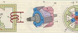
The operation of a synchronous electric motor is based on the interaction of the magnetic flux generated by the working windings with a constant magnetic flux. The most common model of a synchronous electric machine is the version with a working winding on the stator and an excitation winding on the rotor.
Rice. 2. Operating principle of a synchronous electric motor
As you can see in Figure 2 above, three-phase voltage from the network is supplied to the stator winding, which forms an alternating magnetic field. A constant voltage is applied to the rotor windings of the electric motor, which induces the same constant magnetic flux at the poles. For clarity, let’s consider the process using a simplified model of a synchronous unit (Figure 3).
Rice. 3. The principle of flow formation in a synchronous electric machine
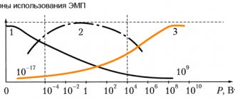
When power is supplied to the phase turns of the stator of the electric motor, the first peak of the current amplitude and mutual inductance EMF occurs in phase A, then B and phase C.
The graph shows the frequency of alternation of curves depending on time:
- at point 1, the maximum EMF EA forms the maximum flux, and the electromotive forces of the EB and EC phases are equal to each other and opposite in sign, they complement the resulting force.
- at point 2, the EMF EB reaches its peak, and the electromotive forces of the EA and EC phases become equal to each other and opposite in sign, they complement the resulting force, as a result of which the magnetic field performs a rotational motion.
- at point 3, the maximum falls on the emf EC, and the electromotive forces of the EB and EA phases together complement the resulting force and again shift the field vector clockwise.
The rotation of the stator field occurs over a period, and due to the fact that the rotor has its own electromagnetic force that is constant over time, it synchronously follows the movement of the alternating magnetic field, rotating around a given axis. As a result of such rotation, synchronous movement of the rotor occurs following a change in the amplitude of the EMF in the turns of the working windings; due to this phenomenon, the electric motor is called synchronous. The presence of a separate power supply was also reflected in the schematic designation of such electrical machines (Figure 4) in accordance with GOST 2.722-68.
Rice. 4. Schematic designation of a synchronous electric motor
Electric cars
Ministry of Education and Science of the Russian Federation
Omsk State Technical University
Department of “Theoretical and General Electrical Engineering”
Electric cars
LECTURE: “Magnetic field and basic parameters of synchronous machines. Idling of the synchronous generator. Anchor reaction. Two reaction method. Electromagnetic parameters in relative units. ”
Omsk 2005
1. Basic terms and definitions (GOST “Rotating electric machines”).
1. Idle speed characteristics of an electric machine generator (x idle speed characteristics)
— dependence of the electromotive force of the armature winding of a rotating electric machine generator on the excitation current with the armature winding open and at a given rotation speed
2. Normal idle characteristics of an electric machine generator ( normal idle characteristics)
- averaged idle characteristics of an electric machine generator, expressed in relative units
3. Magnetic induction in the working gap of a rotating electric machine - a
amplitude of the fundamental harmonic in the distribution curve of magnetic induction in the working gap in idle mode at the rated voltage of a rotating electrical machine
4. Reaction of the armature of a rotating electric machine -
the effect of the magnetomotive force of the armature winding on the magnetic field of a rotating electrical machine created by the field winding or permanent magnets
5. Longitudinal reaction of the armature of a rotating electric machine (longitudinal reaction of the armature)
- reaction of the armature of a rotating electrical machine, formed by the component of the magnetizing force of the armature winding, creating a magnetic flux directed along the longitudinal axis of the poles
6. Transverse reaction of the armature of a rotating electric machine (transverse reaction of the armature)
- the reaction of a rotating electrical machine, formed by the component of the magnetizing force of the armature winding, creating a magnetic flux directed along the transverse axis of the poles
7. Component of the magnetizing force of the winding along the longitudinal axis of a synchronous machine (component of the magnetizing force along the longitudinal axis)
- component of the magnetizing force of the winding, directed along the axis of the poles of the inductor of the synchronous machine
8. Component of the magnetizing force of the winding along the transverse axis of the synchronous machine (
component of the magnetizing force along the transverse axis) - the component of the magnetizing force of the winding, which is directed perpendicular to the axis of the poles of the inductor of a synchronous machine
9.Winding current component along the longitudinal axis of a synchronous machine
(current component along the longitudinal axis) - a component of the winding current that creates a component of the magnetizing force of the winding directed along the longitudinal axis of the synchronous machine
10. Winding current component along the transverse axis of a synchronous machine
(current component along the transverse axis) - a component of the winding current that creates a component of the magnetizing force of the winding directed along the transverse axis of the poles of the inductor of a synchronous machine
2. Idling of synchronous generators
Idling of an autonomous synchronous generator means an operating mode when the rotor is rotated by the drive motor and the current in the open armature winding is zero. In this case, the magnetic field of the machine will be created only by the current of the field winding. This field can be decomposed into two components: the main field, the magnetic lines of which pass through the air gap and mesh with the armature winding, and the stray field of the poles, the magnetic lines of which only mesh with the field winding.
The magnetic flux of the main field when the rotor rotates induces an emf in the armature winding. The EMF induced in the armature winding of a synchronous generator and the voltage at its terminals are required to be close to sinusoidal in shape. This is due to the fact that with sinusoidal EMF and voltage, the current in the armature and in the load, with the linear nature of the magnetic circuit and load, will also be sinusoidal. As a result, the total losses in the generator and consumers are reduced, since there will be no additional losses from higher harmonics. Checking the sinusoidality of the curve is performed for the linear voltage with the working circuit of the armature winding connection. The criterion for evaluation is the distortion coefficient of the sinusoidal curve, expressed as a percentage:
where Em
,
Emv
is the amplitude (or effective) value of the fundamental and highest harmonic component of the EMF.
The standard requires that the distortion coefficient of the line voltage curve in three-phase alternating current generators with a frequency of 50 Hz be no more than 5% for generators with a power of over 100 kV∙A and no more than 10% for generators with a power of up to 100 kV∙A.
Rice. 1. A pole of a salient-pole synchronous generator with an unequal air gap (a) and the distribution of magnetic induction in the gap (b)
→
Rice. 2. Pole division of a non-salient-pole synchronous generator (a) and excitation MMF distribution curve (b)
To obtain an EMF curve close to a sinusoid, it is first necessary that the excitation field curve of the machine be as close to a sinusoid as possible. In a salient-pole machine, for this purpose, the gap between the pole and the stator is made unequal (Fig. 1, a). Usually, the gap under the edges of the pole is taken to be 1.5-2 times larger than under the middle. Induction distribution
under the pole with this configuration of its tip is shown in Fig. 1, b. There, the dashed line for comparison shows the induction curve with a uniform gap.
In a non-salient pole machine, improving the shape of the excitation field is achieved by choosing the ratio between the wound and unwound parts of the pole division (Fig. 2, a). Neglecting the influence of the grooves, which create some steps in the MMF and induction curve, we can assume that the excitation MMF, as well as the field curve, are distributed around the circumference of a cylindrical rotor with implicit poles according to the trapezoidal law. Then the amplitudes of the main harmonics of the MMF and field induction will be respectively equal:
where FB 1
and
Bσ1
are the maximum values of the 1st harmonic MMF of the excitation winding per one pole and
induction in the gap ;
wB
,
I
B - turns of the field winding per pole and field current.
In order to improve the excitation field curve, the unwound part is chosen equal to τ/3 (α=π/3). In this case (in the field curve, all harmonics with a number divisible by 3 will be absent, and the remaining higher harmonics will be weakened. In addition, to improve the shape of the induced EMF curve, distribute the armature winding over the slots and shorten its pitch. In large multi-pole machines, the curve can be improved EMF is promoted by the use of windings with fractional q
.
An important characteristic of a synchronous machine is the idle speed characteristic
.
It represents the dependence of the EMF induced in the armature winding E on the current in the field winding I
B at a constant rotor speed. This characteristic allows you to evaluate the saturation of the magnetic circuit of the machine; in addition, it is used to construct vector diagrams and other characteristics of the machine.
By calculation, the idle speed characteristic can be obtained from the calculation of the magnetic circuit.
In Fig. Figure 3 shows a diagram for taking the idle speed characteristics experimentally. Using resistor R
B the excitation current is changed from the maximum value to zero, while recording the readings of the ammeter and voltmeter.
The experimental idle speed characteristic is shown in Fig. 4 dashed line. At I
B= 0, the EMF is equal to the EMF from residual magnetism
EOCT
=2÷3%
UHOM
. In calculations, the idle speed characteristic is usually used, which is obtained by shifting the experimental characteristic to the right by segment A0 (solid line).
Based on a comparison of the no-load characteristics of various synchronous generators, it was found that these characteristics differ little from each other if they are constructed in relative units. When converting EMF into relative units, its current value in volts is divided by the rated armature voltage ( E*= E / UHOM
).
The relative value of the excitation current is found by the ratio of the current value of the excitation current in amperes to the current taken as the base I
B,b.
The base excitation current I
B,b is taken to be the current corresponding to the no-load characteristic
E = U NOM.
| Rice. 3. Scheme for removal - idle characteristics | Rice. 4. Idle characteristics |
The characteristics obtained in this way are called normal idle characteristics. These characteristics for salient-pole and non-salient-pole generators are given in the table.
| I B | 0 | 0,5 | 1 | 1,5 | 2 | 2,5 | 3 | 3,5 |
| E * |
Note. The numerator of the fraction contains the EMF of salient-pole generators (hydrogen generators), and the denominator contains the emf of non-salient-pole generators (turbine generators).
3. Anchor reaction
If a single three-phase synchronous generator is connected to a symmetrical load, then equal currents will flow through the armature winding phases, but shifted relative to each other by an electrical angle of 120°. These currents will create a rotating magnetic field. The armature field moves in space with the same rotation frequency and in the same direction as the excitation field, i.e., these fields will be stationary in relation to each other. The resulting field of the machine under load will be created by the combined action of the MMF of the field winding and the MMF of the armature winding. It will be different from the field at idle.
The effect of the MMF of the armature on the machine field is called the armature reaction. The nature of this effect depends on the relative location in space of the excitation and anchor fields. The excitation field is always directed along the axis of the poles and causes the EMF in the conductors of the armature winding. It is customary to call the axis coinciding with the axis of the poles the longitudinal axis of the machine, and the axis perpendicular to it - the transverse axis. The orientation of the armature field in space depends on the distribution of current in the conductors of its winding, which in turn is determined by the shift angle of this current from the induced EMF. In what follows, we will denote this shift angle by the letter ψ. The angle ψ varies from π/2 to -π/2 and depends on the nature of the generator load. Let us consider from the qualitative side the manifestation of the anchor reaction in three extreme cases.
The currents in the phases lag behind the corresponding EMF by an angle ψ=π/2. If we neglect the relatively small active resistance of the armature phase, then we can assume that this angle corresponds to the inductive nature of the load.
In Fig. Figure 5 shows a cross section of a two-pole synchronous generator. To simplify, the winding of each phase is represented by a single-turn coil with a diametric pitch. We will assume that the magnetic field of the poles has a sinusoidal character. When the rotor rotates, an EMF is induced in the windings of the armature phases, the direction of which is determined by the right-hand rule. For the moment of time shown in Fig. 6, the direction of these EMFs is shown by the icons: a cross and a dot outside the conductor. The maximum EMF will be induced in the conductors of phase A, located under the middle of the poles, where the induction has its maximum value.
| Rice. 5. Armature reaction with a purely inductive load ( FB — excitation flow; | Rice. 6. Vector diagram of a synchronous generator for the moment in time shown in Fig. 5 |
To simplify, the winding of each phase is represented by a single-turn coil with a diametric pitch. We will assume that the magnetic field of the poles has a sinusoidal character. When the rotor rotates, an EMF is induced in the windings of the armature phases, the direction of which is determined by the right-hand rule. For the moment of time shown in Fig. 5, the direction of these EMFs is shown by the icons: a cross and a dot outside the conductor. The maximum EMF will be induced in the conductors of phase A, located under the middle of the poles, where the induction has its maximum value.
In Fig. Figure 6 shows a vector diagram of EMF and currents. The magnitude and direction of the instantaneous values of currents in the phases and their direction are determined by designing current vectors I A
,
I B
,
I C
to the vertical axis. Based on this, in Fig. Figure 5 inside the conductors shows the direction of currents in the phases. As follows from Fig. 5 and 6, the current in phase A at the considered moment of time is zero, and in phases B and C the currents are equal, but opposite in direction. These currents create a magnetic field, the direction of which, determined by the gimlet rule, is shown in Fig. 5. In relation to the axis of the poles, it is longitudinal and directed towards the excitation field. Thus, with an inductive load in a synchronous generator, a longitudinal demagnetizing reaction of the armature occurs, as a result of which the resulting flux and the EMF induced in the armature winding will be less than during no-load.
If, using the left-hand rule according to Fig. 5, determine the direction of forces f
, acting on the armature conductors, then it can be established that the conductors located under the same pole are acted upon by forces directed in opposite directions, and the resulting electromagnetic moment of the machine will be equal to zero. Thus, during the longitudinal reaction of the armature, no electromagnetic torque is created in the synchronous generator.
Capacitive load. The phase currents advance the corresponding EMF by an angle ψ=-π/2. On,Fig. Figure 7 shows a cross-section of a synchronous generator corresponding to the same point in time as in Fig. 5. According to the vector diagram (fig. shows the direction of currents in the conductors of the armature winding. In the case under consideration, the distribution of current along the armature conductors remains the same as with an inductive load, but changes to the opposite direction of the current in phases B
and
S.
_ In accordance with this, the field of the armature is relative to the axis of the poles! will also be longitudinal, but it will have a magnetizing effect on the excitation field. Consequently, with a capacitive load, the armature reaction in a synchronous generator will be longitudinal and magnetizing.
By analogy with the previous case, it can be shown that with a capacitive load no electromagnetic torque is created.
| Rice. 7. Armature reaction with purely capacitive load | Rice. 8. Vector diagram of a synchronous generator for the moment in time shown in Fig. 7 |
Load corresponding to ψ=0. In this case, the phase currents will coincide with the EMF induced in them. To do this, the synchronous generator must be loaded not on an active load, but on an active-capacitive load. Capacitance x C NG
must be selected so that it compensates for the inductive reactance of the armature winding phase.
A cross-section of the machine and a vector diagram for the case under consideration are shown in Fig. 9, 10. The maximum current will be in phase A, where at the moment the EMF is also maximum. In phases B and C, the currents are 2 times less than in phase A, and are oppositely directed to the current in phase A. The magnetic field created by the armature currents, in relation to the pole axis, is transverse. It will weaken the field on the advancing half of the pole and strengthen it on the escaping half of the pole.
The transverse field of the armature does not change the flow if the machine is unsaturated, and will slightly reduce it in a saturated machine. Thus, under load, when ψ = 0, a transverse armature reaction occurs, distorting the magnetic field in the machine gap. For this case, the electromagnetic forces created by the current flowing through the conductors of the stator winding are directed in the same direction, coinciding with the direction of rotation of the rotor.
Rice. 9. Armature reaction at ψ=0
→
Rice. 10. Vector diagram of a synchronous generator for the moment in time shown in Fig. 9
Rice. 11. Decomposition of current I
into longitudinal
I
d and transverse
Iq
components
Since these conductors, together with the stator, are stationary, a reaction to the rotor occurs, directed in the direction opposite to its rotation. Thus, at ψ=0, electromagnetic forces in the generator will create a braking torque acting on the rotor.
In general, when 0<|ψ|<90°, current I
can be decomposed into two components (Fig. 11).
One of these components I
q is in phase with the emf, creates a transverse armature reaction and is called
transverse armature current
.
Another component of I
α.
perpendicular to the emf, creates a longitudinal reaction of the armature and is called longitudinal armature current
. Thus, in the general case, both longitudinal and transverse armature reactions will exist in a machine under load.
4. Features of the armature reaction in a salient-pole generator. Two reaction method
The armature magnetic flux is proportional to the MMF of the armature winding F
a and is inversely proportional to the magnetic resistance Rμ of the circuit through which this flow is closed.
The main part of the magnetic resistance is made up of air gaps σ between the stator and rotor. In a non-salient-pole generator, it can be assumed that along the entire pole division of the machine σ=const, and therefore Rμ=const. Therefore, in these generators, the armature flux and the emf E
a induced by it are a function of the MMF
F
a and do not depend on the position of the axis of this MMF relative to the poles.
In a salient-pole synchronous machine, the rotor is magnetically asymmetrical (the air gap along its longitudinal axis is smaller than along the transverse one). As a result, when the nature of the load and the angle ψ change, the magnetic resistance for the armature flux will change. Therefore, in a salient-pole generator, the magnetic flux created by the armature and its shape depend on two quantities - MMF F
a and angle ψ. This causes difficulties in taking into account the influence of the armature field on the excitation field.
Rice. 12. Expansion of the MMF of the armature F
and into two components:
F
d and
F
q
To facilitate taking into account the armature reaction in a salient-pole machine, the method of two reactions, proposed in 1895 by the French electrical engineer A. Blondel, is widely used.
According to this method, the 1st harmonic of the MMF of the armature reaction F
a is decomposed into two components:
In Fig. 12 for a two-pole machine shows the vectors of MMF F
α and the components of this MMF
F
d and
F
q.
The spatial vector of the MMF F
α in the figure is oriented in accordance with the distribution of current
i
in the conductors of the stator winding (outer circle).
It is assumed that the current lags behind the induced emf by an angle ψ. The direction of the emf e is
determined by the right-hand rule and is shown on the inner circle in Fig. 12.
Component F
d coincides with the axis of the poles and is
the longitudinal component of the armature reaction
.
F
component is directed perpendicular to the pole axis and is
the transverse armature reaction .
It can be assumed that the first component is created by the current
I
d, and the second by the current
I
q (see Fig. 11). The first harmonics of the MMF components of the armature reaction will be equal to:
Along the axis of each component of the armature reaction, the air gaps between the stator and the rotor are unchanged, therefore the fluxes created by these components will depend only on the corresponding MMF. The distribution of the field curve for each component of the armature reaction retains its shape for any value of the angle ψ and will depend on the gap and configuration of the pole piece.
When calculating and constructing vector diagrams for synchronous salient-pole machines, it is necessary to determine the resulting MMF under load from the combined action of the field and armature windings. But these windings have different spatial distributions, and therefore the same MMF of these windings will create different 1st harmonic fluxes in the machine gap. The distributed armature winding creates sinusoidal MMF Fd and Fq, and the concentrated excitation winding forms a rectangular MMF FB. Therefore, in order to determine the resulting MDS, it is necessary to reduce one MDS to another. Since usually when calculating and constructing diagrams, the idle characteristic is used E = f ( FB )
, then it is advisable to bring the MMF of the armature to the excitation winding.
In order to find the excitation windings Fad and Faq equivalent in action to the MMF Fd and Fq, it is necessary to multiply the former by the coefficients kd
.
and kq
:
Thus, the MMF of the field winding Fad
and
Faq
will create such a distribution of fields, the 1st harmonics of which will induce the same EMF in the armature winding as the 1st harmonics of the fields created by the MMF
Fd
and
Fq
(respectively).
5. Electromagnetic parameters in relative units
In the theory of steady-state, and especially transient, processes of a synchronous machine, relative units are widely used. In this case, their nominal phase values are taken as the basic values of current, voltage, resistance and inductance of the armature circuit:
; . (1)
Relative values of resistances r, x,
z
and inductance
L
of the armature circuit:
; ; ; . (2)
Relative values of inductance L *
and the corresponding inductive reactance
x*
are thus equal.
RMS current values I
and armature voltage
U
in relative units:
; . (3)
The relative magnitude of the excitation current is discussed above when constructing the normal idle characteristics.
6. Basic provisions
1. To improve the sinusoidal distribution of the magnetic field in the air gap of a synchronous machine:
- in a salient-pole machine, the gap between the pole and the stator is unequal;
— in a non-salient-pole machine, this is achieved by choosing the ratio between the wound and unwound parts of the pole division (the winding usually occupies 2/3 of the pole division).
2. Normal idle characteristics:
| I B | 0 | 0,5 | 1 | 1,5 | 2 | 2,5 | 3 | 3,5 |
| E * |
(in the numerator of the fraction the EMF of salient-pole generators (hydrogen generators) is given, and in the denominator - of non-salient-pole generators (turbine generators)).
3. The effect of the MMF of the armature on the machine field is called the armature reaction
.
4. Armature current I
and the magnetizing force created by it is divided into two components:
This is called the two reaction method.
5. The nominal phase values are taken as the basic values of current, voltage, resistance and inductance of the armature circuit, when presented in relative units.
7.
Test questions and homework
| № | Content | Literature |
| 1 | What process occurring in a synchronous generator is called idle running? | 2, § 4-4 |
| 2 | What is the criterion for assessing the sinusoidality of the EMF curve induced in the armature winding of a synchronous generator (indicate the calculation formula) | 2, § 4-4 |
| 3 | Ways to improve the shape of the EMF curve in a salient-pole and non-salient-pole synchronous machine? | 2, § 4-4 |
| 4 | What is meant by the idle speed characteristics of an electric machine generator? | 2, § 4-4; 3, §33-2 |
| 5 | What is normal idle speed? | 2, § 4-4 |
| 6 | What is anchor reaction? | 3, §33-1 |
| 7 | How does the armature reaction of a synchronous generator change with a capacitive, active and inductive load? | 3, §32-2 |
| 8 | How do the magnetic fluxes of the armature reaction of a salient-pole and non-salient-pole synchronous machine depend on the MMF of the armature winding? | 3, §32-2 |
| 9 | What is the two reaction method? | 3, §32-2 |
| 10 | Determine the longitudinal and transverse components of the MMF of the armature of a three-phase synchronous generator at rated power Sn = 150 kVA; U1nom = 6.3 kV; cosψ = 0.8, if its four-pole stator winding with winding coefficient kw1 = 0.92 contains w1 = 312 series-connected turns in each phase, and the generator load is rated | 1, §33-1 |
8. Literature
1. Tokarev machines. – M.: Energoatomizdat, 1990, 624 p.
2. Kopylov machines - M.: Logos, 2000, 607 p.
3. Woldek machines. – L.: Energy, 1978. – 832 p.
Get text
Difference from an asynchronous motor
The main difference between a synchronous electric motor and an asynchronous one is the principle of converting electrical energy into mechanical rotation. In a synchronous electric motor, the rotor rotation process is identical to the rotation of the working electromagnetic field generated by a three-phase network. But in an asynchronous one, the working field independently induces an EMF in the rotor, which then generates its own flow of mutual induction and causes the shaft to rotate. As a result, asynchronous electric machines receive a difference in the rotation of the working field and the load on the shaft, which is expressed by a physical quantity - slip.
In operation are classic models of asynchronous electric motors with a squirrel-cage rotor:
- do not tolerate overloads well;
- have difficulty starting with significant force;
- change the rotation speed depending on the load of the working body.
To some extent, these shortcomings are overcome by an asynchronous motor with a wound rotor, but only a synchronous unit can completely get rid of these shortcomings.
Rice. 5. Difference between an asynchronous and a synchronous electric motor
The working process
A synchronous motor is an electrical device that operates on the basis of the law of electromagnetic induction. The operating principle and design of the LED are based on the practical application of this physical phenomenon. The magnetic field is created by a three-phase winding placed in the slots of the stator package, similar to the circuit of an asynchronous machine. The rotor contains an excitation winding powered by direct current. Power is supplied to it through brushes and rings. The direct current flowing through the exciting winding interacts with the rotating field of the inductor, which causes circular motion of the shaft. Torque depends on the current load and is independent of speed. That is why this type of drive is called a synchronous electric motor, that is, the speed of the armature is equal to the speed of the inductor field.
Once started, the AC synchronous motor rotates simultaneously with the magnetic flux. The SD cannot be started using only the mains supply. This is explained by the inertia of the rotor unit and the high speed of the rotating field. The switching circuit of a low-power machine involves the use of starting (damper) windings, with which it operates as a synchronous motor with a squirrel-cage rotor (that is, an asynchronous start is realized). In the case of powerful electric drives, the start is carried out by an auxiliary electric motor or frequency converter.
The most widespread is asynchronous starting, which involves the installation of an additional short-circuit winding. In this case, a synchronous motor with a squirrel-cage rotor is started similarly to an asynchronous electric motor. As a result of such actions, the rotor mechanism accelerates to the speed of the rotating magnetic flux. If a synchronous motor is loaded, the distance between the armature and field poles increases. As a result, the anchor mechanism lags behind the load angle, which corresponds to the lag from its position at idle.
The design and operating principle of a synchronous motor provide for operation of the drive at a constant speed, which does not depend on the load. The LED is not designed for a load whose value exceeds the starting power between the rotor mechanism and the magnetic flux. Otherwise, the synchronism is interrupted and the operation of the synchronous motor stops.
Varieties
In modern industry and household appliances, synchronous electric motors are used to solve a wide variety of problems. As a result, their design features also differ significantly. In practice, there are several criteria by which types of synchronous units are divided. In accordance with GOST 16264.2-85 they can be divided according to the following technical characteristics:
- supply voltage;
- operating voltage frequency;
- number of revolutions.
Depending on the method of obtaining the rotor field, the following types of synchronous electric motors are distinguished:
- With an excitation winding on the rotor - the synchronizing force is created by supplying power from the converter.
- With a magnetic rotor - a permanent magnet is installed on the shaft, performing the same functions as the field winding, but without the need for recharge (see Figure 6).
Rice.
6. Synchronous electric motor with permanent magnets With a reluctance rotor - the design is made in such a way that refraction of magnetic lines occurs in its core, causing the entire structure to move (see Figure 7). Under the influence of a force field, the transverse and longitudinal components in the rotor are not equal, due to which the plates rotate following the field.
Rice. 7. Example of a jet rotor
Depending on the presence of poles, all synchronous electric motors can be divided into:
- salient-pole - the design clearly shows separate poles with windings, used for low speeds;
- non-salient pole - the pole is not highlighted, such models are installed for high speeds;
Depending on the location of the working windings, a distinction is made between direct (on the stator) and reverse (working windings on the rotor).
Mechanical and angular characteristics
Due to the inherent features of a synchronous motor, the value of its torque does not depend on the rotation speed. This property of the drive determines its purpose and scope of application. The technical qualities of drive equipment for configuring an electric drive are assessed by the dependence of the motor speed on the electromagnetic torque developed by it. This relationship is known as the mechanical characteristic of a synchronous motor. It can be static or dynamic. The first shows the behavior of the LED in a stable operating mode. The second characterizes his work during the transition period.
The quality of mechanical characteristics is assessed by rigidity. With respect to this parameter, all characteristics are divided into ideally hard, hard and soft. Due to the fact that the rotor speed of a synchronous motor does not change under load, this type of electric motor has an ideally rigid characteristic, which is expressed by the formula:
n = 60*f1/p,
where f1
– stator current frequency;
p –
number of pole pairs of the stator winding.
But the dependence n = f (M)
does not reflect the full behavior of the motor, in which, as the load increases, the axes of the inductor and armature field shift. Each load corresponds to a certain angle between their axes. Angular characteristic equation:
Mem = Mmax*sin θ
This formula expresses the approximate dependence of the torque on the shaft on the rotor departure angle. In real conditions, the maximum torque corresponds to an angle slightly less than 90˚. In this case, the overload capacity of the SD is equal to: λm = Мmax/MN = 2–3.
Operating modes
Most electric machines have a reversible function, and synchronous units are no exception. They can also be used as an electric drive or as a generator to produce electricity. Both modes differ in the way they influence the electric machine - applying voltage to the working windings or driving the rotor due to mechanical force.
Generator mode
Synchronous generators are used to produce electricity into the network. In most cases, electric machines with phase windings on the stator are used for this purpose, which significantly simplifies the process of collecting power and its further transfer to the network. Physically, generation occurs when exposed to the electromagnetic field of the excitation winding of a synchronous generator with stator windings. The power lines alternately cross the phase turns and induce mutual induction emf in them, as a result of which voltage appears at the terminal terminals.
The frequency of the resulting voltage directly depends on the shaft rotation speed and is calculated by the formula:
f = (n*p)/60 ,
where n is the shaft rotation speed, measured in revolutions per minute, p is the number of pole pairs.
Synchronous compensator
Due to the physical characteristics of the synchronous electric motor, when the device is idling, it consumes reactive power from the network, which can significantly improve the cosφ of the system, practically bringing it closer to 1. In practice, the synchronous compensator mode is used both to improve the power factor and to stabilize the network voltage parameters.
Motor mode
In a synchronous machine, the motor mode is carried out when a three-phase operating voltage is supplied to the armature windings. After which the electromagnetic field of the armature begins to push the magnetic field of the rotor, and the shaft begins to rotate. However, in practice, the propulsion mode is not so simple, since powerful units cannot independently gain the necessary speed resource. Therefore, during startup, special methods and connection diagrams are used.
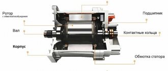
General operating principle
According to its basic design, the stator is considered the armature of the machine and has a multiphase winding, most often designed for three phases. It acts as an inductor, the rotor (excitation) winding serves to create a flux of excitation magnetic induction, it is powered using slip rings, through a brush mechanism, from a source (exciter armature). The design of the machine, first of all, depends on the required rotation speed, this mainly affects the design features of the rotor; there are two main types, these are salient-pole and non-salient-pole types.
Starting methods and connection diagrams
To start a synchronous electric motor, an additional field is required, independent of the network influence. At the same time, at the starting stage, the start-up is an asynchronous process until the unit reaches synchronous speed.
Rice. 8. Synchronous motor starting circuit
When voltage is applied to the armature, a current occurs in its windings and an EMF is generated in the rotor iron, which ensures asynchronous movement until the field windings are powered.
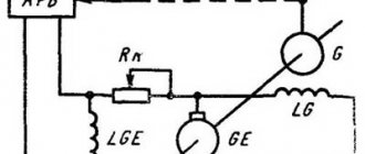
Another common starting option is the use of additional generators, which can be located on the shaft or installed separately. This method provides additional starting force due to external torque.
Rice. 9. Generator method of starting a synchronous motor
As you can see in Figure 9, the initial rotation of the motor M is carried out by the generator G, which is designed to bring the device to a subsynchronous speed. Then the generator is removed from the operating circuit by opening the KM contacts or automatically when the operating characteristics are set. Further maintenance of the synchronous mode occurs due to the supply of constant voltage to the excitation winding.
In addition, in practice a starting circuit with semiconductor converters is used. Figure 10 shows a thyristor converter method with the installation of rotating rectifiers.
Rice. 10. Thyristor circuit for starting a synchronous motor
In the first case, the start of a synchronous electric motor is characterized by zero voltage from the converter UD. Due to the sliding EMF through the zener diodes VD, the thyristors VS are opened. A resistor R is introduced into the excitation winding circuit, designed to prevent insulation breakdown. As the electric motor accelerates, the sliding EMF will decrease proportionally and the zener diodes VD will lock, the circuit will be blocked, and the excitation winding will receive constant voltage power through UD.
Advantages of synchronous models
They have no initial trigger points. How to depict this? When they are connected to an alternating voltage network with the electromagnet stationary, and a constant voltage passes through the winding, then during one period the electromagnetic moments will change, and with them the direction will change, because the average torque during the period will be equal to 0. During Under these conditions, the engine will not be able to rotate due to the rotor having a certain inertia. This is evidenced by research.
The most common launch methods:
- frequency - the unit and its power supply smoothly changes from 0 to the nominal value, and the electromagnets rotate synchronously with the magnetic fields of the stators;
- using auxiliary engines - the rotors of the excited motors are driven to a certain speed and connected to the network using synchronizing devices, then the engine is turned off (but it is impossible to start a mechanism that is under load, because it is wrong to use a starting unit with more power);
- asynchronous - the engine is started in an asynchronous way, and for this it is equipped with a specialized winding for starting, reminiscent of a squirrel cage (to increase the resistance of the rods, the cage is made of brass).
Synchronous motor starting schemes The
advantages of this type of motor include the presence of less sensitivity to energy fluctuations, because their maximum torques are proportional to the amount of energy to the first power. Regardless of the mechanical load on the shaft, the rotation speed is strictly constant and the efficiency increases.
Negative points:
- the design is complex;
- launching is also complicated;
- It is difficult to regulate the rotation speed because you can only change the frequency of the supply voltage.
If we take into account all the disadvantages of synchronous motors, then they are much less profitable than asynchronous ones, when the power is limited to 100 kW. But when the power is much higher and the dimensions of the car are smaller, the former are preferred to the latter.
Application
The scope of application of synchronous electrical machines covers the production of electrical energy at power plants. By type, generators are divided into turbine, diesel and hydraulic, depending on the method of driving them into rotation.
They are also used as electric motors, which can withstand significant overloads during operation. Such motors are installed on fans, compressors, power units and other equipment. A separate category of electric motors is used in precision equipment, where synchronization of operations and processes is important.
Methods for connecting three-phase electric motors to a 220 volt network
Some professionals use power tools for different purposes (technical issues) when working. Sometimes they are driven by 3-phase motors. Three-phase only is not always available in regular garages and homes. Then you can use the diagram for connecting a 3-phase motor to a single-phase network.
The most common and used in machine tools are 3-phase asynchronous alternating voltage mechanisms with a short-circuited stator. These are the ones that have to be connected. When the motor is turned on in a 3-phase network with 3 winding layers, alternating currents will flow at different intervals. They create a magnetic field that rotates and rotates the stator.
What to do when connecting units to single-phase networks
When the motor is connected to a single-phase network, power flows through the winding, only a rotating magnetic field is not formed and the rotor remains motionless. As an output, you can connect a capacitor in parallel to one of the windings of the mechanism. Capacitors receive and release energy in a pulsed manner, create shifted phases and a magnetic field is formed, rotating and working. Considering that the capacitor is under power, it can be called a working capacitor. How to choose it correctly? You can calculate the required capacity by dividing the current pressure by the supply. But not in every case there is a complete plate on the motor where the data is indicated. Also, one should not discount the load on the unit. So we have to use a simplified calculation of the capacitance of the working capacitor. It must be taken into account that for every hundred watts of power you will need seven microfarads of capacity. If the unit is started and it works, then the whole principle of operation was correct.
It must be remembered that not in every case, the more, the better, and when the optimal capacity of the working capacitor of the mechanism is exceeded, it will overheat. This will cause the winding layer to burn out and the electric motor to break. It is better to choose a capacitor whose operating power is no less than 450 volts. The best solution is a paper version of the capacitor. There are even special motor models. If the engine starts under load and is difficult, then you will need another capacitor for starting. It is connected in parallel to the worker for a short period of time when starting the electric mechanism.
Advantages and disadvantages
The advantages of such an electric motor include:
- high cosφ, approaching 1 in value, which is significantly superior to asynchronous electric motors;
- higher mechanical strength due to the design features of the electric motor;
- the dependence of torque on voltage is linear, not quadratic, so the oscillations of the electric motor are proportionally reduced;
- there is a constant speed on the electric motor shaft, independent of the applied load;
- can be used to reduce the reactive component in the network.
Among the disadvantages of synchronous electric motors are:
- complex design;
- more complex launch;
- the need to use auxiliary devices and blocks;
- such electric motors are more difficult to regulate in terms of speed;
- repairs and maintenance will also cost more than asynchronous electric motors.
Advantages and disadvantages
Synchronous engines have a very complex structure. Much more complicated than asynchronous ones, but at the same time they have many advantages. The main positive quality is the ability to maintain the optimal energy regime of the reactive plan. Due to the fact that the voltage regulation is automatic, the motor operates without the use or release of reactive energy. In this case, the power factor will be equal to unity.
It is absolutely not scary if there is a power outage equal to the maximum torque, but the critical torque is equal to the square of the power grid. The units are able to withstand large overloads even when the voltage increases. The main condition is a short load on the shafts. The rotation speed remains constant. Three-phase motors are more expensive than conventional asynchronous complex mechanisms, since their design is special. Another disadvantage is the presence of a constant source of energy. Rectifiers often come into play in this regard.