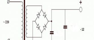
The 12 volt DC power supply consists of three main parts:
- A step-down transformer from a conventional input alternating voltage of 220 V. At its output there will be the same sinusoidal voltage, only reduced to approximately 16 volts at idle - without load.
- Rectifier in the form of a diode bridge. It “cuts off” the lower half-sine waves and puts them up, that is, the resulting voltage varies from 0 to the same 16 volts, but in the positive region.
- A high-capacity electrolytic capacitor that smooths out the half-sine voltage, making it approach a straight line at 16 volts. This smoothing is better, the larger the capacitor capacity.
The simplest thing you need to obtain a constant voltage capable of powering devices designed for 12 volts - light bulbs, LED strips and other low-voltage equipment.
A step-down transformer can be taken from an old computer power supply or simply bought in a store so as not to bother with windings and rewinding. However, in order to ultimately reach the desired 12 volts of voltage with a working load, you need to take a transformer that lowers the volts to 16.
For the bridge, you can take four 1N4001 rectifier diodes, designed for the voltage range we need or similar.
The capacitor must have a capacity of at least 480 µF. For good output voltage quality, you can use more, 1,000 µF or higher, but this is not at all necessary to power lighting devices. The operating voltage range of the capacitor is needed, say, up to 25 volts.
power unit
We will not consider purchasing any units or transformers, and if we do buy it, it will be a new battery!
We will consider using what we have on hand. I’ll say right away that the charger from the same screwdriver is only suitable for drilling overripe bananas, its power is too low. Ideally, a step-down, powerful 12 V transformer, for example from a computer uninterruptible power supply, would be suitable. The power of such a transformer is usually 350-500 watts. But I didn’t have such a transformer, but I had a lot of computer power supplies. I am sure that if someone has various electronic junk, ATX computers are definitely lying around in it.
This is one of the first representatives of computer ATX power supplies.
The computer ATX unit is quite suitable for a screwdriver; the load capacity on the +12 volt bus allows you to remove currents of 10-20 amperes. I would like to dispel a small myth - it will not be possible to stuff the unit into the battery housing of a screwdriver, the ATX board is too large. You will have to make a separate case for the block or leave it in its original metal case. The disadvantage of the original case is sensitivity to dust, and even the smallest repair requires a lot of dust.
A rather weak unit, the load on the +12V bus is only 10 A. If possible, it is better to choose units with a more powerful twelve-volt bus.
PCB manufacturing
Prepare foil PCB by treating the metal layer with a solution of hydrochloric acid. If there is none, then you can use the electrolyte poured into car batteries. This procedure will degrease the surface. Wear rubber gloves to prevent solutions from getting on your skin, as this can cause severe burns. After this, rinse with water and soda (you can use soap to neutralize the acid). And you can apply a drawing of the printed circuit board.
You can make a drawing using a special computer program or manually. If you are making a regular 12V 2A power supply, and not a switching one, then the number of elements is minimal. Then, when applying a drawing, you can do without modeling programs; just apply it to the surface of the foil with a permanent marker. It is advisable to make two or three layers, allowing the previous one to dry. The use of varnish (for example, for nails) can give good results. True, the drawing may turn out uneven due to the brush.
Assembly of filtration blocks
Before connecting the 12 volt power supply, it is recommended to install special filters that will help the operation of household appliances connected to the device. To power household appliances, an LC circuit is usually used. Where the rectifier with the plus value comes out of the device, a choke must be connected. Electric current must pass through it.
The connection of the second pin goes to the common electrical wire with a minus value. An electrolytic capacitor helps stabilize the electric current. How does this happen? We will look at this issue in a little more detail.
How to connect a power supply to LED products
In order for the backlight connection to be carried out efficiently, you must adhere to the following scheme:
Connection diagram for power supply and tape
To connect you need a wire and a plug. A switch should be installed on the wire. After this we do the following:
- on the adapter we find four contacts: zero, phase, COM (the tape is connected here) and V+ (for output voltage);
- We expose the end of the wire and connect it to zero and phase. After that we plug it into the socket. If the green LED on the power supply lights up, then the device is ready for operation. We carry out the remaining manipulations in accordance with the diagram.
That's all the connection is. So, now you know how to choose an adapter for connecting a 12 V LED strip or make it yourself. Remember that a properly selected device is the key to creating high-quality lighting and a long period of its operation.
Tips for using a corded screwdriver
Experts recommend following certain rules to everyone who decides to reconstruct a screwdriver and construct a 12V power supply for a screwdriver with their own hands. Instructions for upgrading the tool include the following tips:
- You can use a corded screwdriver as much as you like without worrying about the battery running out. However, such an instrument needs rest. Therefore, take five-minute breaks to avoid overheating or overloading the instrument.
- When working with a screwdriver, do not forget to secure the wire in the elbow area. This will make it more convenient to operate the device, and the cord will not interfere when screwing in screws.
- Carry out systematic cleaning of the screwdriver power supply from accumulations of dust and dirt deposits.
- The new battery is provided with grounding.
- Do not use more than one extension cord to connect to the network.
- This device is not recommended for use in high-altitude work (from two meters).
By adhering to the recommendations described above, you will be able to operate the screwdriver longer and prolong its working condition, postponing the purchase of a new tool for a long time.
Now you know what power supply is needed for a 12V screwdriver, and what materials to use to make such a design yourself at home. There is no need to replace the old screwdriver with a new one. A radical decision should be made only if the unit is completely out of order, and a “dead” battery is not a problem for the craftsman. You just need to have an understanding of radio engineering and arm yourself with a soldering iron. Then it will be easier to cope with the task.
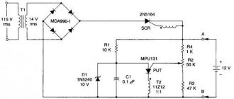
Voltage stabilization
After manufacturing the transformer, be sure to measure the voltage at the terminals of its secondary winding. If it exceeds 12 Volts, then stabilization is necessary. Even the simplest 12V power supply will work poorly without this. It should be taken into account that the voltage in the supply network is not constant. Connect a voltmeter to an outlet and take measurements at different times. So, for example, during the day it can jump to 240 Volts, and in the evening drop even to 180. It all depends on the load on the power line.
If the voltage changes in the primary winding of the transformer, it will also be unstable in the secondary. To compensate for this, you need to use devices called voltage stabilizers. In our case, you can use zener diodes with suitable parameters (current and voltage). There are many zener diodes, select the necessary elements before making a 12V power supply.
There are also more “advanced” elements (type KR142EN12), which are a set of several zener diodes and passive elements. Their characteristics are much better. There are also foreign analogues of similar devices. You need to become familiar with these elements before you decide to make a 12V power supply yourself.
Mock Tests
Before starting to build a working structure, you should test everything on the knees, make sure that the screwdriver is operating stable under load and that there is no severe overheating in the power supply.
We take the computer power supply and check it: plug it into the network, find green in the output bundle of wires (they say it can be a different color, but I always came across green ones) and connect it with a jumper to any of the black ones (all black wires at the output are the common output, in our case it is a minus). The unit should turn on and a voltage of 12 volts will appear between the black and yellow wires. You can check this with a multimeter or by connecting any computer cooler to the named terminals.
If everything is in order and the unit produces about 12 volts on the yellow (+) and black (-) terminals, continue. If there is no voltage at the output, we look for another unit or repair this one; this separate topic will be described separately.
We cut off the plug from the output of the block and take 3-4 yellow and black wires coming from the block and connect them in parallel. When cutting off the plug, do not forget about the green starting conductor, it must be shorted to black. We received a 12 V source with a decent current load capacity of 10-20 A, the currents depend on the model and power of the unit.
Now we need to connect our 12 V to the terminals of the screwdriver without a battery; we look at the polarity of the connection using the battery. Well, we check the screwdriver - at idle speed, then slowing down by hand. At this stage, I encountered a problem: when I press the button fully, the screwdriver works, but when I slowly, smoothly press the screwdriver button, the power supply goes into protection. To reset the protection, you must disconnect the unit from the network and turn it on again. This won’t work at all, we need to somehow correct this instability.
I pulled the block board out of the case and additionally hooked up a multimeter to constantly monitor the voltage
In my opinion, this phenomenon may occur due to the fact that the power supply and the screwdriver button are controlled by PWM controllers; due to interference along the power wires, the controllers somehow interfere with each other. We are trying to solve this problem using an improvised LC filter.
I assembled the filter in 5 minutes from what was at hand: 3 electrolytic capacitors of 1000 uF at 16 volts, a non-polar capacitor of less than 1 uF and wound 20 turns of copper wire with a diameter of 2 mm on a ferrite ring from another unit. Here is his diagram:
And this is what he looks like. This is a purely trial version, in the future this design will be transferred to the battery housing of the screwdriver and will be made more accurately.
We check the entire structure: the block does not go into protection in any position of the button, great! Now you can try tightening several screws - all in a bunch. It seems that the screwdriver will be able to tighten larger screws.
Well, now you need to remove all the snot and piles of wires, remove the “dead cans” from the battery case, replace them with an LC filter, and test the screwdriver in more realistic conditions.
Device layout
If we want to make a decent device that we won’t be ashamed to attach later as a permanent power supply, say, for a chain of LEDs, we need to start with a transformer, a board for mounting electronic components and a box where all this will be fixed and connected. When choosing a box, it is important to consider that the electrical circuits heat up during operation. Therefore, it is good to find a box that is suitable in size and with holes for ventilation. You can buy it in a store or take a case from a computer power supply. The latter option may be cumbersome, but as a simplification you can leave the existing transformer in it, even along with the cooling fan.
Power supply housing Power supply housing
On the transformer we are interested in the low-voltage winding. If it reduces the voltage from 220 V to 16 V, this is an ideal case. If not, you'll have to rewind it. After rewinding and checking the voltage at the output of the transformer, it can be mounted on the circuit board. And immediately think about how the circuit board will be attached inside the box. It has mounting holes for this.
Low voltage winding Circuit board
Further installation steps will take place on this mounting board, which means that it must be sufficient in area, length and allow the possible installation of radiators on diodes, transistors or a microcircuit, which must still fit into the selected box.
Diode bridge
We assemble the diode bridge on the circuit board, you should get such a diamond of four diodes. Moreover, the left and right pairs consist equally of diodes connected in series, and both pairs are parallel to each other. One end of each diode is marked with a stripe - this is indicated by a plus. First we solder the diodes in pairs to each other. In series - this means the plus of the first is connected to the minus of the second. The free ends of the pair will also turn out - plus and minus. Connecting pairs in parallel means soldering both pluses of the pairs and both minuses. Now we have the output contacts of the bridge - plus and minus. Or they can be called poles - upper and lower.
Diode bridge circuit
The remaining two poles - left and right - are used as input contacts, they are supplied with alternating voltage from the secondary winding of the step-down transformer. And the diodes will supply a pulsating voltage of constant sign to the bridge outputs.
If you now connect a capacitor in parallel with the output of the bridge, observing the polarity - to the plus of the bridge - plus of the capacitor, it will begin to smooth out the voltage, and as well as its capacitance is large. 1,000 uF will be enough, and even 470 uF is used.
Attention! An electrolytic capacitor is an unsafe device. If it is connected incorrectly, if voltage is applied to it outside the operating range, or if it is overheated, it may explode. At the same time, all its internal contents scatter around the area - tatters of the case, metal foil and splashes of electrolyte. Which is very dangerous.
Well, here we have the simplest (if not primitive) power supply for devices with a voltage of 12 V DC, that is, direct current.
Assembling the device
Prepare all the necessary parts in advance: microcircuits, transformers, diode bridge, inductor, protection unit, capacitor filter, voltage stabilizer.
Typically, the windings of transformers can withstand voltages up to 250 W. If you make a secondary winding, it conducts voltage up to 50 W. The winding can be purchased at a special store or removed from an old electrical appliance.
In order to make a huge number of electrical tracks, you will need a microcircuit marked PDIP-8.
To get a diode bridge, you will need four 0.2x0.5 mm diodes. The protection unit can be made from fuses (you will need two) of the FU2 brand.
To connect all spare parts, use a special diagram and instructions, which describe everything in an extremely accessible way.
Often, after dry diagrams there may be a photo of homemade devices, which clearly shows the design. Additionally, you can also find diagrams on how to repair the power supply if it breaks.
Filtering and cutting off the variable component
Filters occupy an important place in rectifier technology. Take a look at the 12V power supply, which is the most common circuit. It consists of a diode bridge, a capacitor, and a resistance. The filters cut off all unnecessary harmonics, leaving a constant voltage at the output of the power supply. For example, the simplest filter is an electrolytic capacitor with a large capacity. If you look at its operation at constant and alternating voltages, its operating principle becomes clear.
In the first case, it has a certain resistance and in the equivalent circuit it can be replaced with a constant resistor. This is relevant for carrying out calculations using Kirchhoff’s theorems.
In the second case (when alternating current flows), the capacitor becomes a conductor. In other words, it can be replaced with a jumper that has no resistance. It will connect both outputs. Upon closer examination, you can see that the alternating component will go away, because the outputs close while current flows. Only constant tension will remain. In addition, to quickly discharge the capacitors, the 12V power supply you assemble yourself must be equipped with a resistor with a high resistance (3-5 MOhm) at the output.
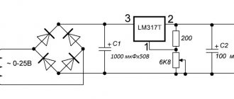
Voltage stabilizer LM7805, LM7809, LM7812
You probably noticed that the voltage in the outlet is not equal to 220 V, but varies within certain limits. This is especially noticeable when connecting a powerful load. If you do not apply special measures, then it will change in a proportional range at the output of the power supply. However, such vibrations are extremely undesirable and sometimes unacceptable for many electronic elements. Therefore, the voltage after the capacitor filter must be stabilized. Depending on the parameters of the powered device, two stabilization options are used. In the first case, a zener diode is used, and in the second, an integrated voltage stabilizer is used. Let's consider the application of the latter.
In amateur radio practice, voltage stabilizers of the LM78xx and LM79xx series are widely used. Two letters indicate the manufacturer. Therefore, instead of LM there may be other letters, for example CM. The marking consists of four numbers. The first two - 78 or 79 - mean positive or negative voltage, respectively. The last two digits, in this case instead of two X's: xx, indicate the value of the output U. For example, if the position of two X's is 12, then this stabilizer produces 12 V; 08 – 8 V, etc.
For example, let's decipher the following markings:
LM7805 → 5V positive voltage
LM7912 → 12 V negative U
Integrated stabilizers have three outputs: input, common and output; designed for current 1A.
If the output U significantly exceeds the input and the maximum current consumption is 1 A, then the stabilizer gets very hot, so it should be installed on a radiator. The design of the case provides for this possibility.
If the load current is much lower than the limit, then you don’t have to install a radiator.
Design and principle of operation
A transformer power supply differs from a conventional power supply by the presence of a step-down device, which allows you to reduce the voltage supplied to the network from 220V to 12V. These devices also use a rectifier, which is made of 1, 2 or 4 semiconductor-type diodes, depending on the type of circuit.
Power supplies in this category use transformers that use three main components:
- The core is a special metal alloy or ferromagnetic;
- Network primary winding which is powered by 220V;
- The secondary winding is used with a reducing effect - a rectifier is connected to it.
Otherwise, this unit is identical in principle of operation, structure and design to a conventional power supply. Thanks to this, it is possible to connect devices of various categories.
The rectifier used is determined by the schematic device, which depends on the values to which the voltage level needs to be brought. For example, in the case of voltage doubling, two semiconductors are used. After the conductor, it is necessary to use an electrolytic capacitor in the design device.
Regulatory process
It is common practice to use regulated power supplies. When installing the stabilizer, it is necessary to mount a special wire to which a variable resistor should be connected.
The regulator allows you to stabilize current indicators to optimal values and prevents burnout of the mechanism. To enhance the safety of the assembled unit, you can install an electronic voltmeter at the output of the system, which will help monitor the current voltage in the system.
Assembling a 12 Volt power supply is not difficult even for a person with minimal knowledge in the field of assembling any devices. To do this, you can use step-by-step instructions with photos at each stage. Having the necessary parts and step-by-step instructions, you can assemble any mechanism.
When connecting to electrical appliances, you must consult with a master electrician, who will check the correct assembly, which will prevent problems with the operation of the device.
Rules for choosing components
To make your own power supply with a transformer, you need to select the right components. In this article, we figured out how to calculate the values of the necessary elements of the device, which transformers, rectifiers and filters can be used in a power supply of this type. For convenience, I offer the table below, it will help when choosing components:
This table shows the optimal values and ratios of device power and technical characteristics of all components used in the design. The capacitance of the capacitors must provide the specified ripple at the rate of 1 µF per 1 W in terms of output power. The electrolytic capacitor must be selected for a voltage of 350V or more.
Components of the device
The mechanism we are assembling today consists of three parts:
step-down transformer, which is the most important and integral part; a capacitor, with the help of which the current voltage is stabilized to optimal readings; diodes that are necessary to assemble a diode bridge with your own hands.
Each part is very important. If an error is made in any of them during assembly, this will lead to the fact that the assembled unit and the household electrical appliance connected to the system will not work correctly. And also the assembled device may not turn on at all. Let's look at each of the components of the mechanism in more detail.
Power transformer
The power transformer operates at high frequencies (up to several tens of kilohertz), so it can be made on a core made of ferrite rather than transformer iron. Also, due to the increased frequency, its dimensions will be smaller than that of a network one, designed for conversion at a frequency of 50 Hz. The calculation of a pulse transformer is quite extensive. You can understand it for general development, but for practical purposes it is better to use some program, including online services.
Interface of the Lite-CalcIT program.
The Lite-CalcIT program is popular. She can calculate a transformer for an existing core, or she can select the optimal one based on the entered data.
Assembly of the working structure
For ease of use and connection, I brought the cord from the power supply into the battery case. I took a 3.5 meter long cord that was available. I removed all the battery cells from the battery and installed an LC filter. Now, if I somehow get a working battery, I can always put it on a screwdriver and put the power supply away as a reserve. I didn’t throw the batteries out of the battery, I have an idea where to use them, but that’s a topic for another review.
Since the cord connecting the unit to the screwdriver has a certain resistance and inductance, you can try to close the terminals of the L1 coil with a jumper. In theory, this could increase power by a tiny amount.
The screwdriver feels great with a cord, but to be honest, it seemed a little weak to me when braking by hand. But trial tightening of the self-tapping screws dispelled my doubts: self-tapping screws 35 mm long can easily be screwed into 20 mm plywood. This means that a screwdriver will cover most repair needs.
I cut off all the output wires from the block, leaving the green starting wire; I soldered its end to the common conductor of the board, where all the black ones are soldered. It's best to carefully desolder all the wires, but my soldering iron was too weak for this and had to be cut. I soldered two short, hard copper wires to the common contact and +12 (where the yellow ones are soldered) and connected them through the terminal block to the cord to the Shura.
This is where we will finish this review; we have achieved what we wanted - the screwdriver works perfectly with a computer power supply. In the future, I plan to make a high-quality plywood case without cracks for the power supply board - tests have shown that the heatsinks on the board do not heat up at all and you don’t have to worry about overheating of the elements in a closed case.
How to etch a board
Place the prepared and dried board in a ferric chloride solution. Its saturation should be such that the copper is corroded as quickly as possible. If the process is slow, it is recommended to increase the concentration of ferric chloride in the water. If this does not help, then try heating the solution. To do this, fill a container with water, place a jar of solution in it (do not forget that it is advisable to store it in a plastic or glass container) and heat over low heat. Warm water will heat the ferric chloride solution.
If you have a lot of time or do not have ferric chloride, then use a mixture of salt and copper sulfate. The board is prepared in a similar way and then placed in the solution. The disadvantage of this method is that the power supply board is etched very slowly; it will take almost a day for all copper to completely disappear from the surface of the PCB. But for lack of a better one, you can use this option.
Transformer selection
The voltage converting device is one of the main transformer components. Here the alternating 220-volt voltage is converted into something similar to itself, but with a slightly reduced amplitude.
A conventional step-down device, necessary to reduce the voltage from the usual 220-volt to 12-volt, can be used as a transformer-type machine.
It is optimal to use a 470 μF capacitor with a 25-volt voltage for the device. Why would this be the best option? This is due to the fact that when the voltage leaves the unit, it becomes higher than the standard voltage of 12V. When the mechanism starts working, the voltage returns to standard values (12 V).
How to make a power supply?
A novice radio amateur will ever have a question: how to make a simple power supply yourself at home.
First of all, you need to determine which power supply is needed and for what exact purposes. Power supplies can be used in a variety of applications by many DIYers.
In order to make your own power supply, you need to understand how it is designed and how it works. This will help in the future to carry out minor repairs to the device if necessary.
We determine which block is needed - adjustable or not. In advance, before performing work, you need to find all the instructions and power supply diagrams that will help you make the device you need.
Adjustable is a device whose output voltage can be changed (changes within the range from 3 to 12 volts are allowed). For example, if we want to get 7 or 10 volts, we will only need to turn the regulator knob.
An unregulated device has a fixed output voltage that cannot be changed. For example, the “Electronics” D2-27 power supply cannot be adjusted, and it always produces 12 volts at the output.
The most interesting for radio amateurs are regulated power supplies. They allow you to power quite a lot of devices (homemade or industrial) that will require different supply voltages.
Photos of a homemade power supply can be found in magazines for radio amateurs or on the Internet.
Another power supply, 12 Volt 30 Ampere and 360 Watt
Continuing the topic of power supplies, I ordered another power supply, but this time more powerful than the previous one. The review will not be very long, but as always, I will inspect, disassemble, and test. In fact, this review is only an intermediate step towards testing more powerful power supplies that are already on their way to me. But I thought that this option also cannot be ignored, so I ordered it for review.
Just a few words about the packaging. An ordinary white box, only the article number is the identifying mark, that's all.
When compared with the power supply from the previous review, it turned out that the one under review is simply a little longer. This is due to the fact that the reviewed power supply has active cooling, therefore, with almost the same volume of the case, we have one and a half times more power. The dimensions of the case are 214x112x50mm.
All contacts are connected to one terminal block. The purpose of the contacts is stamped on the body of the power supply; this option is a little more reliable than a sticker, but less noticeable. The lid closes with noticeable force and is firmly fixed when closed. When opened, full access to the contacts is provided. Sometimes the power supply unit encounters a situation where the lid does not open completely, so now I definitely check this point.
1. There is a sticker on the power supply case indicating the basic parameters, power, voltage and current. 2. There is also a 115/230 Volt input voltage switch, which in our networks is superfluous and not always safe. 3. The power supply was released almost a year ago. 4. Near the terminal block there is an operation indication LED and a trimming resistor for changing the output voltage.
There is a fan on top. As I wrote in the previous review, a power of 240-300 Watts is the maximum for power supplies with passive cooling. Of course, there are fanless power supplies with higher power, but they are much less common and are very expensive, so the introduction of active cooling aims to save money and make the power supply cheaper.
The cover is fixed with six small screws, but at the same time it sits tightly on its own; the body is aluminum and, like other power supplies, acts as a radiator.
As a comparison, I’ll give a photo next to a 240-watt power supply. It can be seen that they are basically the same, and in fact the 360 Watt PSU differs from its younger brother only in the presence of a fan and some small adjustments associated with higher output power.
For example, their power transformer has the same size, but the output choke of the one under review is noticeably larger. A common feature of both power supplies is very free installation, and if this is justified for a power supply with passive cooling, then with active cooling the size of the case could be safely reduced.
Check functionality before further disassembly. Initially, the output voltage is slightly higher than the stated 12 Volts, although by and large this does not matter, I am more interested in the tuning range and it is 10-14.6 Volts. At the end I set it to 12 Volts and move on to further inspection.
Oddly enough, the capacitance of the input capacitors coincides with that indicated on their case. The capacitance of each capacitor is 470 µF, the total is about 230-235 µF, which is noticeably less than the recommended 350-400 that is required for a 360-watt power supply. Ideally, there should be capacitors with a capacity of at least 680 µF each.
The output capacitors have a total capacitance of 10140 µF, which is also not very much for the declared 30 Amperes, but often capacitors of branded power supplies have such a capacitance.
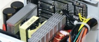
Transistors and output diodes are pressed to the body through a heat distribution plate; only heat-conducting rubber acts as insulation. Typically, more expensive power supplies use a cap made of thicker rubber, which completely covers the component, and if it is not particularly needed for output diodes, then it would obviously not hurt for high-voltage transistors. Actually, for this reason, I recommend grounding the power supply housing for safety reasons. The heat distribution plates are pressed against the aluminum body, but there is no thermal paste between them and the body.
After the incident with one of the power supplies, I now always check the quality of the clamping of the power elements. There are no problems with this here, however, usually there are no problems with double elements; more often the problem is when there is only one powerful element and it is pressed with an L-shaped bracket.
The fan is the most common one, with plain bearings, but for some reason the voltage is 14 Volts. Size 60mm.
Let's look further. The board is held on by three screws and fastening elements for power components. There is a protective insulating film at the bottom of the case.
The filter is quite standard for such power supplies. The input diode bridge is marked KBU808 and is designed for current up to 8 Amps and voltage up to 800 Volts. There is no radiator, although with such power it is already desirable.
1. A thermistor with a diameter of 15 mm and a resistance of 5 Ohms is installed at the input. 2. There is an X2 class noise suppressing capacitor in parallel to the network. 3. Noise-suppressing capacitors that are directly connected to the network are installed in class Y2 4. An ordinary high-voltage capacitor is installed between the common output wire and the power supply housing, but in this place it is sufficient since, in the absence of grounding, it is connected in series with the class Y2 capacitors shown above.
PWM controller KA7500, analogue of the classic TL494. The circuit is more than standard; manufacturers simply churn out identical power supplies, which differ only in the ratings of some components and the characteristics of the transformer and output choke. The output transistors of the inverter are also classic inexpensive power supplies - MJE13009.
1. As I wrote above, the input capacitors have a capacity of 470 μF and what is interesting is that if the capacitors have an initially unclear name, then more often the real capacity is indicated, and if it is a fake, for example Rubicon g
, then it is often underestimated. Here's an observation. 2. The magnetic core of the output transformer has dimensions of 40x45x13mm, the winding is impregnated with varnish, although very superficially. 3. Next to the transformer there is a connector for connecting a fan. Usually in the description of such power supplies they indicate automatic speed control, but in fact it is not here. Although the fan changes speed within a small range depending on the power output, this is simply more of a side effect. When turned on, the fan operates very quietly, and reaches full power at a current of about 2.5 Amperes, which is less than 10% of the maximum. 4. At the output there is a pair of MBR30100 diode assemblies of 30 Amperes 100 Volts each.
1. The dimensions of the output choke are noticeably larger than those of the 240 Watt version, wound in three wires on two 35/20/11 rings. 2. As expected after a preliminary check, the output capacitors have a capacity of 3300 μF, since they are new, the total showed not 9900, but 10140 μF, a voltage of 25 Volts. Manufacturer known to everyone noname. 3. Current shunts for short-circuit and overload protection circuits. Usually they install one such “wire” for 10 Amperes of current, respectively, here there is a 30 Ampere power supply and three such wires, but there are 7 places, so I will assume that there is a similar option but with a current of 60 Amps and a lower voltage. 4. Here’s a small difference: the components responsible for blocking at a reduced output voltage were moved closer to the output, although they even retained their positional positions according to the diagram. Those. R31 in the 36 Volt power supply circuit corresponds to R31 in the 12 Volt power supply circuit, although they are in different places on the board.
At a quick glance, I would rate the quality of soldering as a solid four, everything is clean and tidy.
The soldering is quite high quality; protective slots are made on the board in narrow places.
But there was still a fly in the ointment. Some elements are not soldered. The location is especially unimportant, the fact itself is important. In this case, poor soldering was found on one of the fuse and capacitor terminals of the output voltage undervoltage protection circuit. It only takes a few minutes to fix, but as they say, “the spoons were found, but the sediment remained.”
Since I had already drawn a diagram of such a power supply, in this case I simply made adjustments to the already existing diagram. In addition, I highlighted in color the elements that have changed. 1. Red - elements that change depending on changes in output voltage and current 2. Blue - changing the ratings of these elements with a constant output power is not clear to me. And if it’s partly clear with the input capacitors, they were indicated as 680 uF, but actually showed 470, then why did they increase the capacitance of C10 by one and a half times?
We've finished the inspection, let's move on to the tests, for this I used the usual “test bench”, albeit supplemented with a Wattmeter. 1. Electronic load 2. Multimeter 3. Oscilloscope 4. Thermal imager 5. Thermometer 6. Wattmeter 7. Pen and paper.
At idle there is virtually no pulsation.
A small clarification to the test. On the electronic load display you will see current values noticeably lower than what I will write. The fact is that the load is capable of loading high currents in hardware, but is limited in software at 16 Amperes. In this regard, we had to make a “feint with our ears”, i.e. calibrate the load for double current, as a result, 5 Amps on the display are equal to 10 Amps in reality.
At load currents of 7.5 and 15 Amps, the power supply behaved identically; the total ripple range in both cases was about 50 mV.
At load currents of 22.5 and 30 Amps, the pulsations increased noticeably, but were at the same level. The ripple level increased at a current of about 20 Amps. As a result, the full swing was 80mV. I note very good stabilization of the output voltage; when the load current changed from zero to 100%, the voltage changed by only 50 mV. Moreover, as the load increases, the voltage increases rather than decreases, which can be useful. During the warm-up process, the voltage did not change, which is also a plus.
I summarized the test results into one table, which shows the temperature of the individual components. Each stage of the test lasted 20 minutes, the full load test was carried out twice for thermal warm-up. The cover with the fan was inserted into place, but not screwed; to measure the temperature, I removed it without disconnecting the power supply and the load.
As an addition, I made several thermograms. 1. Heating of the wires to the electronic load at maximum current; thermal radiation from internal components is also visible through the cracks in the housing. 2. Diode assemblies have the greatest heating; I think if the manufacturer had added a radiator as is done in the 240 Watt version, the heating would have decreased significantly. 3. In addition, heat removal from this entire structure was a big problem, since the total dissipated power of the entire structure was more than 400 Watts.
By the way, about heat dissipation. When I was preparing the test, I was more afraid that it would be difficult for the load to work at such power. In general, I have already conducted tests at this power, but 360-400 Watts is the maximum power that my electronic load can dissipate for a long time. For a short time, it can handle 500 watts without any problems. But the problem came out elsewhere. On the radiators of the power elements, I have thermal switches designed for 90 degrees. They had one contact soldered, but the second one could not be soldered, so I used terminal strips. At a current of 15 Amps through each switch, these contacts began to heat up quite strongly and operation occurred earlier; this structure also had to be forcibly cooled. And besides, we had to partially “unload” the load by connecting several powerful resistors to the power supply.
But in general, switches are designed for a maximum of 10 Amps, so I did not expect them to operate normally at a current 1.5 times their maximum. Now I’m thinking about how to remake them, apparently I’ll have to make electronic protection controlled by these thermal switches.
And besides, now I have another task. At the request of some readers, I ordered 480 and 600 Watt power supplies for review. Now I’m thinking about how it’s better to load them, since my load definitely won’t be able to withstand such power (not to mention currents up to 60 Amps).
Just like last time, I measured the efficiency of the power supply, I plan to carry out this test in future reviews. The test took place at power 0/33/66 and 100%
Input - Output - Efficiency. 5.2 - 0 - 0 147.1 - 120.3 - 81.7% 289 - 241 - 83.4% 437.1 - 362 - 82.8%
What can we say in the end? The power supply passed all the tests and showed pretty good results. In terms of heating, there is even a noticeable margin, but I would not recommend loading it above 100%. I was pleased with the very high stability of the output voltage and the lack of dependence on temperature. The things I didn’t really like include the nameless input and output capacitors, soldering flaws in some components, and mediocre insulation between the high-voltage transistors and the heatsink.
Otherwise, the power supply is a very ordinary one, it works, holds voltage, and doesn’t get too hot.
That's all, as usual, I'm waiting for questions.
The product was provided for writing a review by the store. The review was published in accordance with clause 18 of the Site Rules.
⇡#“Gaming PCs do not need 1 kW units” - commentators under articles on 3DNews.ru
We often see comments like this when it comes to gaming PCs. In the vast majority of cases - and we have found this out in practice - this is so. However, in 2022 there is a system that can amaze with its energy consumption.
We are, of course, talking about an extreme build in its, so to speak, maximum combat form. Not long ago, an article was published on our website “What the fastest gaming PC of 2022 can do. Testing a system with two GeForce RTX 2080 Ti in 8K resolution” - in it we talked in detail about the performance of a pair of the fastest GeForce video cards in 4K and 8K resolution. The system is fast, but the components are selected in such a way that it is very easy to make it even faster. In addition, it turned out that overclocking the Core i9-9900K to 5.2 GHz is completely useful in the case of the GeForce RTX 2080 Ti SLI array and Ultra HD games. Only at its peak, as we see, such an overclocked configuration consumes more than 800 W. Therefore, for such a system under such conditions, a kilowatt power supply will definitely not be superfluous.
How much current does a screwdriver consume?
Before choosing a suitable power supply, you need to understand what current consumption you need to count on. Unfortunately, cordless screwdriver manufacturers do not indicate the current consumed by the motor. The capacity of the battery itself in ampere-hours, which is necessarily indicated on the battery, does not allow us to understand how much current the screwdriver consumes in operating mode
. The maximum that the manufacturer can indicate is the power in watts, but this is very rare, usually the power is indicated directly in torque.
If the power in watts is still indicated, we can have an idea of the current consumption and select an appropriate power supply with a small current/power margin. To calculate the current, it is enough to divide the power in watts by the operating voltage of the screwdriver, in this case it is 12 volts. So, if the manufacturer indicated a power of, for example, 200 watts - 200:12 = 16.6 A - this is the current consumed by the screwdriver in operating mode.
However, the indicated power is very rare and there is no universal figure that characterizes all 12-volt screwdrivers. You need to understand that when the motor shaft is fully braked, the currents can significantly exceed the rated ones and calculating this value is not very easy. At the same time, an analysis of various forums and our own experience has shown that a current of 10 A is often sufficient to operate a screwdriver; this is enough to perform many screwing and drilling functions. It is known that current surges during complete braking of the shaft can exceed 30 A.
Well, what conclusion can be drawn from all this? A 12 V power supply providing 10 A current is suitable for a screwdriver; if it is possible to use a 20-30 A unit, this is even better. These are average figures that apply to most screwdrivers.
General structure
The block diagram of a power supply with transformer action is of the following type:
However, some transformer-type chargers do not use the last two elements. Essentially, the main ones are the transformer and the rectifier; they are responsible for reducing the voltage, but the filter and stabilizer provide additional protection and regulation of the voltage values supplied to the device.
In the electronics market today, the most popular are unipolar transformer power supplies. The diagram of this device looks like this:
We’ll talk about the design of the transformer itself and the principles of its operation further. A two-pole power supply of this category has the following circuit:
Unlike the first circuit, this one uses a transformer with identical paired secondary windings that are connected in series.
Transformer
One of the main elements of a transformer design is the core. In power supplies it can be W-shaped or U-shaped; in rare cases, toroidal cores are used. They contain transformer windings of two layers: a secondary one on top of a primary one.
Design
When assembling the structure, a special formula is used that allows you to calculate the required dimensions of the transformer:
(1/N)~F*S*B
This formula uses the following values:
- N – number of turns per 1 volt;
- F – frequency level in alternating voltage;
- S – cross-section of the magnetic circuit;
- B – magnetic field induction in the magnetic circuit.
In this way, the design features of the transformer can be calculated. In transformer power supplies, toroidal, rod and armor types of windings are used.
Their appearance is shown in the picture below:
To calculate the secondary winding, you can use the following technique. 10 turns are wound, the transformer is assembled and, in compliance with safety regulations, the primary winding is connected to the electrical network using the standard method. Then the voltage level is measured at the output from the secondary winding. The resulting values are divided by 10, after which 12 is divided by 10. This determines the number of turns required to generate a voltage of 12V.
Basic elements and principle of operation of power supplies
The main part is a step-down transformer, and if it does not have the necessary parameters, the secondary winding is rewound manually and the required output voltage is obtained. By means of a transformer, the voltage of the 220 volt network is reduced to 12, which goes further to the consumer.
There is no fundamental difference between standard devices and those with a rewound secondary winding; the main thing is to correctly calculate the cross-section of the wire and the number of turns on the winding.
Next, the current goes to the rectifier. Consists of semiconductors, such as diodes. A diode bridge, in different circuits, can consist of one, two or four diodes. After the rectifier, the current flows to the capacitor; it is also desirable to include a zener diode with the appropriate characteristics in the circuit to produce a stable voltage.
Principle of operation
A transformerless transistor unit works as follows. 220 V is rectified by a bridge with a capacitor and supplied to the stabilizers. They are all made according to the same circuit, but are designed for different voltages. The first limits the network potential at 150-180 V, the second stabilizer reduces it by about 2-3 times. The third one produces the required voltage. By changing the zener diode D3, you can get a transformerless power supply, for example, 12 or 5 volts.
The RC block is a voltage divider. In its upper (according to the diagram) arm there is a capacitor C1, which represents a reactive resistance for alternating current (does not consume energy at all). At the bottom there is a diode bridge VD1-4 with a load (zener diode, transistor, microcircuit, etc.).
The input voltage comes to the divider, is rectified by the bridge and goes to the stabilizer, which limits it to the required value.
Battery or power supply from computer equipment
A device that supports the charge of a PC or laptop is quite suitable for achieving this goal. The process of introducing a power supply into a screwdriver is as follows:
The screwdriver body is completely disassembled. The old power supply is removed and the wires are unsoldered. The wiring of the new unit is connected to the wiring of the old one, which powers the previous battery.
When carrying out such an operation, it is important to observe polarity! Turn on the screwdriver and check for functionality. If all wires are connected correctly, the machine will work. There is a hole in the body of the device where a plug with a charging connector can easily be placed.
By upgrading a screwdriver in this way, you get an improved device, which is now also recharged during operation like a laptop from a 220V network. The new power source is mounted inside the screwdriver, securing it with glue. The remaining body elements are returned to their place and the product is twisted, giving it its original appearance.
That's all! Now you know how to turn a cordless screwdriver into a corded one.
How to get uninterrupted power?
It is enough to connect the power supply in parallel with the battery so that when the power is turned off, all devices continue to operate in normal mode. When the network is connected, the power supply charges the battery, the principle is similar to the operation of the power supply of a car. And when the 12V uninterruptible power supply is disconnected from the network, voltage is supplied to all equipment from the battery.
But there are times when it is necessary to obtain a mains voltage of 220 Volts at the output, for example, to power personal computers. In this case, it will be necessary to introduce an inverter into the circuit - a device that converts a direct voltage of 12 Volts into an alternating voltage of 220. The circuit turns out to be more complicated than that of a simple power supply, but it can be assembled.
⇡#What power is needed for modern gaming PCs
Let me note again: this article is to a certain extent tied to the “Computer of the Month” section. Therefore, if you are visiting us for the first time, I recommend that you at least read the August issue. Each “Computer of the Month” covers six assemblies, mostly gaming ones. I used similar systems for this article. Let's get acquainted:
- The combination of Ryzen 5 1600 + Radeon RX 570 + 16 GB of RAM is an analogue of the starting assembly (35,000-37,000 rubles per system unit, excluding the cost of software).
- The combination of Ryzen 5 2600X + GeForce GTX 1660 + 16 GB of RAM is an analogue of the basic assembly (50,000-55,000 rubles).
- A combination of Core i5-9500F + GeForce RTX 2060 + 16 GB of RAM is an analogue of the optimal assembly (70,000-75,000 rubles).
- A combination of Core i5-9600K + GeForce RTX 2060 + 16 GB of RAM is another optimal build option.
- A combination of Ryzen 7 2700X + GeForce RTX 2070 + 16 GB of RAM is an analogue of an advanced build (100,000 rubles).
- The Ryzen 7 2700X + Radeon VII + 32 GB RAM combination is similar to the maximum build (130,000-140,000 rubles).
- A combination of Core i7-9700K + Radeon VII + 32 GB of RAM is another option for the maximum build.
- A combination of Core i9-9900K + GeForce RTX 2080 Ti + 32 GB of RAM is an analogue of an extreme build (220,000-235,000 rubles).
Unfortunately, I was not able to get Ryzen 3000 processors at the time of conducting all the tests, but the results obtained will not become less useful. The same Ryzen 9 3900X consumes less than the Core i9-9900K - it turns out that within the framework of an extreme build, studying the power consumption of an 8-core Intel processor will be even more interesting and important.
And also, as you may have noticed, the article uses only mainstream platforms, namely AMD AM4 and Intel LGA1151-v2. I did not use HEDT systems such as TR4 and LGA2066. Firstly, we abandoned them in the “Computer of the Month” a long time ago. Secondly, with the advent of the 12-core Ryzen 9 3900X in the mass segment and in anticipation of the imminent release of the 16-core Ryzen 9 3950X, such systems have become extremely highly specialized. Thirdly, because the Core i9-9900K still gives everyone a run for their money in terms of power consumption, once again proving that the calculated thermal power declared by the manufacturer tells the consumer little.
Now let's move on to the test results.
To be honest, I present the results of testing in programs such as Prime95 and Adobe Premier Pro 2022 more for information purposes - for those who do not play or use discrete video cards. You can safely rely on these data. Basically, here we are interested in the behavior of test systems under loads close to maximum.
And here some very interesting things are observed. In general, we see that all the systems considered do not consume very much energy. The most voracious, which is quite logical, was the system with Core i9-9900K and GeForce RTX 2080 Ti, but even it in stock (read - without overclocking) consumes 338 W when it comes to games, and 468 W at maximum PC load. It turns out that such a system will have enough power supply for an honest 500 W. It is so?
⇡#Conclusions
If you carefully read the article, you have identified several main points that you need to keep in mind when choosing a power supply. Let's list them all again:
- Unfortunately, it is impossible to rely on the TDP indicators declared by the manufacturer of the video card or processor;
- the energy consumption of computer equipment does not change much from year to year and is within certain limits - therefore, a high-quality power supply purchased now will serve for a long time and will definitely come in handy during the assembly of the next system;
- the needs for cable management of the system unit also influence the choice of a power supply of a certain power;
- Not all power connectors on the motherboard need to be used;
- a power supply with a lower power is not always more profitable (in terms of price) than a more powerful model;
- when choosing a power supply, you need to look, among other things, at how many watts the device produces via the 12-volt line;
- support for a certain 80 PLUS standard indirectly indicates the quality of the element base of the power supply;
- There is absolutely no shame in using a power supply whose honest power is twice (or even more) the maximum power consumption of the computer.
Quite often you can hear the phrase: “More is not less.” This very laconic aphorism perfectly describes the situation when choosing a power supply. For your new PC, take a model with a good power reserve - it definitely won’t be worse, and in most cases it will only be better. Even for an inexpensive gaming system unit, which consumes about 220-250 W at maximum load, it still makes sense to take a good model with an honest 600-650 W. Because this block:
- it will work more quietly, and in the case of some models - absolutely silently;
- it will be colder;
- will be more effective;
- will allow you to easily overclock the system, increasing the performance of the central processor, video card and RAM;
- will allow you to easily upgrade the main components of the system;
- will survive several upgrades, and also (if the power supply is really good) will live in the second or third system unit;
- It will also allow you to save money during the subsequent assembly of the system unit.
I think few readers will refuse a good power supply. It is clear that it is not always possible to immediately buy a high-quality device with a large reserve for the future. Sometimes, when buying a new system unit and having a limited budget, you want to get a more powerful processor, faster video cards, and a higher-capacity SSD - all this is understandable. But if you have the opportunity to buy a good power supply with a reserve, there is no need to save on it.
We would like to express our gratitude to the companies ASUS and Corsair, as well as the Regard computer store for the equipment provided for testing.