In reality, we can find different types of semiconducting switches. They are used to connect power to a load or to uniformly control an electrostatic field and electric current.
Among such devices we can distinguish triacs. Most often they are used in illumination control, household electrical appliances, and industrial generators.
In this article we will present you with two ways to check the suitability of a triac and thyristor: with a multimeter and with a home-made device.
Purpose and device
Triacs are a semi-conducting switch that can be opened by a current signal through the leading electorate.
In order to close the triacs, it is necessary to break the current in the circuit or apply the opposite voltage.
The principle of its operation is identical to the operation of a thyristor. The only difference is that triacs consist of two thyristors that are connected and operate simultaneously.
You can see the definition on the graph below.
According to their designation, they are usually used in radio relay mode - to put it simply in terms of “connection” and “turndown”, such relays are considered semiconducting.
Unlike the electro-mechanized one, it works much faster, there is no communication and, as a result, greater stability and reliability.
The main need for long-term use is guaranteed temperature conditions and saturation.
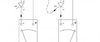
Device for checking the serviceability of a thyristor (option 3)
Rice. 3 — Diagram of a device for checking the serviceability of a thyristor (option 3)
The device (Fig. 3) is powered from an alternating current network through a step-down transformer T1. The alternating voltage of the secondary winding of the transformer is supplied to terminal X2, to which the anode terminal of the thyristor is connected. At the same time, through diode VD1, resistor R1 and push-button switch SB1, positive half-cycles of alternating voltage are supplied to the XZ terminal, to which the output of the control electrode of the SCR is connected (of course, when the switch button is pressed).
If the thyristor is working properly, it will open and lamp HL1 will light up. If the lamp lights up before pressing the button, this will indicate a defect in the thyristor - a short circuit in its control electrode circuit. If lamps HL1 and HL2 light up at the same time, then the tested thyristor is broken. None of the lamps will light in the event of another malfunction - an internal break.
Each of the resistors R2-R4 can be composed of three parallel-connected MLT-2 resistors with a resistance 3 times greater than indicated in the diagram. Diodes can be replaced with any others designed for a current of at least 300 mA. Signal lamps - for voltage 6.3 V and filament current 0.28 A (MH 6.3-0.28). Instead, you can use 26 V lamps, eliminating resistors R3, R4.
The unified vertical output transformer of TVK-110L TVs is suitable as a step-down transformer.
With a mains voltage of 220 V, its secondary winding will have a voltage of about 25 V. You can use a homemade transformer, making it on a magnetic core with a cross-section of about 5 cm2. Winding I should contain 2200 turns of PEV-1 0.2 wire, winding II - 250 turns of PEV-1 0.5.
By the way, with this probe you can test diodes designed for a current of at least 0.3 A. The anode terminal of the diode is connected to terminal X2, and the cathode terminal is connected to terminal X4. If the diode is working properly, lamp HL1 will light up (or HL2 if the polarity of the diode terminals is changed). If the diode is broken, both lamps light up, but if there is an internal break, neither of them lights up.
Verification methods
To study the deterioration of the electronic layout, it is necessary to check its components one by one.
First you need to focus on the power circuits, more specifically each of the semiconducting switches. To check the triac and thyristor, you should use one of the methods:
- multimeter;
- battery with light bulb;
- at the stand.
For research, it is necessary to disconnect the component, since during the analysis of various elements of electronic models for suitability, without removing them from the device, there is a risk of inaccurate diagnosis.
For example, say, you noticed a short circuit not of the component that is being diagnosed, but of the one associated with it in the chain synchronously.
Under any conditions, you have the opportunity to diagnose triacs and thyristors for stability without desoldering, and in case of a malfunction, remove them and do the calculations again.
Breakdown test
Testing a thyristor begins with determining the breakdown. It is recommended to start with preliminary testing, which involves measuring the resistance between the two outputs “A” and “K”, “K” and “UE”. The action algorithm has the following features:
- A multimeter is used for testing. It is turned on in the “dialing” mode, and indicators are taken between the two terminals “UE” and “K”. If the device is in good technical condition, then the readings taken will be in the range from 40 Ohms to 0.55 kOhms. A low value may indicate some problems with the device.
- Next, it is recommended to change the position of the probes, and the process is repeated. The taken indicators must correspond to those obtained in the first case.
- The next step is to measure the resistance between terminals “K” and “A”. In this case, the resistance indicator should tend to infinity. The value may vary depending on the polarity of the measuring device. A low indicator indicates that there is a breakdown in the transition. For a more accurate result, it is recommended to desolder the device being tested.
Using a multimeter
If you want to check triacs for penetration using a tester, you need to change the device system to acoustic mode.
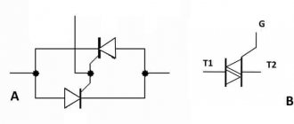
The standard location of the transceiver can be seen in the image below. A1 and A2 are electrical power terminals, thanks to which current passes to the load, and G is the main electrode.
Since the transceiver tends to vary, it is necessary to study it in the description of the triac.
In order to check a part for penetration, it is necessary to touch terminals A1 and A2 with probes; if the part is working properly, “1” or 0L will be indicated on the screen; if there is a penetration, a value close to 0.
In cases where there is no short circuit between terminals A1 and A2, it is necessary to examine the main electrode.
First, you need to touch some power terminal and the main electrode with the probes; the values should be low 80-200.
If you want to check whether a triac can open, you need to short-circuit its main electrode with one of the multimeter leads, thus applying current to it.
You can see instructions for checking using the example of a thyristor and triac below.
After removing the voltage from the main electrode, the triacs can be closed. Due to the fact that at least the smallest current must flow in order to maintain conducting conditions.
Similar properties may exist in methods that we will consider further.
Device for checking the serviceability of a thyristor (option 2)
Rice. 2 — Diagram of a device for checking the serviceability of a thyristor (option 2)
- transformer, which gives us 5-10 V output.
- diode D226, well, what was at hand. You can use any low-power one.
- electrolytic capacitor 1000 µF x 25 V.
- toggle switch (S1) to three positions, one of which is neutral (N).
- return button (S2).
- 47 ohm resistor.
- 6.3 V incandescent light bulb.
The scheme works as follows:
- We connect the thyristor T1 being tested to the wires of the circuit.
- Switch the toggle switch S1 with the neutral position to the “
", press button S2.
- The light comes on when pressed and goes out when released.
Thus, we tested the thyristor on alternating current.
- We put the toggle switch S1 in the “=” position
- We press the S2 button, the light comes on, we release the S2 button, the light still continues to light.
So we tested the thyristor at direct current.
If all operations were successful, then the thyristor is working.
Using a battery with a light bulb
In this way, you can check triacs in cases where you don’t have a multimeter, just using a light bulb. You can see the verification model for this method below.
In cases of testing a triac with a battery and a light bulb, it is necessary to remove resistor R1 from the chain. To do this, you need to use 3 alternately connected AA batteries or a crown.
In cases of assembling a portable tester according to this scheme, you have the opportunity to mount a button without focusing with the contacts shown on the model.
Provided that you are not going to make this device, you need to briefly touch the main electrode with the wire, as you already saw in the multimeter method.
Device for checking the serviceability of a thyristor (option 1)
Rice. 1 — Diagram of a device for checking the serviceability of a thyristor (option 1)
The thyristor test device (Fig. 1) is powered from an alternating current network through a step-down transformer T1. By pressing the SB1 “Control” button, the serviceability or malfunction of the thyristor is determined, in accordance with Table 1.
LED status table
| HL1 | HL2 | State |
| lit | does not burn | OK |
| lit | lit | Broken |
| does not burn | does not burn | Break |
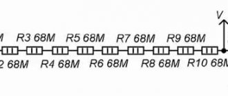
The device for testing the thyristor uses MLT resistors, and resistor R1 is made up of three MLT-2 resistors with a resistance of 150 Ohms each, connected in parallel. Low-power silicon diodes for an operating voltage of more than 30 V. Any one with a power of more than 10 W and a voltage on the secondary winding of 22...27 V is suitable as a step-down transformer.
Device for checking the serviceability of a thyristor (option 6)
The thyristor probe (Fig. 6) consists of a pulse generator on two transistors with a variable (variable resistor) duty cycle, which are fed through a diode to the control electrode of the thyristor, thereby changing its opening angle, and therefore the pass resistance, which together with resistor R7 forms adjustable voltage divider.
Rice. 6 — Diagram of a device for checking the serviceability of a thyristor (option 6)
To check, we connect the thyristor and, by rotating the variable resistor knob, observe the voltmeter readings. If the voltage changes from 0 to 10 V smoothly, then the thyristor is in working condition, if it changes abruptly or is not regulated at all, then the thyristor is faulty. You can check domestic thyristors KU101, KU112, KU201, KU202.
Source
Device for checking the serviceability of a thyristor (option 4)
Despite its simplicity, the tester (Fig. 4) allows you to test almost any popular thyristor, both low and high power, and the generator built into the circuit will help not only evaluate the operation of the semiconductor device in switch mode, but also approximately estimate its frequency characteristics.
Rice. 4 — Diagram of a device for checking the serviceability of a thyristor (option 4)
In order not to solder the thyristor, three connectors X1, X2 and X3 of any type are provided, for example, three alligator clips on flexible leads. The generator is assembled using transistors VT1 and VT2 of different conductivity; the generation frequency can be varied within 0.1 - 100 Hz by variable resistor R1. Resistor R3 serves to adjust the control voltage level, which allows you to test thyristors of any power, and therefore with different opening voltages. The normal position of the slider of this resistor is at maximum resistance (far left position).
The thyristor test is carried out in two stages. First, the thyristor is connected to the tester according to the diagram and the S1 button is pressed. A working thyristor will not light up - the breakdown test was successful. After this, the S2 button is additionally pressed, sending a signal from the generator to the control electrode. By the blinking or flickering of the lamp, the frequency of which depends on the position of the slider of resistor R1, one can judge the serviceability of the thyristor and its frequency characteristics. If the thyristor has a relatively high opening voltage, to open the device, you may have to increase this voltage by adjusting resistor R3.
Instead of the lamp indicated in the diagram, you can use any incandescent lamp with a voltage of 2.5 - 6.3 V and a current consumption of 0.1 - 0.3 A. The supply voltage can accordingly be varied within 5-10 V. It is better to use resistors R1 and R3 with a linear characteristic, for example, SP1-V or SP2-2-10, capacitor C1 - type K50-6.
Power source - any unstabilized with a voltage of 5-10 V and withstand a current of 200-300 mA.
VT1 - KT312(A-B), KT315(A-B), MP111.
VT2 - KT361(A-G), KT3107(A-F), KT502(A-B), MP25(A-B).
This device can quite successfully test thyristors KU101, 201, 221, 202, T10-160, T122-10, T15, T161, T16, T112, T222, T235 and others.