Grounding devices are current-carrying structures that provide a connection to the ground through a metal conductor. Grounding works as follows: an electric current passes through a conductor that has low resistance, creating potentials. With distance from the ground electrode the potential tends to zero. The resistance that soil provides to current flow is called “spreading resistance.” In practice, the resistance to spreading is attributed not to the soil, but to the ground electrode, and the abbreviated conventional term “ground electrode resistance” is used. In winter, when the ground freezes, and in summer, when the soil is dry, the inductive resistance is maximum while the active resistance (grounding resistance) remains constant. If the grounding device loses contact with ground, it will be energized and present a hazard. In the same way, it is dangerous if the value of the resistance of the ground electrode does not correspond to the standardized values, if there is corrosion and breaks in the ground electrode, a change in the potential difference curve is observed. In order for the grounding device to work efficiently, it is required to regularly inspect, check, test, and measure it.
Grounding concept
Grounding (Pe) is the connection of an electrical installation to a set of devices that ensure current flows into the ground.
It is divided into 2 types:
- Working. Plays the role of a neutral in the electrical circuits of powerful installations - arc arresters, arresters, transformers, generators, etc. In everyday life, a Pe system is considered to be a working system, to which a surge protection device is connected. It is customary to include grounding of lightning rods in this category.
- Protective. Prevents people from getting electrocuted. Valid only in emergency situations.
Device
The system includes:
- Ground electrode. 1 or several electrodes made of conductive material driven into the ground. In the second case, they are connected by a common bus.
- Circuit. A metal structure laid inside a building, to which electrical installations are connected directly or through a special contact in a socket. In most cases it is made of steel strip.
- Connecting bus. Provides electrical connection between the circuit and the ground electrode. Basically, it is also made from steel strip.
Grounding ensures current flows into the ground.
Principle of operation
The operation of the system is based on the ability of the soil to absorb an electrical charge like a capacitor with infinite capacity. Protective grounding involves shorting metal non-current-carrying parts of the installation to the ground - the housing (most often), fencing, etc.
If any of these elements is energized, it will remain safe for humans, because the current will flow along the path of least resistance - to the ground. And if the installation is also powered through a residual current device (RCD), then at the moment the housing contacts the live part it will be de-energized, which completely eliminates the possibility of electrical injury.
How does grounding work and why check its parameters?
Without going into details, we can say that grounding is needed to connect the electrical installation housing to the working zero. Looking at a few paragraphs above, you might think that this is absurd. In fact, what is meant is the possibility of current flowing from the protective grounding, through the physical ground (soil), to the working zero of the nearest substation. In fact, it will be a short circuit.
Accordingly, when a phase gets on the body of the electrical installation, the circuit breaker will operate, and there will be no electric shock.
Why is it necessary to check grounding resistance? To organize an emergency short circuit, a large current is required. If the resistance of the ground loop is too high, the current strength (in accordance with Ohm's law) will decrease and the circuit breaker will not operate.
Another danger of high resistance of the protective “earth” is that the resistance of the human body may be less. Then, if you touch an emergency electrical installation with your hand, you are guaranteed to be shocked by an electric shock.
Important! Grounding itself does not provide 100% protection against electric shock.
When a phase appears on the body of the electrical installation, part of the voltage will go to compensate for the leakage into the physical ground. If the remaining potential exceeds 50 volts, the danger will remain.
Likewise, a circuit breaker without grounding will not disconnect a phase if it hits the housing. It will only work when the zero is connected to the phase. Complete protection is provided by installing the machine and simultaneously connecting the protective ground circuit. The RCD also significantly increases the level of safety.
And finally, about what a ground loop is.
In short, these are several metal pins (under normal natural conditions - three), deeply immersed in the ground, connected by conductors to each other and the grounding bus in the building.
The need to check parameters
In a situation where a person touches a live body, he and the grounding conductor act as parallel-connected conductors.
The ratios of their resistances and the currents flowing through them are inversely proportional:
I1/I2 = R2/R1
The lower the grounding resistivity, the smaller the amount of charge passing through a person.
For the home electrical network, the PUE sets the following maximum permissible values (clause 1.7.97):
- with the total power of simultaneously operating electrical receivers up to 100 kVA - 10 Ohms;
- more than 100 (kVA) – 4 Ohm.
The ground electrode protrudes parallel to the conductors.
With the presence of an RCD, the reliability of the system increases. To de-energize an emergency installation, it is only necessary that the current leakage through the conductor Pe exceeds 30 mA (sensitivity threshold of the switch). But this does not affect the requirements for grounding resistivity.
The PUE specifies the parameters of other types of the Pe system:
| Device | Maximum permissible grounding resistance, Ohm |
| Lightning rod | 10 |
| Telecommunication systems | 2 |
| Server equipment | 1 |
| Working grounding of electrical installations | 4–10 |
The system resistivity Pe may increase over time.
The spread of current in the ground is prevented by:
- corrosion of the ground electrode and contacts between system components;
- dry soil;
- a change in its composition, for example a decrease in salt concentration.
Therefore, the system resistance must be checked periodically.
Effect of corrosion on grounding elements
Grounding devices: checking
Checking of grounding devices occurs after inspection - first those nodes that are in doubt are checked. Thus, ties and fastenings are checked for strength, loose bolt connections are tightened, and parts damaged by environmental influences are painted. This is the so-called cosmetic repair. It needs to be carried out regularly, and it is quite possible to carry it out by the electrical workers of the enterprise itself.
There is also a major renovation. During a major overhaul, new electrodes of grounding devices are made, as well as grounding conductors, rusted and deteriorated fasteners are replaced, and a number of other activities related to the maintenance of grounding devices are carried out. This includes drawing up and adjusting the schedule for inspection and testing of the charger, planning and training according to the plan of specialists responsible for electrical equipment, testing the knowledge of safety precautions and techniques among personnel.
Due to the fact that the resistance of the conductors themselves, and most importantly the soil, varies depending on the season, temperature and humidity, grounding devices are checked in several stages. The first is at normal humidity and average annual temperature. The second is in extreme humidity. The third is at maximum soil resistance (in winter or at the height of summer drought). As a rule, it turns out that when the ground freezes or dries out, the soil resistance turns out to be high, which actually leads to the inoperability of the grounding system in normal mode. If it is necessary to reduce the grounding resistance to normal values, you can use additional electrodes or install a new grounding circuit. To assess the condition of the charger, it is also necessary to open the soil at the grounding sites and measure the parameters of the charger itself. Regulatory document defining the sequence of operations and standardized values of the charger in operation: “Guidelines for monitoring the condition of grounding devices in electrical installations” - RD 153-34.0-20.525-00
Devices used
To measure grounding parameters, use:
- ampere and voltmeter;
- current clamps, for example brands S.A 6412, IS-20/1M, S.A 6415, S.A 6410;
- special metrological instruments of high accuracy classes based on an ohmmeter.
An ammeter is used to measure grounding parameters.
Classic representatives of the latter group are analog devices of the following brands:
- ISZ-2016;
- MS-08;
- F4103-M1;
- M-416.
Modern digital models with a processor, a function for storing measurement results, etc. are more accurate and easier to use.
Taking measurements
And yet, in the question of how to measure grounding resistance, it is better to use a megohmmeter rather than a multimeter. The best option is considered to be a portable electrical measuring device M-416. Its operation is based on the compensation measurement method; for this purpose, a potential electrode and an auxiliary ground electrode are used. Its measuring limits are from 0.1 to 1000 Ohms, the device can be operated at temperatures from -25 to +60 degrees, power is provided by three 1.5 V batteries.
And now step-by-step instructions for the entire process on how to measure the resistance of the ground loop:
- Place the device on a horizontal, flat surface.
- Now calibrate it. Select the “control” mode, press the red button and, while holding it, set the arrow to the “zero” position.
- There is also some resistance in the connecting wires between the terminals; to minimize this influence, place the device closer to the ground electrode being measured.
- Select the desired connection diagram. You can check the resistance roughly; to do this, connect the terminals with jumpers and connect the device using a three-terminal circuit. For accurate measurements, the error caused by the connecting wires should be eliminated, that is, the jumper is removed between the terminals and a four-clamp connection diagram is used (by the way, it is drawn on the cover of the device).
- Drive the auxiliary electrode and probe rod into the ground to a depth of at least 0.5 m, keep in mind that the soil must be dense and not bulky. To hammer in, use a sledgehammer, the blows should be straight, without swinging.
- Clean the place where you will connect the conductors to the ground electrode with a file to remove paint. Use copper conductors with a cross section of 1.5 mm2 as conductors. If you use a three-clamp circuit, then the file will act as a connecting probe between the ground electrode and the terminal, since a copper wire with a cross-section of 2.5 mm2 is connected on its other side.
- And now we move on directly to how to measure grounding resistance. Select the range “x1” (that is, multiply by “1”). Press the red button and turn the knob to set the arrow to zero. For larger resistances, it will be necessary to select a larger range (“x5” or “x20”). Since we chose the “x1” range, the number on the scale will correspond to the measured resistance.
It is clear how grounding is measured in the following video:
Basic rules and techniques for measuring grounding
All methods for assessing the state of a system are based on Ohm's law for a section of a circuit. Knowing the voltage U of the source to which the ground is connected, measure the current I flowing in it and calculate the resistance using the formula:
R = U/I
The following methods are used:
- Ampere and voltmeter. The simplest, but also the least accurate. 2 electrodes are driven into the ground 20 m from the ground electrode and connected to a calibrated voltage source. Then the current strength is determined with an ammeter, and the potential drop in the area of interest is determined with a voltmeter and calculations are made.
- Compensating 3-wire. Involves the use of special meters such as M-416. 2 electrodes are also driven into the ground, but on both sides of the ground electrode, then the device is connected to them. There is no need to make calculations - the system resistivity Pe is read on the scale. The device also allows you to measure soil resistivity. To do this, use the 4-wire method.
- Using 2 current clamps. Measure the background current from the electrical installation to the ground. The method allows you to do without additional electrodes and disconnecting the Pe circuit, i.e. chain break.
Grounding measurement techniques are based on Ohm's law.
The choice of method depends on the operating conditions of the equipment.
Technology for working with the M-416 device
Work with the meter begins with calibration:
- Place it on a flat horizontal surface.
- Set the range switch to the “Control” position.
- Press the red button and rotate the slider handle so that the arrow points to “0”.
The scale of a working device will display “5 Ohms”. The permissible deviation is 0.3 in both directions.
Then proceed in this order:
- De-energize the network in the building or disconnect the Pe conductor from the installation.
- The clamp is connected to the device with a cable.
- Drive 2 electrodes into the ground. Minimum depth – 50 cm.
- Clean the junction of the bus and the ground loop from paint and rust.
- Connect the electrodes and ground electrode (using a clamp) to the device in accordance with the diagram shown on the inside of the cover.
- Set the range switch to the desired position. For example, for resistances up to 10 Ohms - “x1”.
- Rotate the slider knob to set the arrow to “0”.
- Take readings from the scale and multiply by the number to which the range switch is set.
- In the same way, several more measurements are taken to check, slightly changing the position of the electrodes.
To begin work, de-energize the network in the building and disconnect the conductor.
The procedure is completed correctly if all results differ from one another by no more than 5%.
Measurements are carried out in summer in stable dry weather, when the soil has maximum resistance.
ELECTROlaboratory
1.
Introductory part.
1.1.Purpose
of the work being carried out and in accordance with
RD 153-34.0-20.525-00 is to determine the compliance of the characteristics of the grounding device (GD) with the requirements for ensuring the electrical safety of operating personnel and ensuring the following operational functions of the electrical installation under normal and emergency conditions:
· operation of relay protection against ground faults;
· operation of surge protection;
· diversion of lightning currents into the ground;
· removal of operating currents (unbalance currents, etc.);
· protection of insulation of low-voltage circuits and equipment;
· reduction of electromagnetic influences on secondary circuits;
· protection of underground equipment and communications from current overloads;
· stabilization of potentials relative to the ground and protection against static electricity;
· ensuring explosion and fire safety.
1.2. Scope and standards of testing
The chargers are installed
RD 34.45-51.300-97 :
· checking the elements of the grounding device;
· measurement of resistance of grounding devices.
1.3.Terms and definitions.
Grounding
is
an intentional electrical connection of any point in the network, electrical installation or equipment with a grounding device
.
Working (functional) grounding
— grounding of a point or points of live parts of an electrical installation, performed to ensure the operation of the electrical installation (not for electrical safety purposes).
Protected grounding _ _ _ _ _
in electrical installations with voltage up to 1 kV - deliberate connection of open conductive parts with a solidly grounded neutral of a generator or transformer in three-phase current networks, with a solidly grounded output of a single-phase current source, with a grounded source point in direct current networks, performed for electrical safety purposes.
Grounding is used to set and maintain the potential of a connected circuit or equipment as close to ground potential as possible. A ground circuit is formed by a conductor, a clamp or connection by which the conductor is connected to an electrode, the electrode, and the ground around the electrode. The ground electrode or grounding device may be connected to the main ground bus.
Main ground bus
- a bus that is part of the grounding device of an electrical installation up to 1 kV and is intended for connecting several conductors for the purpose of grounding and potential equalization.
Potential equalization
- electrical connection of conductive parts to achieve equality of their potentials.
Protective potential equalization
— potential equalization performed for electrical safety purposes.
Grounding is widely used for the purpose of electrical protection in case of damage to the insulation of electrical equipment.
The low resistance of the grounding circuit ensures that the breakdown current flows to the ground and
triggering of protective devices. As a result, extraneous voltage is removed as quickly as possible to avoid exposing personnel and equipment to it.
To best fix the support
potential of the equipment in order to protect it from static electricity and limit the voltage level on the equipment body to protect personnel, the ideal resistance of the grounding circuit should be zero, which in reality is not possible, since this resistance depends on many factors.
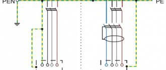
Figure 1 shows the grounding pin as an integral part of the grounding loop. Its resistance is determined by the following components:
a) the resistance of the metal of the pin and the resistance of the contact of the conductor with the pin;
b) contact resistance of the pin with the ground;
c) resistance of the earth's surface to flowing current, in other words, earth resistance, which is often the most important of the listed terms.
Typically, the grounding pin is made of a highly conductive metal (a metal electrode from a corner or pipe without any coating, as well as electrodes made of copper) and a terminal of appropriate quality (most often, instead of a terminal, connections are made by welding), so the resistance of the pin and its contact with the conductor can be neglected.
The contact resistance of the electrode with the ground can be neglected if the electrode is dense
but it is hammered in and there is no paint, oil or similar substances on its surface.
The last component left is soil resistance. One can imagine that the electrode is surrounded by concentric layers of soil of equal thickness. The layer closest to the electrode has the smallest surface area but the greatest resistance. As you move away from the electrode, the surface of the layer increases and its resistance decreases. Ultimately, the contribution of the resistance of remote layers to the resistance of the soil surface becomes insignificant. The region beyond which the resistance of the earth's layers can be neglected is called the region of effective resistance. Its size depends on the depth of immersion of the electrode into the ground.
1.4.
Test and measurement object
.
The objects of testing and measurements carried out according to this method are: grounding devices (grounding conductors in the case of using single electrodes), potential equalization conductors (with the exception of PE and PEN conductors, which are included in the cable as a separate core), the main grounding bus and soil in the area where grounding devices are installed.
The following are used as artificial grounding conductors:
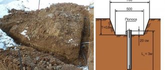
Deep grounding conductors - strips or round steel laid horizontally at the bottom of a pit or trench in the form of extended elements;
Vertical grounding electrodes - steel screw-in or drive-in rods with a diameter of 12-16 millimeters, angle steel with a wall thickness of at least 4 millimeters or steel pipes (substandard with a wall thickness of at least 3.5 millimeters) The length of the screw-in electrodes is usually 4.5-5 meters, hammered corners and pipes 2.5-3 meters
The upper end of the vertical electrode should be at a distance of 0.6-0.7 meters from the surface of the earth (Figure 2). The distance from one electrode to another must be no less than its length.
Horizontal grounding conductors are steel strips with a thickness of at least 4 millimeters or round steel with a diameter of at least 10 millimeters. These grounding conductors are used to connect vertical grounding conductors and as independent grounding conductors.
Electrodes and grounding conductors must not be painted and must be free of rust, traces of oil, etc. In welding areas, the metal is protected from corrosion using varnish coatings.
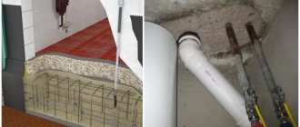
Metal parts of buildings must be combined into a single unit to create a common grounding loop. The connection must be made by welding. The common kennel of the building is connected to the ground electrode by two separate conductors.
Inside the building, the connection of the ground loop with the equipment that is being grounded.
The connection of the equipment to the grounding line inside the building is carried out using a separate conductor, the cross-section of which must be equal to the cross-section of the phase conductor of the wire or cable used to power this electrical equipment and, in addition, comply with the conditions given in Table 1. The minimum cross-section of the grounding conductor inside the building is 2 .5 millimeters square for copper, provided that the protective conductor is not part of the cable and has protection from mechanical damage and 4 millimeters if there is no such protection.
Table 1
| Section of phase conductors, (mm2) | Smallest cross-section of protective conductors, (mm2) |
| S ≤ 16 16 < S ≤ 35 S > 35 | S 16 S /2 |
When using grounding conductors for the purposes of lightning protection or protection against static electricity and at the same time for protective grounding of electrical equipment, the use of foreign metal and reinforced concrete structures is not allowed. For these purposes, it is necessary to use special grounding conductors.
Parts to be grounded must be connected to the grounding device with a separate conductor. Series connection of parts to be grounded into the grounding conductor is not allowed.
The equipment must have special bolts or metal plates for connecting grounding conductors, which must be marked in accordance with GOST 21130-75.
Installation or mounting bolts must not be used to connect grounding conductors.
2.
Measuring instruments and requirements for them.
2.1. The quality of the equipment assessment, the correctness of the conclusion about its suitability for use and the reliability of its operation depend on the correct choice of the measurement method and measuring instrument.
Measurement methods are divided into direct and indirect. In practice, measurements are most often made by direct assessment using a pre-calibrated instrument or by comparison. Both methods are classified as direct measurements. Their popularity is associated with greater simplicity and, most importantly, with the greatest accuracy, primarily of the comparison method in relation to indirect measurements.
2.2. When measuring the charger resistance and soil resistivity, the M-416 grounding resistance meter with set F and the MPI-511 electrical installation parameters meter are used. Although other devices can be used
2.3. Metrological characteristics of the above-mentioned devices, copies of certificates for compliance with their specified types and the right to operate on the territory of the Russian Federation, as well as the rules for their operation and safety during their use are given in copies of factory passports. Copies are attached.
2.4. All measuring instruments used by ETL MP "Vodokanal of the city of Ryazan" undergo regular verification at the Federal State Institution "Ryazan CSM" according to a schedule drawn up on the basis of the passport data of the measuring instruments.
3.
Conditions for carrying out measurements and tests.
3.1. Measurement of the resistance of grounding devices according to PTEEP is carried out at the moment of maximum drying of the soil. In permafrost zones, measurements are made at the moment of maximum soil freezing.
The previous condition is not always feasible, especially when conducting acceptance tests. In this case, RD153-34.0-20.525-00 recommends using the seasonal coefficient K
With.
The resistance R
of the charger is determined by the formula
R
Memory =
K
s ×
R
Memory meas.
where R
Charger meas — charger resistance obtained during measurements.
3.2. Atmospheric pressure does not have a special impact on the quality of the tests, but is recorded for recording data in the protocol.
4.
Safety rules for measurements and tests.
Work on measuring the characteristics of the charger must be carried out in accordance with the current Safety Rules for the operation of electrical installations. Work on measuring electrical characteristics should be carried out according to work orders.
The size of the team must be at least two people: a work supervisor with an electrical safety group of at least IV and a team member with an electrical safety group of at least III when measuring in existing switchgears (RU) with voltages above 1000V or a work supervisor with an electrical safety group of III and a member of a team with Group II for electrical safety during measurements in switchgear with voltages up to 1000V, as well as before connecting electrical installations to the power supply network.
When making measurements at operating power facilities using remote current and potential electrodes, measures must be taken to protect against the effects of full voltage on the ground electrode when a single-phase short-circuit current flows from it to the ground.
Personnel performing measurements must work in dielectric boots, dielectric gloves, and use tools with insulated handles.
When assembling measuring circuits, you should first connect the wire to the auxiliary electrode (current, potential) and only then to the corresponding measuring device.
5.
The procedure for preparing for measurements.
When carrying out activities to prepare for measurements, the following work should be performed:
· determine the scope of a specific test since tests are divided into acceptance tests; tests during major repairs and current repairs. The frequency of tests is regulated in PTEEP App. 3. clause 26 (See table 2)
Table 2.
TEST STANDARDS FOR GROUNDING DEVICES
| Test name | Type of test | Test standards | Directions |
| 26.3. Checking the condition of the grounding device elements located in the ground: | M | The corrosion condition is checked at least once every 12 years. The grounding element must be replaced if more than 50% of its cross-section is destroyed | |
| 1) electrical installations, except overhead lines | Checking of grounding conductors in outdoor switchgear of power plants and substations is carried out selectively, in places most susceptible to corrosion, as well as near the grounding points of power transformer neutrals, connections of arresters and surge suppressors | In the closed switchgear, inspection of grounding elements is carried out by decision of the technical manager of the Consumer | |
| 2) VL | On overhead lines, a random check with opening of the soil is carried out on at least 2% of the supports of the total number of supports with grounding conductors | The check should be carried out in populated areas, in areas with the most aggressive, blown and poorly conductive soils | |
| 26.4. Measuring the resistance of grounding devices: | |||
| 1) supports of overhead power lines | K, T, M | The resistance values of the support grounding conductors are given in Table 35 (Appendix 3.1) | Produced after repairs, but at least once every 6 years for overhead lines with voltages up to 1000V and 12 years for overhead lines above 1000V on supports with arresters and other electrical equipment and selectively on 2% of metal and reinforced concrete supports in areas in populated areas. Measurements are also carried out after reconstruction and repair of grounding devices, as well as when destruction or traces of overlapping of insulators by an electric arc are detected |
| 2) electrical installations, except overhead power lines | K, T, M | The resistance values of grounding devices of electrical installations are given in Table 36 (Appendix 3.1) |
Note:
1.K,T,M - are carried out within the time limits established by the PPR system, taking into account the instructions of clauses 26.1...26.4, but T at least once every 3 years according to
GOST R50571.16-2007.
2. checking the condition of lightning protection devices - once a year before the start of the thunderstorm season;
· using the memory passport, determine the geometric dimensions of the grounding conductors that affect the arrangement of the electrodes of the measuring instrument.
· create diagrams of the location of the electrodes of the auxiliary ground electrode and the probe relative to the ground electrode being tested
Fig.3. Connecting the M-416 device using a three-clamp circuit to a single ground electrode.
Fig.4. Connecting the M-416 device using a four-clamp circuit to a single ground electrode.
Fig.5. Connecting the M-416 device using a three-clamp circuit to a complex (circuit) grounding electrode
Fig.6. Connecting the M-416 device using a four-clamp circuit to a complex (circuit) grounding electrode.
Prepare the device for measurements:
Place the device on a flat surface and open the lid;
set the switch to the “5 Ohm Control” position, press the button and rotate the “Reochord” knob until the indicator needle is set to zero. The scale should show a reading of 5±0.3 Ohm under normal climatic conditions and normal power source voltage. Normal supply voltage is from 3.8V to 4.8V.
In diagrams Fig. 3 and 5, the resistance of the connecting wires is added to the resistance of the ground electrode being measured, which makes the measurement less accurate and is acceptable when measuring resistances of more than 1 Ohm. In diagrams Fig. 4 and 6, the resistance of the connecting wires is compensated and the measurement is more accurate. d in these diagrams is the largest diagonal of the contour of the grounding device being measured in meters.
6. Procedure for testing and measurements.
When conducting tests before putting the charger into operation, it is necessary to follow the order given in the PUE, Chapter 1.8, Section 1.8.39
6.1. Checking the elements of the grounding device.
The check should be carried out by inspecting the elements of the grounding device within the scope of inspection. The cross-sections and conductivities of the elements of the grounding device, including the main grounding bus, must comply with the requirements of PUE Chapter 1.7 and design data.
6.2. Measuring the resistance of grounding devices.
The resistance values of grounding devices with connected natural grounding conductors must satisfy the values given in the relevant chapters of the PUE and Table 5.
Table 5
The highest permissible resistance values of grounding devices
| Type of electrical installation | Characteristics of the electrical installation | Resistance, Ohm |
| 1. Substations and distribution points with voltage above 1 kV | Electrical installations of electrical networks with solidly grounded and effectively grounded neutral. | 0,5 |
| Electrical installations of electrical networks with an isolated neutral, with the neutral grounded through an arc suppression reactor or resistor. | 250/ Ip * | |
| 2. Overhead power lines with voltage above 1 kV | Grounding devices for overhead line supports (see also 2.5.129-2.5.131) with soil resistivity, r, Ohm m: | |
| - up to 100 | 10 | |
| — more than 100 to 500 | 15 | |
| — more than 500 to 1000 | 20 | |
| — more than 1000 to 5000 | 30 | |
| — more than 5000 | r·6 10—3 | |
| Grounding devices for overhead line supports with arresters at the approaches to switchgears with rotating machines | see chapter 4.2 | |
| 3. Electrical installations with voltage up to 1 kV | Electrical installations with power supplies in electrical networks with a solidly grounded neutral (or midpoint) of the power source (TN system): | |
| - in close proximity to neutral | 15/30/60** | |
| — taking into account natural grounding and repeated grounding of outgoing lines | 2/4/8** | |
| Electrical installations in electrical networks with an isolated neutral (or midpoint) of the power source (IT system) | 50/ I ***, more than 4 required | |
| 4. Overhead power lines with voltage up to 1 kV | Grounding devices for overhead line supports with repeated grounding switches PEN (PE) - conductors | 30 |
I
p*—estimated ground fault current;
** - respectively at linear voltages 660, 280, 220 V;
I
*** - total ground fault current.
When carrying out tests after current or major repairs, it is necessary to use the procedure given in Table 2. The standardized values of the parameters of grounding devices in this case are defined in PTEEP Appendix 3.1, Table 35 and 36.
Fig. 7 Circuit for measuring charger resistance
6.2.1
Measuring charger resistance using the M-416 device.
The operating principle of the device is based on comparing the potential difference across the measured resistance and the reference one. At the moment of equality of the compared voltages, the current in the indicator circuit will be zero. The device is equipped with a scale that allows you to directly determine the value of the measured resistance.
The device can measure using either a three-clamp circuit (Fig. 7, measuring resistances over 50 Ohms) or a four-clamp circuit (in this case, the jumper between terminals 1 and 2 is removed, and two conductors go to the probe connected to the charger from terminal 1 and terminal 2 , due to which the influence of the resistance of the connecting wires when carrying out measurements is compensated for less than 50 Ohms).
When measuring using a single-beam scheme (Fig. 3), the distance from the ground electrode to the probe (R3) must be at least 5D + 20 m, where D is the largest diagonal of a complex ground electrode (for a simple ground electrode D = 0), and from the probe to the auxiliary electrode no less 20m for a complex grounding conductor and 10m for a simple one.
The resistance of the auxiliary grounding electrode and probe is important for the accuracy of measurements, namely, the main error of the device remains within the limits of the passport data with the resistance of the auxiliary grounding electrode and probe not exceeding:
500 Ohm in the measurement range 0.1 – 10 Ohm;
1000 Ohm - 0.5 - 50 Ohm;
2500 Ohm - 2 - 200 Ohm;
5000 Ohm - 10 - 1000 Ohm.
The resistance of the electrodes is measured according to the diagram in Fig. 6 with the following changes: a jumper is placed between terminals 3 and 4, the probe touching the charger is connected to terminal 2, and one of the electrodes (for example, first the probe) is connected to terminal 3 and a measurement is taken, then to the terminal 3, the auxiliary grounding conductor is connected and the measurement is carried out.
If the resistance of the electrodes is greater than the above, it must be reduced by moistening the soil at the place where they are driven in, or use several interconnected electrodes instead of one.
The measurement procedure is as follows:
Set the switch to the “5 Ohm Control” position, press the button and rotate the “reochord” knob until the indicator needle is set to zero, the scale should read 5±0.3 Ohm;
Assemble a measurement scheme;
Set the range switch to “x1”, press the button and rotate the reachord to set the arrow to zero.
If the measured resistance is greater than 10 ohms, select a different range.
Metal rods with a diameter of 10-12 mm and a length of 1.2 meters, immersed in the ground to a depth of at least 0.5 meters, are used as electrodes.
6.2.2 Measurement of soil resistivity.
Figure 8. Circuit for measuring soil resistivity using the four-electrode method.
Measurement of soil resistivity is carried out when the measured resistance of the ground electrode is greater than the design (calculated) value or does not meet regulatory requirements.
In this case, the permissible degree of this discrepancy is checked at increased soil resistivities.
Measurements are carried out using the “vertical sounding” method.
Electrodes A, M, N and B are installed at equal distances from each other. It is advisable to make several measurements changing the distance between the electrodes.
Soil resistivity is calculated using the formula:
ρ = k·Rmeas,
where k is a coefficient depending on the distance between the electrodes, which is determined by the formula:
k = 2πа,
where a is the distance between the electrodes, which should be taken at least 5 times the immersion depth of the electrodes (m).
6.2.3.
Measuring the resistance of the charger using the M PI -511 device.
To measure grounding resistance with the MPI-511 device, the phase wire of the network is used as an additional voltage source to create the measuring current. To eliminate the influence of the resistance of the working ground, source and phase wire, an additional electrode is used, driven into the ground (comparative ground) and connected to socket S - Fig. 9.
Before measuring ground resistance, it is necessary to become familiar with the grounding system of the network and electrical equipment.
When measuring in a TN-C, TN-CS network, using a phase of the same network, it is necessary to disconnect the conductor PE, N from the ground electrode being measured (Fig. 9. b)
Please note
: Disconnecting the conductors of the grounding device creates a serious danger for the persons performing measurements and bystanders. At the end of the measurements, it is necessary to restore a reliable connection of the protective, neutral conductor.
Fig.9. Method of connecting the MPI-511 meter when measuring ground resistance: a) for TN-S and TT networks, b) for TN-C, TN-CS networks.
To measure ground resistance you need:
· set the rotary function switch to position RE;
·connect the measuring leads in accordance with Fig. 9; wire L can be of any length;
·wire WS-01 is used to measure the grounding resistance of the PE circuit in the network socket;
READY appears on the left side
, press the “start” key.
Fig. 10. Displaying information on the display when measuring ground resistance
Inscription READY
indicates that the voltage at the meter terminals is within the range for which measurements can be made. Otherwise, L-PE appears. On the right side, the voltage and frequency of the measured circuit are displayed.
A detailed description of the operation of the MPI-511 device is attached. (See a copy of the passport and operating instructions for the MPI-511 device).
7. Processing of measurement results.
During testing, the results are recorded in a special workbook or in the memory of the MPI-511 device, strictly following the list of equipment being tested.
At the end of the measurements, it is necessary to determine the error of each measurement and, taking into account its worst result from the results area, determined by the measurement error, record it in the form corresponding to the type of test.
The following is the procedure for determining the error for each of the instruments used in this technique.
7.1.1.
General procedure for determining measurement error
.
The measurement accuracy depends on the measurement method and the accuracy class of the selected measuring instruments. The accuracy class of a measuring instrument is determined by its error.
Absolute error
instrument - the difference between the instrument readings Apr and the actual value of the measured value Ad:
∆A=Apr-Ad.
Absolute measurement error:
δA= -∆A.
Actual value of the measured variable:
Ad=Apr+δA.
Relative error of the device
ε,% is determined by the ratio of the absolute error of the device to the actual value of the measured quantity:
ε = (∆A/Ad) 100 = ((Apr-Ad)/Ad) 100.
To determine the accuracy class of the device, the reduced relative error
– the ratio of the absolute error to the upper limit of measurement of the device Amax,%,
ε0 = (∆A/Amax) 100.
Permissible reduced relative error of a device – the largest reduced relative error permissible for a given device, %
εadd=(∆Аmax/Аmax) 100.
The permissible reduced relative error determines the accuracy class of the device indicated on its scale.
The accuracy of the device is guaranteed by the manufacturer under certain conditions (temperature, electromagnetic influences, overloads, current frequency, etc.). The influencing factors are indicated in the data sheet for the measuring instrument.
The greatest relative error of an individual measurement carried out in a direct way is determined by the permissible relative error of the device:
εA = ± εadd (Amax/Apr).
Therefore, to reduce measurement error, it is recommended to choose a device with such measurement limits that the reading is made in the upper half of the scale.
Based on the above, the relative measurement error in the general case is determined by:
ε =√(εА2+Σεi2),
where εi is the relative measurement error due to the i-th external factor.
In practice, it is difficult and unnecessary to take into account all the values of relative errors. Based on this, the relative error of the device and the main errors caused by the measurement conditions are taken into account:
ε =√(εA2+εns2 + εhor2 + εt2),
where εns is the error caused by the instability of the instrument readings in steady state;
εhor – error caused by the deviation of the device from the horizontal position, taken into account when carrying out measurements with analog instruments;
εt – error due to temperature measurement conditions.
Based on the operating principle of some devices, their main reduced error can be determined using the original formula. In these cases, the formula for determining the error is indicated in the device passport.
By analyzing the last expression, you can determine the rules for working with electrical measuring instruments in which the measurement error will be minimal, and therefore the measurement result will be as close as possible to the actual one:
· the device must be in good working order and verified by the relevant organization;
· analog instruments when carrying out measurements must be placed on a horizontal rigid base (with the exception of instruments with a vertical working position);
· when using multi-limit instruments, it is necessary to select measurement limits that are as close as possible to the values of the measured quantities;
· read the instrument readings at an angle of 90° (when using a device with a mirror scale, the instrument needle must be aligned with its reflection);
· do not place devices on surfaces and bases subject to vibrations and fluctuations;
· make measurements only after aligning the instrument needle with the zero scale mark.
It should also be noted that when using digital instruments, the measurement error is determined by the expression:
δп ± n,
where δп is a constant component of the relative error over the entire measurement range;
n – number of units of device resolution.
This entry is not correct, because represents the algebraic sum of relative and absolute units. To determine the measurement error, it is necessary to switch to one type of units.
7.1.2.
Methodology for calculating the error of the MPI -511 device.
The technique is described in detail in GOST R IEC 61557-5-2008.
Table 6.
Measuring range RE according to IEC 61557-5: 0.3 …
1999 Ohm
| Range | Permission | Basic error |
| 0.00…19.99 Ohm | 0.01 Ohm | ±(5% RE + 5 emr) |
| 20.0…199.9 Ohm | 0.1 ohm | ±(5% RE + 5 emr) |
| 200…1999 Ohm | 1 ohm | ±(5% RE + 5 emr) |
· Rated voltage of the network used as an additional source Un: 115, 220, 230, 240 V (100...250 V);
· Rated frequency of additional network fn: 50, 60 Hz (45…65 Hz);
· Maximum measurement current (for Un=230 V): 23 A (10 ms).
Table 7.
Determination of the error of measuring equipment under operating conditions of use
— resistance of probes and auxiliary grounding electrodes 100 Ohm;
— interference voltage 0V.
7.1.3. Methodology for calculating the error of the M-416 device.
δo= ±(5+(N/RX – 1)),%.
where δo is the main error;
N – final value of the range, Ohm;
RX – measured resistance, Ohm.
The value of the main error corresponds to the above formula with the resistance of the auxiliary ground electrode and probe no more than:
500 Ohm in the range 0.1 – 10 Ohm;
1000 Ohm in the range 0.5 – 50 Ohm;
2500 Ohm in the range 2 – 200 Ohm;
5000 Ohm in the range 10 – 1000 Ohm.
Therefore, when measuring the resistance of the grounding device, it is necessary to measure the resistance of the auxiliary grounding electrode and the probe.
The additional error caused by the influence of stray currents with a frequency of 50 Hz does not exceed half of the main error.
Having thus determined the ranges of values in which our measurement results fall, we fill out the protocol. By comparing the results obtained with the standardized values, we draw a conclusion about the compliance or non-compliance of the results obtained with the requirements of standards or design documentation.
A copy of the protocol form is attached.
8. Normative literature.
1) PUE ed. 7. Novosibirsk Siberian University Publishing House 2007
2) Rules for the technical operation of consumer electrical installations (PTEEP) M.OMEGA-L 2006.
3) Interindustry rules on labor protection (safety rules) for the operation of electrical installations. POT RM-016-2001. RD 153-34.0-03.150-00, M.OMEGA-L 2006
4) GOST R50571.16-2007 Low-voltage electrical installations. Part 6. Tests. M. Gosstandart of Russia
5) GOST R50571.10-96. Electrical installations of buildings. Part 5. Selection and installation of electrical equipment Chapter 54. Grounding devices and protective wiring.
6) GOST 12.3.019-80. Electrical tests and measurements General safety requirements. M., Standards Publishing House, 1987.
7) RD 153-34.0-20.525-00. Guidelines for monitoring the condition of grounding devices in electrical installations.
 RD 34.45-51.300-97. Scope and standards for testing electrical equipment.
9) GOST R IEC 61557-1-2006. Low-voltage electrical distribution networks with voltages up to 1000 V AC and 1500 V DC. Electrical safety. Equipment for testing, measuring or monitoring protective equipment.
10) GOST R IEC 61557-5-2008. Low-voltage electrical distribution networks with voltages up to 1000 V AC and 1500 V DC. Electrical safety. Equipment for testing, measuring or monitoring protective equipment. Part 5. Resistance of the ground electrode relative to the ground.
You can purchase a complete set of methods for measuring and testing electrical equipment up to 1000V on the next page;
LINK
The nuances of checking grounding in sockets
The presence of a Pe connection can be checked with available tools, without the help of professionals. Several methods are used.
Multimeter
Switch the device to the alternating voltage (AC) measurement mode of approximately ~220 V.
Then proceed in the following order:
- Using an indicator screwdriver, determine which terminal of the socket the “phase” is connected to (the light on the indicator will light up).
- Measure the voltage between this contact and “zero” with a multimeter.
- Disconnect the instrument probe from the neutral. Touch it to the ground terminal and take readings again.
The following situations are possible:
- The measurement results in step 3 are the same as in step 2 or a little less - the grounding is working properly.
- There is a significant difference in the readings - the Pe system has extremely high resistance.
- In step 3, the device showed “0” - there is no contact with ground.
The multimeter is switched to AC voltage measurement mode.
Indicator light
Create a makeshift tester:
- screw the light bulb into the socket;
- Solder a piece of copper wire to its contacts.
Touch the “phase” terminal with one “probe” and the ground terminal with the other.
The following situations are possible:
- The light is bright - the Pe system is working.
- The light is dim – there is contact, but the system resistivity is extremely high.
- Off – Pe is missing.
If an indicator screwdriver is not available, apply one probe to the Pe terminal, and use the others to check the remaining two in turn.
Make a makeshift tester out of a light bulb.
If the light does not light in both cases, check the functionality of the socket.
To do this, the wires touch the terminals to which the “phase” and “zero” are connected.
Indirect evidence of the absence of Re
The following signs indicate grounding failure:
- water heater, washing machine or dishwasher electrocutes;
- When playing music, the speakers make extraneous noise.
Testing with a digital voltmeter
You need a device to measure alternating (AC) voltage. Pointer models are analog and do not require power.
Digital ones operate on rechargeable batteries or batteries and have the following advantages:
- data is displayed on the display, which makes it easier to read and increases the accuracy of measurements;
- the performance of the device does not depend on orientation in space;
- measurement results are stored in memory.
Digital voltmeters operate on batteries.
The switch is set to a range that includes 220 V. When using a pointer device, the wires from the probes are screwed to the corresponding contacts. Next, check in the same way as with a multimeter.
2.7. Checking the condition of blow-out fuses
Checking the condition of blow-out fuses involves checking the integrity of the porcelain, threaded connections and fastenings, and the quality of grounding. The discharge surfaces of the electrodes must be clean and smooth, without burrs and deposits. The mica plate must be intact and have a thickness within 0.08±0.02 mm
when performing at 220-380
V
and 0.21±0.03
mm when
performing at 500-660
V.
The insulation resistance of the assembled fuse is measured with a megohmmeter up to 250 V
, which must be at least 5
MOhm
.
Before installing a fuse, its breakdown voltage is measured. The main values of breakdown voltages of PP-A/3 fuses are given in table. 3.
Table 3
| Rated mains voltage, V | Execution | Breakdown voltage, V | Thickness of mica spacer, mm |
| 220-380 500-660 | I II | 351-500 701-1000 | 0,08±0,02 0,21±0,03 |
kOhm is included in the fuse circuit
.
If the breakdown voltage is normal, the voltage decreases and increases again to 0.75 U
samples If breakdown does not occur, the test setup is switched off and the insulation resistance is re-measured. If the insulation resistance decreases significantly (more than 30%), it is necessary to disassemble the fuse, clean the burnt discharge surfaces and repeat the tests, increasing the ballast resistance.
Testing in an apartment or private house yourself
The scope of work to check Pe in a city apartment and a cottage is different.
In the first case, perform the following actions:
- Check the functionality of the outlet by plugging in a table lamp or other known working device.
- They cut off power to the apartment.
- Remove the decorative panel from the socket and look at how many cores are in the supplied wire and how the Pe terminal is connected.
The cable must have 3 cores. It is customary to connect the Pe terminal to the one with yellow-green insulation.
If a visual inspection confirms the presence of grounding, return the decorative panel to its place, apply power to the network and check the Pe system using any of the described methods.
In a city apartment, the functionality of the outlet is checked.
The owner of a private house needs to additionally check the resistance value of the ground electrode. To do this, call specialists with the appropriate equipment.
It is better to use a megohmmeter to assess other safety factors
For example, insulation resistance. We are not talking about direct danger. That is, if you grab a wire with your hand in which the dielectric properties of the insulation are normal, you will not receive an electric shock.
But there is an additional danger: insulation breakdown under load. This unpleasant fact leads to malfunctions and, what’s more scary, to electrical circuit fires.
A megohmmeter for measuring insulation resistance is a voltage generator and a precision instrument in one housing.
The classic version (still used successfully today) produces voltage up to 2500 volts. Don't be afraid, the currents during operation are negligible. But you only need to hold on to the insulated handles of the measuring cables.
The high voltage potential easily reveals flaws in the insulation, and the meter needle shows the true resistance. Before starting work, you should turn off all voltage-supplying circuit breakers and get rid of residual potential: ground the wire.
To measure the breakdown between wires in one cable, two wires are used. They are connected to the cores of the disconnected cable, and measurements are taken. If the resistance is below normal, the cable is rejected. No one knows when a potential breakdown site will cause trouble.
To measure earth leakage, one wire is connected to the protective ground (in the area where the cable under test is laid), and the second to the central core. The voltage for testing should be higher. If the wire cannot be connected to ground, the measurement is carried out by applying a second electrode to the outer surface of the insulation.
If there is a screen (cable armor), a three-wire measurement system is used. the third wire is connected to the shield of the cable being tested.
The general scheme is exactly this, but each model of the device has its own instructions. Modern megohmmeters with a digital display are even easier to understand than the old pointer meters.
Using a megohmmeter, you can also test motor windings. But this is a separate topic. Information for those who think that all these devices are narrow-profile: using a shunt system, you can turn a megaohmmeter into a precision ohmmeter or voltmeter.
Solving connection problems
If checking Pe shows that it is not working, do the following:
- Check the functioning of the network by plugging any device into the outlet.
- If it works, remove the plug and de-energize the apartment using the machine in the panel.
- Disassemble the socket and check the connection of the wires to the terminals.
If the contact is broken due to a broken conductor, the connection is restored. If there is no visible damage, call an electrician.
Measurement principle
The resistance of grounding devices is measured at intervals established by the enterprise, but at least once every 12 years. For more accurate measurements, an artificial electrical network is created.
An auxiliary device, called a current electrode, is built into the ground next to the circuit under test, and it is also connected to the network. They also install an electrode, which is used to determine the voltage drop in the network.
In order to measure and obtain more reliable data, there must be optimal weather conditions at the time the process is carried out. That is, the soil resistance at this moment should be maximum. In this case, the following conditions must be met:
the electrode from which readings will be taken is placed strictly between the grounding structure and the additional electrode; the distance between the elements should be equal to five times the depth of the ground electrode laying; When measuring the grounding system, the diagonal with the greatest length is taken into account.
In addition, insulation resistance measurements are additionally carried out.
Useful tips and general recommendations
During work, observe the following rules:
- Use dielectric gloves and a mat, and a tool with insulated handles. Do not stand on wet floors.
- Before carrying out installation or repair, disconnect the power from the network.
- Check the functionality of the indicator screwdriver on the contact in the input panel. He's always energized.
- Place the analog (pointer) device on a flat horizontal surface to avoid the pointer moving under its own weight.
- Do not use pipelines or other metal structures not intended for this purpose as grounding. This may result in electrical injury to other occupants.
Independent actions are permissible only if the performer clearly understands what needs to be done. If you have the slightest doubt, call a professional, because... manipulations with the electrical network by an unqualified person can lead to serious consequences, including the death of one of the residents.
Grounding devices: condition inspection
Grounding devices (hereinafter referred to as GD) are checked, first of all, visually. Points of attention are:
- contacts with equipment;
- contact connection to ground;
- conductor fastenings;
- assessment of the impact of the external environment on conductors;
- degree of corrosion;
- presence or absence of heating.
Along with an external inspection of grounding conductors, as a rule, a visual inspection of all electrical equipment is also carried out.
When inspecting the condition, it is important to pay attention to the conditions under which and for how long the chargers operate. So, for example, constant exposure to the open air, in conditions of high humidity and precipitation (including snow, which creates strong pressure when sticking, stretching the cables, which in turn changes the potentials), leads to the fact that, with external stability, the grounding The device is practically inoperative. Sometimes this fact is masked by a decorative protective coating, and parts of equipment, buildings and structures are also hidden - if access for inspection is inconvenient. Damaged grounding devices are inoperative and must be repaired (restored) or replaced.