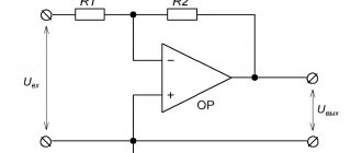
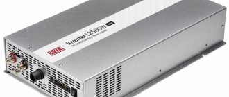
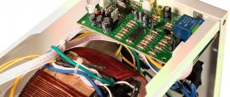
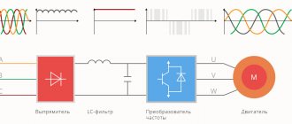
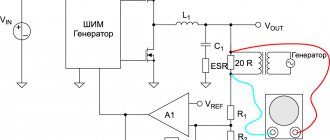
This is a circuit that steps down 24 volts to 12 volts, with a current of 20A and a power of 400 watts of a DC-DC converter. If necessary, reduce the voltage to standard 12V, some use a conventional step-down stabilizer. Perhaps this is justified if you need to connect a small car radio, but when the device operates with currents of tens of amperes, this is not an option. In the circuit of a conventional 20A linear regulator, huge losses will occur, and this is not recommended at all. The converter has much higher performance.
We get 12 Volts from 220
The most common task is to obtain 12 volts from a 220V household power supply. This can be done in several ways:
- Reduce voltage without a transformer.
- Use a 50 Hz mains transformer.
- Use a switching power supply, possibly paired with a pulse or linear converter.
Voltage reduction without transformer
You can convert the voltage from 220 Volts to 12 without a transformer in 3 ways:
- Reduce the voltage using a ballast capacitor. The universal method is used to power low-power electronics, such as LED lamps, and to charge small batteries, such as flashlights. The disadvantage is the low cosine Phi of the circuit and low reliability, but this does not prevent it from being widely used in cheap electrical appliances.
- Reduce the voltage (limit the current) using a resistor. The method is not very good, but it has a right to exist; it is suitable for powering some very weak load, such as an LED. Its main disadvantage is the release of a large amount of active power in the form of heat on the resistor.
- Use an autotransformer or inductor with similar winding logic.
Quenching capacitor
Before you begin to consider this scheme, it is first worth mentioning the conditions that you must comply with:
- The power supply is not universal, so it is designed and used only to work with one known device.
- All external elements of the power supply, such as regulators, if you use additional components for the circuit, must be insulated, and plastic caps must be placed on the metal potentiometer knobs. Do not touch the power supply board or output wires unless there is a load connected to them or unless a Zener diode or low DC voltage regulator is installed in the circuit.
However, such a scheme is unlikely to kill you, but you can get an electric shock.
The diagram is shown in the figure below:
R1 - needed to discharge the quenching capacitor, C1 - the main element, the quenching capacitor, R2 - limits the currents when the circuit is turned on, VD1 - diode bridge, VD2 - zener diode for the required voltage, for 12 volts the following are suitable: D814D, KS207V, 1N4742A. A linear converter can also be used.
Or an enhanced version of the first scheme:
The rating of the quenching capacitor is calculated using the formula:
C(uF) = 3200*I(load)/√(Uinput²-Uoutput²)
Or:
C(uF) = 3200*I(load)/√Uinput
But you can also use calculators, they are available online or in the form of a PC program, for example, as an option from Vadim Goncharuk, you can search on the Internet.
Capacitors should be like this - film:
Or these:
It makes no sense to consider the remaining listed methods, because Reducing the voltage from 220 to 12 Volts using a resistor is not effective due to the large heat generation (the dimensions and power of the resistor will be appropriate), and winding the inductor with a tap from a certain turn to get 12 volts is impractical due to labor costs and dimensions.
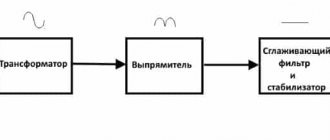
Power supply on mains transformer
A classic and reliable circuit, ideal for powering audio amplifiers, such as speakers and radios. Provided that a normal filter capacitor is installed, which will provide the required level of ripple.
In addition, you can install a 12 volt stabilizer, such as KREN or L7812 or any other for the desired voltage. Without it, the output voltage will change according to voltage surges in the network and will be equal to:
Uout=Uin*Ktr
Ktr – transformation coefficient.
It is worth noting here that the output voltage after the diode bridge should be 2-3 volts greater than the output voltage of the power supply - 12V, but not more than 30V, it is limited by the technical characteristics of the stabilizer, and the efficiency depends on the voltage difference between the input and output.
The transformer should produce 12-15V AC. It is worth noting that the rectified and smoothed voltage will be 1.41 times the input voltage. It will be close to the amplitude value of the input sinusoid.
I would also like to add an adjustable power supply circuit on LM317. With it, you can get any voltage from 1.1 V to the rectified voltage from the transformer.
Quenching capacitor instead of resistor
Sometimes the task arises of reducing the alternating voltage of a 220 volt network to a certain specified value, and the use of a step-down transformer (in this case) is not always advisable.
Let's say, a low-frequency step-down transformer, traditionally made on transformer hardware, capable of converting a power of 200 Watts, weighs more than a kilogram, not to mention the high cost.
Therefore, in some cases, it is possible to use a quenching resistor that will limit the current, but in this case, power will be released in the form of heat at the quenching resistor itself, and this is not always acceptable.
For example, if you need to power a 200 Watt lamp to only half its nominal value, you would need to dissipate 100 Watts of power into a quenching resistor, and this is an extremely dubious solution.
A very convenient alternative, for this example, can be the use of a quenching capacitor with a capacity of about 14 microfarads (this can be assembled from three metal film type K73-17, 4.7 microfarads each, designed for 250V, or better yet, 400V) this will allow you to obtain the required current without the need dissipate significant power as heat.
Let's consider the physical side of this solution. As is known, a capacitor connected to an alternating current circuit is a reactive element having capacitance associated with the frequency of the alternating current in the circuit, as well as with its own capacitance.
The greater the capacitance of the capacitor and the higher the frequency of the alternating voltage in the circuit, the greater the current passes through the capacitor, which means the capacitance of the capacitor is inversely proportional to its capacitance, as well as the frequency of the alternating current in the circuit where it is connected.
| This can also be seen from the formula for the capacitance of a capacitor: |
| If a resistor (resistive load) and a capacitor are connected in series to an alternating current circuit, then their total resistance can be found using the formula: |
And because
| So, knowing the voltage at the load, the load current and the voltage at the quenching capacitor, you can determine the capacitance of the quenching capacitor, which must be connected in series with the load to obtain the required power parameters: |
| Consider an example: you need to power a 100-watt incandescent lamp rated at 110 volts from a 220-volt outlet. First of all, let's find the value of the lamp operating current: |
We obtain a lamp current value of 0.91 A. Now we can find the required value of the quenching capacitor capacitance, it will be equal to 15.2 μF.
It should be noted that this calculation is valid for a purely resistive load when the effective value occurs. When using a rectifier, it is necessary to take into account that the effective current value will be slightly less due to the action of ripples. It should also be remembered that polar capacitors should never be used as quenching capacitors.
The best combination of vacuum and solid-state characteristics is a single-ended hybrid audio amplifier.
We do not create illusions, We make the sound alive!
How to get 12V from improvised means
The easiest way to get 12V voltage is to connect 8 1.5V AA batteries in series.
Or use a ready-made 12V battery marked 23AE or 27A, the kind used in remote controls. Inside it is a selection of small “tablets” that you see in the photo.
We looked at a set of options for getting 12V at home. Each of them has its own pros and cons, varying degrees of efficiency, reliability and efficiency. Which option is better to use, you must choose yourself based on your capabilities and needs.
It is also worth noting that we did not consider one of the options. You can also get 12 volts from an ATX computer power supply. To start it without a PC, you need to short-circuit the green wire to any of the black ones. 12 volts are on the yellow wire. Typically, the power of a 12V line is several hundred watts and the current is tens of amperes.
Now you know how to get 12 Volts from 220 or other available values. Finally, we recommend watching a useful video on the topic:
Source
Two simple ways to reduce voltage on light bulbs
If you're tired of constantly changing burnt-out lamps, use one of the tips below. But in all cases, success is achieved through a significant reduction in tension.
During the day and especially at night, the voltage in the network often reaches 230-240V, which leads to accelerated burnout of the filaments of electric lamps.
It is estimated that an increase in voltage by only 4% compared to the nominal (that is, from 220 to 228V) reduces the service life of electric lamps by 40%, and with an increased “power” of 6%, this life is reduced by more than half.
At the same time, reducing the voltage on the lamps by only 8% (to 200-202V) increases the “experience” of their operation by 3.5 times; at 195V it increases almost 5 times
Of course, with a decrease in voltage, the brightness of the glow also decreases, but in many cases, in particular in office premises and in public areas, this circumstance is not so important
How to reduce the voltage on electric lamps? There are two simple ways.
First
- turn on two lamps in series (Figure 1). What kind of lamp should I take as an additional one? It can be the same as the main one. But then both lamps will shine weakly.
It is best to select a lamp so that the power of the lamps differs by 1.5-2 times, for example, 40 and 75 W, 60 and 100 W, etc.
Then the lamp of lower power will glow quite brightly, and the more powerful one will glow weaker, acting as a kind of ballast that dampens excess voltage (Fig. 2.).
At first glance, there is no gain - after all, you have to use two lamps at once instead of one. But this is what the simplest calculation shows; The voltage drop across lamps when connected in series is distributed inversely proportional to their power.
Therefore, with a network voltage of 220V (let’s take a pair of lamps of 40 and 75 W), the voltage on a 40-watt lamp will be about 145V, and on its 75-watt “partner” it will be slightly more than 75V.
Since longevity depends on the voltage, it is clear that you will mainly have to change the lamp of lower power. And even that, as practice shows, in the worst case, lasts at least a year.
Under normal conditions, during the same time it is necessary to change from 5 to 8 lamps (this means daily operation for 12 hours). As you can see, the savings are quite significant.
Another
method - sequential connection of a lamp and a semiconductor diode. Due to its small size, it can be installed in the switch cone between the terminal and one of the supply wires. With this option, a barely noticeable flickering of the lamps occurs (due to half-wave rectification of the alternating current), and the average voltage across them is about 155V. Now about choosing the type of diode. It must have a certain allowable current reserve and be designed for a voltage of at least 400V. Of the miniature diodes, the KD150 and KD209 series meet this requirement. However, diodes of the KD105 brand should be used with lamps whose power does not exceed 40 W, and KD209 diodes (with any letter index) should be used in conjunction with 75-watt lighting devices. Of course, you can use more powerful diodes of other types, but then they will have to be installed outside the switch. A properly selected diode lasts almost unlimited time. Now let's look at one more question. What should you do if the house has a common switch for the entire entrance? In this case, install one high-power diode. It is mounted on a metal corner, screwed with screws to the wall next to the switch, and covered with a casing with ventilation holes. Recommended types of diodes: KD202M, N, R or S, KD203, D232-D234, D246-248 with any letter index. When choosing the type of diode, remember that its maximum permissible operating current (indicated in the passport of the semiconductor device) should be 20-25% higher than the total current consumed simultaneously by all lamps related to this switch. If the diode allows the current of all lamps (it is easy to calculate by dividing the total power of all lamps by the network voltage of 220V) it should not exceed 4A.
Voltage reduction using transformers
The easiest way is to use a reduced voltage transformer that does the conversion. The primary winding contains more turns than the secondary winding. If there is a need to reduce the voltage by half or three times, the secondary winding may not be used. The primary winding of the transformer is used as an inductive divider (if there are taps from it). In household appliances, transformers are used, from the secondary windings of which voltage of 5, 12 or 24 Volts is removed.
These are the most commonly used values in modern home appliances. 20-30 years ago, most equipment was powered by a voltage of 9 Volts. And tube TVs and amplifiers required a constant voltage of 150-250 V and an alternating voltage of 6.3 for filaments (some lamps were powered by 12.6 V). Therefore, the secondary winding of the transformers contained the same number of turns as the primary. In modern technology, inverter power supplies are increasingly used (as on computer power supplies), their design includes a step-up transformer, it has very small dimensions.
