Device
There is a wide variety of pulse relays on the market; due to technical and design differences, you can find different devices. But as an example, we will consider the simplest and most practical principle of operation for understanding (see Figure 1).
Rice. 1. Example of a pulse relay device
The simplest example of a pulse relay consists of the following elements:
- Coil - made of a copper conductor wound on a non-magnetic base, for example, a frame made of textolite, electrical cardboard, etc. Designed to create an electromagnetic field that affects magnetic elements.
- The core is made of ferromagnetic materials that interact with the magnetic field of the coil. Designed to move and perform magnetic influence.
- Relay contact system - consists of movable and fixed contacts designed to transmit a signal.
- Resistive, capacitive and signal elements are used to set the operating logic of the device and indicate the state.
- Timer – sets the time interval for the relay, but is not present in all models; it helps to significantly expand the functionality of the equipment.
Designation and marking
You might be interested in: The design and operating principle of an incandescent lamp
What kind of lighting do you prefer?
Built-in Chandelier
In normally closed notation, terminals in a circle are drawn intersecting. The designation of the three-contact device looks different. A circle is still drawn in the same way, but in it, on the one hand, two parallel segments are depicted, and on the other, a segment located in the center of the distance between them. The switching contact is also drawn on it.
According to Soviet standards, on diagrams and in literature, the reed switch is signed with the letter “K”, after which the serial number of the product on the diagram is placed. The foreign designation uses two Latin letters SF.
There is no standard for product labeling. Each manufacturer usually puts its own factory designation on the reed switch body: for example, KEM, TRA, ASMK, KA, KSK. Therefore, to find out what type a particular device is, you will need to look at the manufacturer’s datasheet.
Select error category
Basket
By clicking on the “Yes” button, you consent to the processing of personal data and receiving our advertising newsletter. You can unsubscribe from receiving emails in your personal account.
Warning
Agreement
Rules for publishing user content:
- Publication of content (reviews, comments, questions or answers) occurs only after their preliminary moderation;
- Review verification may take from 1 to 7 days. A letter about publishing a review will be sent to the Email you specified in your personal account;
- The moderator may make changes to the review related to punctuation and spelling, but tries to preserve the author's style;
- The maximum length of a review is no more than 1500 characters (including spaces).
How to write a good review:
The review will not be published if:
- Contains obscene language or any insults;
- Contains a large number of lexical, spelling and other errors;
- Typed in Latin letters;
- Typed exclusively in uppercase letters;
- Feedback of an advertising nature (telephone numbers, addresses, links to other sites);
- Any other extraneous text.
Please understand that the site editors reserve the right not to publish reviews that do not meet the requirements listed above, and also reserve the right to delete any review at any time without giving reasons and without prior approval from the author of the review.
Contactor (switch).
There are impulse switches (bistable remote switches) with multiple changeover contacts, which are sometimes called "bistable contactors".
Expert opinion
It-Technology, Electrical power and electronics specialist
Ask questions to the “Specialist for modernization of energy generation systems”
223156 Contactor NC1-9511 95A 230V/AC3 1NO 1NC 50Hz complies with the ROHS (CHINT) standard - buy in the electrical goods catalog Switching DC voltage, which is problematic because the switching arc with mechanical contacts does not go out when crossing zero. Ask, I'm in touch!
Principle of operation
The principle of operation of a pulse relay is to move the contact group under the influence of the electromagnetic field of the coil that retracts the core. In this case, the device is controlled through push-button channels. One press of the button sends a short-term pulse to the control output, and the contacts go into a stable state - supplying or turning off voltage, which is why it is also called bistable (two stable states). Unlike the same contactor, such a relay is controlled by a single pulse supplied by a button or switch with self-return to its original state, hence the name pulse relay.
For example, consider the operation of a specific device model - RIO-1 (see Figure 2):
Rice. 2. Operating principle of the RIO-1 relay
This device contains two groups of contacts - power and control. Power contacts are represented by terminals 11, 14 and N, control terminals Y, Y1, Y2; it should be noted that in other modifications of pulse relays the markings and number of contacts will be different. Let's consider the purpose of each of the inputs in order:
- 11 – designed to supply power to it from the electrical network;
- 14 – used to supply phase from a pulse relay to the connected load;
- N – terminal for connecting the neutral wire from the common bus;
- Y – universal input, when a control pulse is applied to which, the relay switches to the opposite state - from on to off and back;
- Y1 – is intended exclusively for switching the pulse device to the on state, that is, if the contacts are already closed, the relay will remain in the same position and has priority over the Y input;
- Y2 – switches the pulse device to the off state, has priority over the other two outputs.
A distinctive feature of RIO-1 is that the power circuit breaks only when the alternating voltage sinusoid passes through zero, which significantly increases the service life of the contact group. But at the same time, the response time differs by 0.3 s, which must be taken into account for the design of precise electronic circuits. The operation of a pulse relay through the supply of signals to each input is clearly displayed on the device’s timing diagram (see Figure 3):
Rice. 3. Timing diagram of RIO-1
As you can see in the figure above, the methods for turning on and off a pulse device are represented by four periods of interaction:
- When you press the button and apply a pulse signal to input Y, the operating voltage will be removed from the power output until the second signal is applied to input Y. This is the simplest option for controlling, for example, a lighting system.
- In the off state, pulse control is applied to input Y1, resulting in an operating rating of 220V at output 14. If you need to turn off the same lighting on site, just send a signal to Y and the power will stop.
- By applying a pulse signal to input Y1, the power circuit is closed - the potential is removed from output 14. When potential Y2 is applied, the bistable relay will turn off and the power circuit will open.
- During this period, switching is performed by applying a signal to input Y. And by applying a pulse signal to Y2, the switch contacts open.
This operating logic allows for the implementation of a number of interesting solutions, both in domestic and industrial processes. This will ensure priority switching of certain objects and electrical equipment located in them.
Modular contactor Legrand and Schneider Electric.
Legrand CX and Schneider Electric iCT contactors in purpose, noiselessness and technical characteristics to ABB , but they also have several advantages:
- The modular contactor ABB 40 and 63A has strictly 4 contacts, there is no less, and occupies three modules. Legrand and Schneider Electric have 40 and 63A contactors with only two contacts, which is sufficient for a single-phase electrical network, because They take up less space in the electrical panel (two modules), which is a whole module less than ABB.
- Such a modular contactor from Legrand or Schneider Electric, which takes up less space, and costs lessthan an ABB starter.
Thank you for your attention!
Varieties
A wide selection of pulse relays provides a fairly large assortment, differing in both pricing policy and functionality provided. According to the principle of operation, all models can be divided into electromechanical and electronic (Figure 4).
Figure 4. Electronic and electromechanical relay
The first option involves mechanical movement of the elements of the pulse device due to electromagnetic interaction between the coil and the core. The second type is controlled by semiconductor elements and switches without mechanically opening contacts and moving parts.
In addition, pulse relays may differ in:
- Rated load - indicates the permissible amperage that can be connected to the power contacts;
- Number of poles - can have a different number of inputs and outputs to implement certain tasks;
- Installation method - can be mounted on a DIN rail in accordance with section 1 of GOST R IEC 60715-2003, a bracket or other placement option;
- Purpose – the most popular are pulse relays for controlling lighting, protection and alarm circuits.
Also, bistable devices differ in overall dimensions, case materials, and the presence or absence of signal lamps.
In technology
Normally closed contacts are a device design that has closed contacts when not in use.
An electromagnetic relay is actively used to control various actuators, switch circuits, and control devices in electronics.
The relay design is quite simple. Its basis is a coil consisting of a large number of turns of insulated wire.
soft iron rod is installed inside the coil The result is an electromagnet. There is also an anchor . It is attached to a spring contact . The spring contact itself is fixed to the yoke . Together with the rod and the armature, the yoke forms a magnetic circuit.
If the coil is connected to a current source, the resulting magnetic field magnetizes the core. He, in turn, attracts the anchor. The anchor is mounted on a spring contact. Next, the spring contact closes with another fixed contact. Depending on the relay design, the armature may mechanically control the contacts differently.
Relay device.
In most cases, the relay is mounted in a protective housing. It can be either metal or plastic. Let's look at the relay device more clearly, using the example of an imported electromagnetic relay Bestar . Let's take a look at what's inside this relay.
Here is the relay without the protective housing. As you can see, the relay has a coil, a rod, a spring contact on which the armature is attached, as well as actuating contacts.
Expert opinion
It-Technology, Electrical power and electronics specialist
Ask questions to the “Specialist for modernization of energy generation systems”
Buy Prefix kont. 1NO 1NC for contactors TeSys E SchE LAEN11 wholesale, price Electrical installations and electric motors are controlled by starters, but do not protect them when the voltage drops, since the power contact opens, and the operation of the device to which the electromagnet is distributed is suspended and independent switching is excluded. Ask, I'm in touch!
Connection diagrams
In practice, pulse relays have found a fairly wide range of applications, but in everyday life they are most often used to turn on lamps from different points in the room. Therefore, as examples, we will consider the possibility of connecting pulsed devices to transmit power to light bulbs through a switch.
The simplest option is when you power only one chandelier or group of spotlights in a room, which must be turned on and off from several points in the room.
Rice. 5. The simplest IR connection diagram
As you can see in Figure 5, power directly from the machine or distribution box is supplied to input 11 RIO-1, the second line is connected to the switches with a loop, and the common point is output to input Y. From output 14, the phase is supplied to the lighting lamps, and the neutral conductor to the common The blocks are routed in a separate line to the lamps and the corresponding output of the pulse relay. With this scheme, each of the switches equally sends a signal to both turn on and turn off the lighting equipment. In addition, you can implement more complex connection schemes with priority setting.
Rice. 6. Connection diagram for two groups of consumers
As shown in Diagram 6, there are two groups of lighting fixtures here; we can take an analogy with two rooms, each of which has its own RIO-1 installed. Connecting the three switches for each lighting group is done in the same way, but global on/off functionality is added to both groups.
Here, a push-button switch, designed to supply power to all lighting devices, is connected to the Y1 terminal of both the first and second pulse relays. Therefore, when switching “On”, despite the state of the switches and the signal being sent to Y, the light will turn on in both rooms. The de-energizing switch is connected to the Y2 terminals of both impulse relays, which takes precedence over Y1. Therefore, when you press the “Off” key, all lighting equipment will turn off.
What additional accessories do you need to purchase to connect a pulse relay?
To install the circuit you will need:
- push-button switches in a quantity corresponding to the number of control places;
- power wire or cable that can withstand the main load from the lamps;
- low-current wiring that provides parallel connection of all buttons with impulse relays
- a common electrician's tool.
Pushbutton switches
Any models that operate without fixing the pressed position with self-return due to the force of the built-in spring are suitable. It can be:
- custom-made unique products with an original design and one, two, three keys in a common body;
- redesigned light switches;
- door lock buttons, even equipped with a backlight indicator;
- other similar devices.
Such push-button products can be successfully integrated into the beautiful interior of an apartment.
The function of self-return of the button to the off position by the built-in spring is important: some manufacturers indicate in the descriptions that the time of applying voltage to the coil should not exceed one minute - otherwise its insulation may burn out.
Do not place these buttons where they could be accidentally pressed by a random foreign object (the back of a chair, a vase or a book on the table). Yes, and children need to be explained that they shouldn’t play with the light for a long time.
From the point of view of an electrician, for the reliability of the circuit, we are interested in the fact that when the button is pressed, its contact should close, and after releasing it, reliably return to the open position.
Power wire for lighting
Among the large assortment of modern wires and cables, in principle, you can choose any one that suits the price and operating conditions in household wiring.
To ensure safety and reliability of long-term operation, it is important to correctly calculate its load power characteristics. Our online calculator is designed to make this process easier.
Low current wiring
In principle, any wire or cable will do, but due to the short-term effect of a very small load, it makes sense to save on its cost and dimensions and use a regular copper telephone “noodle” or twisted pair with a certain number of cores.
You can also use any thin copper conductor. When choosing it, the main attention should be paid to only two questions:
- state of electrical insulation;
- mechanical strength of cores capable of withstanding loads during installation and operation.
Specifications
In accordance with clause 2.1. GOST 16121-86 parameters of pulse relays must comply with the technical specifications and standards on the basis of which they are manufactured. The most relevant for the operation of bistable switches are:
- the number of push-button switches that can be connected together with a certain type of lamp;
- limits of permissible voltage for switching;
- maximum current load permissible for switching;
- permissible number or power of light bulbs of a certain type;
- overall dimensions must correspond to passport data in accordance with clause 2.2.1 of GOST 16121-86
Fig.7. Example of overall dimensions of a pulse relay
- signal time and response delay;
- mechanical and electrical strength of structural elements;
- wear resistance by number of cycles;
- Climatic performance.
Some of this data can be found on the body of the pulse relay (see example in Figure 8), others only in the device passport.
Rice. 8. Relay characteristics
What must be done before installation work begins?
Laying wires is one of the dirty jobs associated with the processing of walls and building structures. They must be completed quickly and not drawn out over time. This will require quality preparation.
It includes:
- drawing up a plan of rooms on paper depicting on it the end points and routes for laying all electrical lines;
- transfer of technical solutions directly to building structures;
- final clarification of the consumption of required materials;
- preparation of the necessary tools.
The room plan is drawn to scale. It is convenient to use graph paper or a regular notebook sheet in a box.
It is worth considering that modern computer programs greatly facilitate this process, allowing you to create accurate electronic documents. They are convenient to store on different media and print on a printer.
One of the available programs for home use is Visio from Microsoft. As an example, I made a room plan in it and described the process in a separate article. You can use it.
Marking the walls for wiring is done with a regular pencil and a long ruler. Auxiliary tools include a plumb line or spirit level, and a laser level.
The remaining preparation issues should not cause difficulties for the average home master.
Application
The scope of application covers all areas where automation requires remote control of one object from several points. In everyday life and some industries, this is room lighting that can be controlled from several points. This issue is especially relevant for organizing the power supply of a “smart home”.
In automation and centralization systems on the railway network, it provides telecontrol and dispatch signaling processes. Used for signaling and transmitting operating signals.
Design and principle of operation of a magnetic starter
The contactor device is somewhat similar to an electromagnetic relay - it also has a coil and a group of contacts. However, the contacts of the magnetic starter are different. Power contacts are designed to switch the load controlled by this contactor; they are always normally open. There are also additional contacts designed to implement starter control (this will be discussed below). Auxiliary contacts can be normally open (NO) or normally closed (NC).
In general, the magnetic starter device looks like this:
When control voltage is applied to the starter coil (usually the coil contacts are designated A1 and A2), the moving part of the armature is attracted to the stationary part and this leads to the closure of the power contacts. Additional contacts (if any) are mechanically connected to the power contacts, therefore, at the moment the contactor is triggered, they also change their state: normally open ones close, and normally closed ones, on the contrary, open.
References
To prepare the article, the following technical literature was used:
- Iglovsky I. G., Vladimirov G. V. “Handbook on low-current electrical relays” 1984
- Filipcheiko I, P., Rybin G. Ya. “Electromagnetic relays” 1968
- Gurevich V.I. "Electrical relays. Device, principle of operation and application. Engineer's Handbook" 2011
- Sivukhin D.V. “General course in physics” 1975
- Obolentsev Yu.B., Gindin E.L. “Electrical lighting of general industrial premises” 1990
Connecting the motor via a starter with a thermal relay
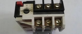
The figure shows a magnetic starter with a thermal relay installed on it. When heated, the electric motor begins to consume more current - this is detected by a thermal relay. On the body of the thermal relay, you can set the current value, the excess of which will cause the relay to operate and close its contacts.
The normally closed contact of the thermal relay uses the starter coil in the power circuit and breaks it when the thermal relay is activated, providing an emergency shutdown of the engine. The normally open contact of a thermal relay can be used in a signal circuit, for example, to light an “emergency” lamp when the electric motor is turned off due to overheating.
