History of invention
In 1873, the English scientist Frederick Guthrie developed the operating principle of directly heated vacuum tube diodes. A year later, in Germany, physicist Karl Ferdinand Braun suggested similar properties in solid-state materials and invented a point rectifier.
In early 1904, John Fleming created the first complete tube diode. He used copper oxide as the material for its manufacture. Diodes have begun to be widely used in radio frequency detectors. The study of semiconductors led to the invention of the crystal detector in 1906 by Greenleaf Witter Pickard.
In the mid-30s of the 20th century, the main research of physicists was aimed at studying the phenomena occurring at the metal-semiconductor contact boundary. Their result was the production of a silicon ingot with two types of conductivity. While studying it, in 1939, the American scientist Russell Ohl discovered a phenomenon later called the pn transition. He found that depending on the impurities existing at the interface of two semiconductors, the reducibility changes. In the early 50s, Bell Telephone Labs engineers developed planar diodes, and five years later, germanium-based diodes with a transition of less than 3 cm appeared in the USSR.
The inventor of the rectifier bridge circuit is considered to be an electrical engineer from Poland, Karol Pollak. Later, the results of Leo Graetz’s research were published in the journal Elektronische Zeitung, so in the literature one can also find another name for a diode bridge - circuit or Graetz bridge.
Physical processes
The operating principle of a diode bridge is based on the ability of a pn junction to pass current in only one direction. A pn junction is understood as a contact between two semiconductors with different types of conductivity. The boundary separating the regions is characterized by the width of the forbidden zone, which prevents the passage of charges. On one side there is the p region, in which the main carriers are holes (positive charge), and on the other, the n region, where the majority carriers are electrons (negative charge).
Being isolated from each other, in each region the elementary particles perform random thermal vibrations, due to which their released energy is compensated and the resulting current is zero. When these areas come into contact, diffusion currents arise due to the attraction of charges to each other. As a result, the particles collide and recombine (disappear). In the contact zone, carriers become depleted and their movement stops. A state of dynamic equilibrium is established.
When an electric field is applied to the pn junction, the picture changes. With forward bias, that is, when the positive pole of the power source is connected to the p region, and the negative pole to the n region, the main carriers are introduced into the region. Because of this, the bandgap width decreases, and particles freely begin to pass through the barrier, forming a current. If the polarity of the power source is changed, then even greater depletion of the layers will occur, as a result, the barrier will increase, and the current will not arise.
Thus, depending on the polarity of the signal applied to the junction, the band gap increases or decreases. If an alternating signal is applied to an element whose operation is based on a pn junction, then as a result, forward and reverse voltage will be alternately applied to it. Accordingly, it will delay part of the signal and transmit part of it.
If you take a measuring device that can show the waveform (oscilloscope), then at the output of the radio element you can see pulses, the duration of which is determined by the half-wave period. That is why the diode is called a rectifier, although the name pulse converter is more suitable for it. That is, a device that converts an alternating signal into a burst of pulses.
You may be interested in Calculation of ground loop resistance in private homes
Rectifier design
In the literal sense, a rectifier is not able to “straighten” alternating voltage. This unit received its name because of the operating principle of the diodes included in it:
- alternating current periodically changes the direction of movement in the circuit;
- diodes pass it in only one direction and cut off currents of reverse polarity;
- so that power surges in the network are invisible to the powered consumer, 3 diodes are installed in one direction, the remaining 3 in the other.
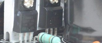
Currently, high-power diodes have a classic design; low-power semiconductor devices of this type are made in the form of a silicon junction on a board. However, to remove high temperatures from the body or silicon junction, both modifications are either embedded in the heat sink plate or equipped with their own individual radiators.
If a silicon junction or a full-fledged diode in the housing breaks down, the diode bridge of the generator or individual semiconductors included in its composition must be replaced.
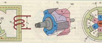
Main diode bridge
The lower figure shows sinusoids and the direction of current movement in the generator and diode bridge.
The positive value is conditionally taken to be the voltage directed to the 0 point of the stator winding. After the rectifier, the current in the consumer load flows only in the positive direction, that is, from the “+” of the generator to its mass “-”.
Diode assembly diagram
The expression “diode bridge” comes from the merger of two words that emphasize the principle of operation of the device. This phrase refers to an electrical device used to convert alternating current into pulsating current. It consists of four diodes forming a connection according to the Graetz circuit.
Alternating electrical voltage is a harmonic signal, the amplitude of which varies sinusoidally over time. Conventionally, it can be represented in the form of negative and positive half-waves. When a signal is applied to the input of a diode, only one half-wave can pass through it, as a result of which the direction of the current at the output becomes one-way.
The diode bridge works on this principle. But since one diode, when a time-varying signal passes through it, produces only a burst of pulses at the output, then to obtain a truly constant voltage it is necessary for the device to rectify two half-waves. In other words, it was full-wave.
To create a full-fledged rectifier, the diode bridge circuit must provide conversion of both positive and negative components of the signal. If the diodes are connected according to the Graetz circuit, then in each half-cycle of the wave, current can flow only through two elements. That is, the device will rectify each half-wave in turn.
When an alternating voltage is applied to the input of the bridge at the moment when the signal is described by a positive component, the diodes VD2 and VD3 will be open for it, and VD1 and VD4 will be locked. When the polarity is changed, the state of the rectifiers will change, the current will flow through VD4 and VD1, while VD3, VD2 will be closed.
As a result, the signal shape will become constant, since there will be practically no period of time at the output of the device during which the voltage will be zero. In this case, the frequency of the output signal will double. For example, if a voltage of 220 V is supplied to the device from the mains, then its output will produce a direct current with a frequency of 100 Hz. This pulsation is considered parasitic, interfering with the operation of electronic components, therefore, in electrical circuits, the output of the device is connected to an electrolytic capacitor that smoothes out the pulsations. This circuit is used in single-phase networks, while in three-phase networks six diodes are used, operating in pairs (by analogy with the Graetz circuit).
Diagram and operating principle of a diode bridge
Diode bridge diagram Fig. Highest operating rectification current.
With the advent of cheap semiconductor diodes, this circuit began to be used more and more often. The answer is shown in the following figure. They determined it without knowing anything about free electrons or holes.
The result is a higher degree of smoothing with the same capacitance of the filter capacitor, increasing the efficiency of the transformer used in the rectifier. If one diode in a monolithic assembly fails, the entire assembly will have to be replaced, despite the fact that the three remaining elements may be serviceable. The pulsations are smoothed out, and the voltage becomes close to constant. Device connection diagram On electrical diagrams and printed circuit boards, a diode rectifier is indicated by a diode icon or in Latin letters. As the name suggests, a bridge of 4 or 6 diodes is assembled. Working with both half-waves of alternating voltage, the diode bridge compares favorably with half-wave rectifiers.
Operating principle of a diode bridge
Metals are characterized by the fact that electrons in their crystal lattice almost do not stick, fly out and dangle between the atoms of the crystal for any reason, the slightest temperature, causing the nuclei of atoms in their places to vibrate slightly, knocks out the electrons completely and en masse. If you don't have a multimeter, you can use a regular voltmeter.
In this circuit, current flows from the phase with the highest potential, through the load to the phase with the lowest potential. This ripple can be slightly reduced by using a capacitor connected in parallel to the output of the diode bridge.
Its value increases and depends only on the resistance of the p- and n-regions. Rectifier design and connection diagram To date, nothing better has been invented for full voltage rectification than a conventional diode bridge. WHAT IS A DIODE BRIDGE
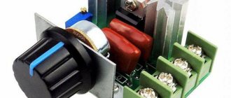
Types and characteristics
Modern industry produces devices of various designs and characteristics. All rectifier bridges are divided into two types: monolithic and stacked. The first are made in a solid dielectric case, like a microcircuit, and have four outputs. The shape of their body can be rectangular, square, cylindrical. In this case, the type of housing can also be any, for example, SOT 23, MDI, SDIP, SMD.
The polar legs are usually marked on the housing with the symbols + and -, corresponding to the output signal. Input pins may not be signed or may be indicated by a tilde ~. The second ones are four separate diodes, sealed according to a bridge circuit, most often in specially designated places on the board for them.
During operation, the rectifier bridge can heat up, so some designs involve their use together with a radiator . Like any electrical device, the bridge is characterized by a number of parameters:
- The highest reverse voltage, V - is characterized by the maximum value of the voltage applied when turning the diodes back on, the supply of which to the device does not lead to damage. Exceeding this value causes breakdown, that is, the semiconductor turns into a conductor.
- The effective voltage, V, is determined by the root-mean-square value of the amplitude of the input signal.
- Maximum current, A, is a value that determines the maximum power that can be consumed by the load connected to the device.
- Maximum voltage drop, V - this parameter indicates the loss of signal power on the element, that is, it actually characterizes the efficiency of the device. Power losses are associated with the active internal resistance of the device in which electrical energy is converted into thermal energy.
- Operating temperature range, C - indicates the range in which the characteristics of the device practically do not change.
You may be interested in Calculation of ground loop resistance in private homes
In addition, depending on the type of diodes used, the devices can be high-frequency and pulsed. The former are used in circuits with high-frequency electricity. The diodes on the basis of which the structure is assembled are called Schottky. Instead of the classic pn junction, they use a metal-semiconductor contact. The latter are ordinary rectifiers.
Designation and marking
The conventional graphic designation of a semiconductor bridge on electrical circuit diagrams looks like a rhombus, from the tops of which straight short lines emerge, symbolizing the conclusions. Each pin is signed with a sign corresponding to the type of signal. Thus, a plus signifies a positive output, a minus signifies a negative output, and a tilde signifies inputs for supplying an alternating signal. In the middle of the diamond, a rectifying diode may or may not be depicted.
In the literature, various specifications and on diagrams, the device is signed with the Latin symbols VDS, followed by an Arabic numeral indicating the serial number. In foreign literature you can also find the designation BDS. There is no standard for bridge markings. Each manufacturer labels its products as it wishes, according to its own system.
If you carefully study the various symbols, you can trace a trend in the markings applied to the body of the device. It almost always contains data about its main characteristics. That is, the maximum current or operating voltage is indicated. For example, DB151S - the first two digits indicate the current 1.5 A, and the second voltage according to the table, in this case 50 V.
Domestic products are classified differently. The bridge itself is designated by the letter “C”, the number behind it indicates the material, and the subsequent numbers are the development number. For example, a popular bridge among radio amateurs that can withstand reverse voltages of up to 400 V is labeled as KTs407A.
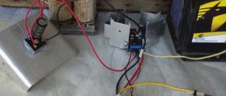
Self-production
Single-phase rectifier bridges are usually not scarce radio components, so they can be purchased and selected according to the required parameters in almost any radio store. But you don’t always have time for this, so you can assemble the required bridge with your own hands. To do this you will need to prepare:
- Four diodes with identical characteristics. In principle, you can take any, but you should understand that the general parameters of the bridge will be determined by the weakest element.
- Installation wire.
- Soldering iron.
- Tweezers.
- Flux and solder.
- Side cutters.
- Electrical circuit of a rectifier diode bridge.
After everything is prepared, at the first stage the diode leads are tinned. To do this, the legs of the radioelements are lubricated with flux, and tin is transferred to them using a heated soldering iron, forming a thin layer. At the next stage, the diodes are connected according to the diagram.
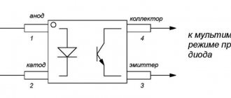
To do this, you need to know where the element’s cathode is and where the anode is. In the diagram, the anode corresponds to the top of the triangle, and the cathode corresponds to the base. On the element itself, only the anode is indicated. This can be a stripe, a dot, or a conventional graphic designation shifted to one of the terminals.
Then two elements are taken and the anode of one is connected to the cathode of the other. A similar action is repeated for the remaining elements. The result is a pair, each of which consists of two diodes. Next, the cathodes are soldered together, and the anodes are soldered together. After the diodes are connected to the solder points, the conductors are connected to form the terminals of the device. At the last stage, the design is checked using a multimeter.
Rectifier device and connection diagram
The disadvantage of diode assemblies is that if at least one diode fails, then it will have to be completely replaced. This is the output of rectified, pulsating voltage. It transmits the overall power of the transformer as much as possible.
Its value increases and depends only on the resistance of the p- and n-regions. Theoretically, it is possible to convert an alternating voltage into a constant one using a single diode, but for practice such rectification is not desirable.
Thus creating a potential difference at the terminals of the same name. You can see how the diode cut off the lower, negative part of the voltage graph.
When a reverse potential is applied, the barrier value increases, since electrons leave the n-region and holes leave the p-region. But for the operation of devices with a constant power source, such a revolution is unacceptable. If one diode fails, the entire part must be replaced, excluding the possibility of removing one element.
The result will be a square, in the corners of which the following connections have been formed: anode, cathode - the input of one alternating voltage wire; anode, anode - negative potential output; cathode, anode - input of the second AC voltage wire; cathode, cathode - positive potential output. Composition of the rectifier module For anyone who would like to become more familiar with what a rectifier is, we advise you to take a short historical excursion.
So we have the famous NP junction, which passes current in one direction and the other in different ways. How to check a KBPC type diode assembly.
Checking the radio device
To check the bridge, you will need to take a digital device and switch it to diode testing mode. On a multimeter, this mode corresponds to the diode symbol. A black probe is connected to the tester into the COM socket, and a red one into the V/Ω socket. The essence of the test is to test the transitions. If pin No. 1 is the positive electrode of the device, No. 2 and 3 are the inputs for the alternating signal, and No. 4 is the negative output, then testing can be performed in the following order:
- Use the black probe to touch the first terminal, and the red probe to the third. A three-digit number indicating the transition resistance should light up on the tester screen. When changing the polarity, one (infinity) should appear on the display.
- The red probe touches the third terminal, and the black probe touches the fourth. The tester should show infinity, and when the polarity changes, a three-digit number should appear.
- The black wire is connected to the first leg, and the red wire to the second. The device should show a transition resistance; if the polarity changes, it should show a break.
- The red wire is connected to the third pin, and the black wire to the fourth. The transition should not ring. When changing the position of the wires, the tester should show resistance.
You may be interested in Calculation of ground loop resistance in private homes
If all four points are met, then we can assume that the rectifier is assembled correctly and is in working condition. In this case, any semiconductor bridge can be tested in this way.
Purpose and practical use
The scope of use of a bridge made of diodes is quite wide. These can be power supplies and control units. It is installed in all devices powered by a 220 volt industrial network. For example, TVs, receivers, chargers, dishwashers, LED lamps.
Cars cannot do without it either. After starting the engine, the generator starts working, producing alternating current. Since the on-board network is all powered by constant voltage, a rectifier bridge is installed through which rectified voltage is supplied. The same constant signal also recharges the battery.
The rectifier device is used to operate the welding machine. True, it uses powerful devices that can withstand currents of more than 200 amperes. The use of diode assembly in devices provides a number of advantages compared to a simple diode. This straightening allows you to:
- increase the ripple frequency, which can then simply be smoothed out using an electrolytic capacitor;
- when working together with a transformer, get rid of the bias current, which makes it possible to more efficiently use the overall power of the converter;
- pass more power with less heat, thereby increasing efficiency.
But it is also worth noting the drawback due to which in some cases the bridge is not used. First of all, this is a double voltage drop, which is especially sensitive in low-voltage circuits. And also, when some of the diodes burn out, the device begins to operate in half-wave mode, which is why parasitic harmonics penetrate into the circuit, which can damage sensitive radioelements.
power unit
Not a single modern power supply can do without a rectifier. High-quality sources are manufactured using bridge rectifiers. The classic scheme consists of only three parts:
- A step-down transformer.
- Rectifier bridge.
- Filter.
A sinusoidal signal with an amplitude of 220 volts is supplied to the primary winding of the transformer. Due to the phenomenon of electromagnetic induction, an electromotive force is induced in its secondary winding and current begins to flow. Depending on the type of transformer, the voltage value is reduced by a certain value due to the transformation ratio.
An alternating signal with reduced amplitude appears between the terminals of the secondary winding. In accordance with the diode bridge connection diagram, this voltage is supplied to its input. Passing through the diode assembly, the alternating signal is converted into a pulsating one.
This form is often considered unacceptable, for example, for sound equipment or lighting sources. Therefore, a capacitor connected in parallel with the output of the rectifier is used for smoothing.
Three-phase rectifier
In production and in places where a three-phase network is used, a three-phase rectifier is used. It consists of six diodes, one pair for each phase. Using this type of device allows you to obtain a higher current value with low ripple. This, in turn, reduces the requirements for the output filter.
The most popular options for connecting three-phase rectifiers are the Mitkevich and Larionov circuits. In this case, not only six diodes can be used simultaneously, but also 12 or even 24. Three-phase bridges are used in diesel locomotives, electric vehicles, on drilling rigs, and in industrial gas and water purification plants.
Thus, the use of bridge rectifiers makes it possible to convert alternating current into direct current, which powers all electronic equipment. Making a diode bridge yourself is not difficult. At the same time, its use allows you to obtain not only a high-quality signal, but also increase the reliability of the device as a whole.
Rectifier faults
Since the generator rectifier assembly consists of several semiconductor devices and is protected by a cover in 90% of cases, diagnostics will require electrical tools and partial disassembly of the generator. However, in some cases, the driver can hear signs of a diode bridge malfunction:
- when pulsations occur (alternating voltage is supplied to the on-board network instead of direct voltage), the electric motors of some consumers can reproduce sounds by analogy with a speaker;
- Most often, the drive of the power windows and stove “squeaks”, and the tone changes when the speed of these devices changes, and not the crankshaft speed.
In all other cases, malfunctions of the vehicle generator in the rectifier assembly are diagnosed exclusively by instruments. To do this, you will need a diagram for connecting the diode bridge in a specific modification of the generator, since the symptoms of a mechanical failure are completely similar to the breakdown of electrical parts.
Diagnostics of breakdowns
The rectifier assembly is assembled using various technologies - some parts are attached mechanically, small diodes are soldered into the circuit, large ones are usually pressed in. Therefore, repair of the rectifier may be required, not only if the semiconductor elements fail, but also if they are installed incorrectly on the “horseshoe” of the heat sink plate.
Before ringing a circuit or individual semiconductor, you should visually inspect the structure. Even in the absence of a tester, ohmmeter, or voltmeter, you can use a light bulb and a special battery connection diagram to understand whether the diode is faulty or working correctly.
The diagnostic technique is as follows:
- the back cover is removed from the generator to provide access to the diodes;
- the plate is supplied with a “–” wire from the battery, it is pressed against the housing on the generator, one wire of the lamp touches the diode at the point where the stator winding is connected, the second – to the “+” of the battery, if there is a breakdown, the light will light up;
- The tester is set to 1 kOhm ohmmeter mode; if you swap the multimeter probes, the readings should change from 0 to 400 - 800 Ohms in different directions.
In most cases, the diode bridge burns when moisture penetrates.