There are many different devices, which during their operation often have to be moved from one place to another, each time connecting them to a three-phase network. There are often cases when an inexperienced worker, when connecting equipment, violates the phase sequence, which can lead to equipment failure. To prevent this, it is necessary to ensure phase control by installing a special protection device. In this material we will talk about what a phase control relay is, what is its connection diagram and consider the operating principle of this device.
Relay functionality
The phase control relay (PKF) is designed to protect industrial and household electrical equipment from abnormal operating conditions of the power supply network. The device controls such parameters as:
- presence of all 3 power phases;
- shift angle between phases;
- voltage symmetry;
- the voltage value in each phase separately.
A common area of application of the device is the protection of asynchronous electric motors. They are unable to operate on 2 phases. In this mode, engines quickly fail. Using a monitoring relay, a circuit is implemented that turns off the motor when one of the phases is missing.
Note! In its task, the RKF resembles a three-phase voltage control relay. Both devices monitor the voltage in the network. But the phase control relay has a wider range of settings and capabilities.
Logical bus protection (LBP)
The LZSh signal of the linear connection module is generated when the input current exceeds the current setting of the first or second stage of the overcurrent protection (optional) and there is a start signal of the input protection (or sectional switch) at the input.
The LZSh function is implemented in the input module (or SV) in the absence of blocking signals from the overcurrent protection of linear modules by accelerating the overcurrent protection of the input.
When an input signal is received from the linear connection LSH, the acceleration of the MTZ is removed and the MTZ operates with selective time delays. In addition, PM RZA allows you to implement LPS from external sensors.
The PM RPA sectional switch has two LZSh inputs, which allows galvanic isolation of the LZSh circuits of two substation sections.
Design and principle of operation
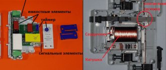
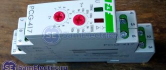
Most devices of this type are designed for mounting in electrical cabinets of protected equipment. The housing is equipped with a latch for mounting on a DIN rail. There are controls on the front for setting response limits.
The operating principle of the device is based on continuous monitoring of the network status. If the voltage or angle between phases goes beyond a critical level, the protective device will generate a shutdown signal and put the equipment out of operation. The shutdown occurs with a time delay. Its value is also adjustable.
Causes of neutral wire breakage
The main reasons for neutral breakage are deterioration of electrical networks and the lack of professionalism of some would-be electricians, who allow wiring to be installed without adhering to the necessary rules. Don't trust non-professionals!
In order to find a break in the neutral in the apartment, you need to inspect all the connections in the panel. It is not difficult to see and fix such a problem. It's another matter if the wire burnt out somewhere in the wall. To find the damaged area under the finish, you must use special testers.
If the neutral wire burns out on the riser at the entrance, then this problem must be solved by electricians from a special service. The task of the apartment owner is to ensure the electrical safety of his own home.
Types of RKF
Different RKF models have different technical characteristics. Therefore, each of these devices belongs to one type or another.
According to the settings options, relays are divided into 2 categories:
- Adjustable. It is possible to set the required response setting for voltage and time (EL-11, EL-12, EL-13, EL-15).
- Unregulated. Only factory settings are supported. An example of such a device is E-511.
Relay EL-13E
Automatic restart
Automatic reclosure (AR) is triggered upon disconnection of the explosive from the protection. It is possible to select protections, upon activation of which the automatic reclosure is triggered.
The automatic reclosure function is implemented with one/two cycles of operation (optional) without controls.
Automatic reclosing is prohibited when:
- when the breaker failure function is triggered;
- manual disconnection from the switch control key;
- the presence of a discrete signal “Recloser prohibition” from the circuits of the existing breaker failure;
- manual activation for a fixed time;
- switch malfunction.
Main technical parameters
Protective devices are used in a wide range of equipment. Therefore, their parameters can differ markedly depending on operating conditions. Of the most important technical characteristics of the phase control relay, the following are noted:
- operating voltage;
- response adjustment limits;
- response delay time;
- Operating temperature range;
- storage conditions.
Supply voltage
This parameter is selected depending on the supply voltage of the protected equipment. If it operates from 380 V, then a relay with a similar voltage value is selected. In addition, RKFs for 110 and 220 V linear voltage are common.
Important! Line voltage is the potential between phase wires. Usually it is 380 V. The phase voltage is between the phase wire and the neutral. Usually this is 220 V, like in an apartment socket.
Phase control unit for maximum line voltage 250V
RKF settings limits
Different phase control relays have different adjustment limits. If the equipment is designed to work with precise parameters of the supply voltage, then you can choose a relay with a narrow control range of 0.9-1.1 Un, which is suitable, for example, for electric motors.
If the accuracy of the supply voltage is not important, then a relay with a range of 0.7-1.3 Un is suitable. Such protective devices are suitable for three-phase heating devices and heating elements.
On/off delay
Many industrial consumers of electricity have a nonlinear starting characteristic. At the moment the engine or heating element is turned on, the starting current is tens of times higher than the rated current. Accordingly, the voltage drops during startup.
To prevent RKF from turning off the network when the voltage drops, an operation delay has been added to its operating algorithm. When the engine starts, the voltage drops below the permissible level, but the relay does not turn off the power for some time. This parameter can be adjusted using the control on the front panel of the device.
Working temperature
Extreme heat or cold has a detrimental effect on the electronic circuit of the RKF. An abnormal temperature value can lead to a drift in the characteristics of the internal radio components of the device, which will provoke its false alarms and shutdowns. Also, sudden cooling can cause condensation of water vapor inside the device, which will damage it. Therefore, it is important to observe the temperature regime of the RKF.
For example, devices of the EL-11E, EL-12E and EL-13E series are capable of operating at temperatures from –40 to +80°C. Therefore, they can be used in conditions of not too frosty winters.
Storage requirements
Every electronic device has both operating and storage conditions. Usually they are similar. Any phase control relay must be stored in its original packaging. If possible, avoid exposing the device to humid environments or extreme temperatures. During storage, vibration and unnecessary transportation of the relay should be avoided.
What is alternating current
Standard three-phase input:
In order to understand the need for 3 phases of power supply and corresponding protection on the lines, we will first analyze what specific current we are talking about. Unlike direct current, the movement of electrons in each alternating current line occurs in accordance with the sinusoidal field voltage. At the moment when it reaches its peak, the movement of particles is maximum in the channel towards the neutral or phase wire with the current zero index. The latter becomes like this during the period when the field power in it is equal to “0”. Then the force that moves the electrons of its sign changes polarity and continues to move particles with the opposite charge in the channel.
This periodic movement of electrons is the essence of the concept of alternating current. Its advantages compared to permanent:
- The line load is not constant, which means the energy transmission channels can be made physically thinner relative to those used during continuous movement of electrons.
- The possibility of economically transmitting current over long distances by raising its voltage with simple transformers at the beginning of the path and then reducing it to operating characteristics using the same devices located on the receiving side.
- The creation of a circular magnetic field is simplified, which makes it possible to simplify the design of electric motors.
- Obtaining two operating voltages in three-phase devices.
- With symmetrical characteristics on all three lines, the end consumer using them for their power supply does not need a separate neutral. The incoming alternating current is enough for him. Of course, with appropriate connection of lines and load.
Review of popular phase control relays
There are dozens of models from domestic and foreign manufacturers on the market. Each of them has its own features and technical characteristics. When choosing an RKF, you need to take into account who produces it and for what purposes.
Zamel CKM 01
Three-phase phase rotation control relay with DIN rail mounting. Has a compact size. The width is standard for 1 module and is 17.5 mm. More detailed characteristics are shown in the table.
| Supply voltage | Single-phase 220 or two-phase 380 V |
| Maximum permissible voltage for contacts | 250 V |
| Internal relay power limit | 2.5 kVA |
| Output contacts | 1NO and 1NC |
| Maximum switching current | 10 A |
| Own consumption | 34 mA |
| Class of housing protection against dust and moisture | IP 20 |
| dimensions | 9x17.5x6.6 cm |
Zamel CKM 01 device for DIN rail mounting
RNPP 311
Relay from domestic. Installed in a panel on a DIN rail. It has a minimum of adjustment controls on the front panel, which makes it suitable for service even by untrained personnel.
| Rated supply voltage | 380 V |
| Mains frequency | 45-55 Hz |
| Own current consumption | No more than 35 mA |
| Voltage regulation range | 1.05-1.25Umax (for Umin similar values) |
| Fixed shutdown delay | 12 sec |
| Starter coil voltage | 110-380 V |
| Critical supply voltage values | 80-500 V |
| Working temperature | –25 +40°C |
| Climatic performance | UHL4 |
| Number of switching cycles at 5 A load | At least 100 thousand times |
Voltage monitor RNPP-311
ABB 1SVR750488R8300
ABB specializes in high-quality electrical equipment. The quality matches the price. The relay in question costs about 11 thousand.
| Control supply voltage | 450 V |
| Operating frequency | 50-60 Hz |
| On/off delay | 0.1-30 sec |
| Number of switching (changeover) contacts | 2 |
| dimensions | 85.6x45x104.8 mm |
OMRON K8AB
A compact device that has a slightly different purpose than the usual RKF. OMRON K8AB does not control voltage, but current. Therefore, an additional current transformer is required for its operation. The manufacturer positions the device as an ideal tool for monitoring current in industrial heaters and electric motors.
| Supply voltage (depending on modification) | 24 AC/DC current or 100-115 V or 200-230 V |
| Controlled current | 2 mA– 200 A |
| Number of controlled phases | 1 |
| Maximum output relay current | 6 A |
| Actuation hysteresis | 5-50 % |
| Model of the current transformer required for operation of the relay | K8AC-CT200L |
Important! Hysteresis, in simple terms, is a switching delay. It allows you to turn the relay on and off at different current values. This is necessary to prevent excessive switching and mechanical wear of the contacts. For example, the relay turns off at 5 A and turns on at 4. Or the temperature controller turns off the heater when the room is 24°C and turns on when 18°C.
Carlo Gavazzi DPC01
Multifunctional three-phase RKF with an expanded list of adjustments. Relays from this manufacturer are found in industrial compressor equipment. The front panel has standard voltage and delay regulators. As well as indicator LEDs, which facilitates human interaction with the device.
| Supply voltage | 24 V DC current or 230 alternating |
| Output current limit | 8 A |
| Adjusting the response delay | From 0.1 to 30 sec |
| Trigger voltage adjustment range | 2-22% of nominal value |
| Number of controlled phases | 3 |
| Degree of protection against dust and moisture | IP 20 |
| Installation | DIN rail |
| Limit voltage for output relay contacts | 550 V |
Euroautomatika FiF CKF-318-1
Belarusian phase control relay, which has proven itself as a simple, cheap and reliable solution for protecting electric motors. This RKF is triggered by a critical decrease/excess of voltage and the loss of one or more supply phases. Characteristics in the table.
| Operating voltage | 220/380 V |
| Output relay current limit | 8 A at 250 V |
| Contact type | 2NO and 2NC |
| Alarm indicator color | Red |
| Voltage lower limit range | 150-210 V |
| Upper voltage limit range | 240-280 V |
| Hysteresis | 5 V |
| Power consumption from the network | 1.6 W |
Relay for monitoring presence and phase rotation F&F CKF-318-1
The key to the security of your electrical network
Today, in the context of the incredibly rapid development of the technical potential of civilized countries, electrical appliances are beginning to play an increasingly important role in their existence.
There is probably no house in which there is not at least one device that uses electricity as an energy source. Separate and unchanged throughout the history of the existence of controlled electricity was the question of the safety of its use. Power outages and surges in the network have created many problems for firefighters over the past two centuries. Over time, humanity has found an effective means of minimizing the risk of using electricity in domestic conditions. This means was the use of voltage relays in electrical circuits. This device instantly responds to changes in voltage in the circuit, preventing fire and equipment breakdown. At the moment, there are probably no electrical appliances that do not use a voltage relay. It consists of two main parts - an electrical circuit disconnector and a voltage regulator installed directly into the relay itself. The latter is produced on the basis of a microprocessor or, in a more primitive design, on the basis of a comparator. The voltage relay, created on the basis of a microprocessor, has the ability to smoothly adjust the response values.
The main requirement that determines the quality of a relay is its response speed. The most modern ones operate almost instantly, down to milliseconds. After the network has been de-energized and the voltage control relay has ensured the power supply is within acceptable limits, the supply of electric current is resumed. This occurs after a pre-programmed period of time. When critical emergency situations occur, it is the voltage relay that becomes the main guarantor of their elimination.
To avoid unpleasant cases of relay malfunction, you should purchase them in branded stores like ABC Electro https://avselectro-msk.ru/catalog/4192-rele
You can immediately select relays according to the prices and parameters you are interested in, covering the entire range at once
They can be produced in the form of extension cords, splitters, tees, and also in the form of a module with a plug and socket - depending on the method of connecting the electrical appliance.
The module is installed directly into the socket. The module's microcontroller monitors the voltage status in the electrical network, projecting data onto a digital display. If necessary, the electromagnetic relay interrupts the current supply. Setting the relay response values and determining the delay time is done using special buttons on the module.
Extension cords, tees, splitters and other devices that serve to distribute the flow of power between several electrical appliances are designed basically similarly to the previously described modules, except that the device contains several sockets, which can be turned off simultaneously if necessary.
If the whole house is to be protected from power surges, the voltage relay is installed in the distribution cabinet. Using its functional and design features, this type of relay has the ability to operate in various modes independent of each other.
The principle of operation of the relay is simple: the circuit voltage, which is within the lower operating threshold, is compensated by the contacts of the relay itself. As soon as the voltage exceeds the specified values, a special magnetic initiator interrupts the circuit.
Pros and cons of domestic relays
Equipment developers and adjusters periodically have to choose between domestic and foreign automation manufacturers. On the one hand, you want to do everything cheaper, and on the other, more reliable. To make the right choice, you need to consider the pros and cons of each option.
Advantages of Russian control relays:
- Low price. Imported RKFs cost at least 2 times more.
- The device can operate at temperatures below –25°C. Among foreigners, such endurance is less common.
- Russian EL series relays do not require additional 24 V power supply. Most foreign relays require an additional voltage source.
Devices produced by the Electrical Engineering Company Meander
Disadvantages of Russian RKFs:
- High heat dissipation. This indicates unreliability of power contacts or high consumption of auxiliary current.
- Incorrect operation of RKF analog circuits. Sensitivity to external interference.
- Outdated appearance. Although in the last decade there has been a “thaw” in terms of the design of domestic automation.
Breaker failure redundancy (CBF)
The breaker failure function starts when the shutdown protection is triggered. The start of the cyclogram corresponds to the moment the shutdown command is removed, the duration of which is 2T of the nameplate shutdown. Breaker failure is determined by the currents of phases A, B and C.
The time cyclogram of the formation of the output signal “Operation of Breaker Failure” is shown in Fig. 1.
Rice. 1.
High voltage circuit breaker control
Disabling the high-voltage circuit breaker is provided in the following cases:
- when your own protections are triggered;
- in the presence of an external shutdown signal;
- in the presence of a signal from an external breaker failure;
- when manually disconnecting the high-voltage switch from the control key.
The execution of the “OFF” command is controlled by the state of the block contacts of the switch “On”, “Off” and by the disappearance of input phase currents. The duration of the shutdown command is equal to twice the certified shutdown time of the circuit breaker, specified in the operational parameters of the PM RZA.
When the circuit breaker is switched off by the protections or when the protections are operating “on a signal”, a discrete output signal of the PM RPA “Operation of protections” is generated.
Turning on the switch is provided:
- in the automatic reclosure cycle
- when there is a switching command from the switch control key.
The switching command is issued to a working switch when the grounding blade is open.
The execution of the “ON” command is controlled by the state of the switch block contacts. The duration of the switching command is equal to twice the nominal switching time of the switch.
When the trolley is rolled in and out with the switch on, the switch turns off without a time delay.
The possibility of repeatedly turning on the switch due to a short circuit is excluded.
Circuit design
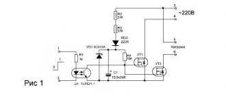
Within reasonable limits, the RKF connection diagram depends on the developer’s imagination. The standard device has 3 inputs for connecting phases. They are usually located at the top of the device. At the bottom there is a terminal block with 4 pins - NO and NC relay contacts. Some actuator is connected to them. For example, a more powerful relay, contactor or magnetic starter. It is possible to connect the load directly, but you need to take into account the current it consumes.
Relay design elements
Old Soviet relays for monitoring open-circuit and phase rotation were fixed to the mounting location using 2 screws. Modern devices are equipped with DIN rail mounting. This approach simplifies the repair and development of electrical cabinets.
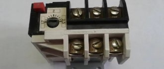
The second design feature of the phase control relay is screw terminal blocks for connecting wires. The vast majority of protection devices are equipped with such contacts.
Adjustable controls
Regulators for setting the relay operating parameters are located on the front panel. This allows you to make changes without removing the device itself from the electrical panel. The regulators are made on the basis of trimming resistors. They do not stick out from the surface of the device. To rotate them, you must use any suitable screwdriver.
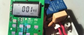
Some models of network imbalance protection relays are equipped with buttons and a display. In such devices, nothing needs to be rotated. However, it is somewhat more difficult to understand what is regulated and how. Especially without a user manual.
Electronic control device
Pin assignment markings
In terms of marking and designation of terminals, everything is the same as on any modern devices. The letters on the device body have the following designations:
- L1, L2, L3 - terminals for connecting 3 phases of the controlled network;
- NO/NC — output relay contacts;
- Umax is the maximum voltage threshold at which RKF will turn off the protected equipment;
- Umin - respectively, the minimum shutdown threshold;
- delay - the time after which the relay will operate.
Note! NC/NO (normal closed / normal open) - normally closed/open relay contacts. This marking is used on all modern equipment. The NC contacts are in a closed state and are short-circuited with a multimeter if voltage is not applied to the relay coil. As if it was just lying on the table. NO - opposite contacts. Without voltage they are in an open state.
What is a zero break in a three-phase network - causes and protection
Zero break protection
There are two main ways to protect against a zero break: re-grounding the neutral conductor and installing a voltage relay:
1) Re-grounding of the zero - this method of protection is suitable for private residential buildings, the grounding of which is carried out using the TN-CS system, while in the incoming electrical panel of the house a ground loop is connected to the neutral conductor:
As can be seen in the diagram, when the zero breaks (burns out), the equalizing current continues to flow to the ground loop, due to which the phase voltage is maintained at 220 Volts. For more information on how to re-ground, read the article: Grounding in a private house.
2) Installation of a voltage relay - this method is used to protect the electrical network of apartments in multi-apartment buildings from a zero break, as well as to protect the electrical network of private residential buildings with grounding carried out according to the TT system, or without a ground loop at all.
A voltage relay is a device that monitors the voltage level of the electrical network; if it increases or decreases to an unacceptable level, the voltage relay turns off the electrical network until the network voltage returns to normal.
Was this article useful to you? Or maybe you still have questions ? Write in the comments!
Didn’t find an article on the website on a topic that interests you regarding electrical engineering? Write to us here. We will definitely answer you.
Bottom line
At any industrial enterprise there are hundreds and thousands of three-phase asynchronous motors. No matter how modern and reliable the motor is, if during operation one of the phases feeding it disappears, it will burn out. The cost of the largest and most powerful engines is comparable to the price of a good car. A control relay costs much less than a motor. But it will definitely save him in the event of a phase failure. This explains the economic feasibility of installing RKF for engine protection.
Voltage quality is important not only for asynchronous machines. When there is a short circuit in the line, the voltage in one of the phases drops to almost zero. This mode of operation is unacceptable. RKF will notice a critical voltage imbalance and turn off the line. Thus, all consumers will be protected from abnormal operating conditions and subsequent losses.
With this in mind, the RKF is far from the least important protective device. It has not lost any relevance since Soviet times. On the contrary, with the development and complexity of equipment, the relay is only becoming more in demand, because it allows you to protect expensive electrical machines from breakdown.
A Question of Choice
The main characteristics that are recommended to be followed when choosing a phase control relay:
- Response speed.
- Availability of a time relay for turn-on and cut-off delay.
- Setting parameters manually and the breadth of their setting. The latter will tell you better than any documentation about the sensitivity of the protection device.
- Functional completeness, expressed in the control of distortions, voltages, directions and breaks of phase lines and/or neutral.
- Mounting chassis. Some models are designed for installation into a standard DIN rail for a classic panel, others are attached directly to flat surfaces. It is not uncommon to combine different clamps in one housing.
Mounted phase control relay in a standard panel:
The secondary selection condition can be called the protection class of the device - its IP index. But it is only important when using a circuit breaker without an additional housing, when installed directly on the street.
What is it for?
Application of phase voltage monitoring relay
Special phase controllers are in demand in places where it is necessary to frequently connect to the power supply and where it is important to observe their alternation. As an example, the situation is usually considered when the connected equipment is constantly transferred from one place to another. In this case, the probability of mixing up the phases of linear voltages is very high
In this case, the probability of mixing up the phases of linear voltages is very high.
In some loads, incorrect alternation of them can lead to improper operation of the device and subsequent breakdown. Any unit connected to such a network for a long time is likely to fail. When operating such a device, you can easily make a mistake in assessing its condition, believing that the device needs repair.
