To ensure the safe operation of electrical equipment, a variety of electronic devices and other devices are used. They are designed to monitor the standard operating parameters of electrical installations, and in case of emergency situations to turn them off. A prominent representative of such devices is an electrothermal relay, which disconnects the electrical installation from the supply electrical network in the event of a prolonged excess of the rated operating current. A thermal relay is an automatic shutdown of a device that consumes electricity in case of serious overload of the equipment in terms of power supply current.
Areas of use of the device
Electrothermal relays are designed to prevent failure of electric motors from overloads in terms of operating current, which results in exceeding the standard operating temperature of the latter. Any electric motor has a rated operating current. A critical excess of this technical characteristic for a long time will lead to overheating of the windings of the power plant, destruction of the insulating layer and failure of the motor as a whole.
The electrothermal protection device will turn off the electric motor and prevent an accident and failure of the electric motor. Thermal overload protection relays are also used in other areas of the national economy, everyday life and production, but their main purpose is to protect electrical power plants from increasing load current to critical values. Without this device it is impossible to operate electric motors safely!
Smart search
The choice of a thermal relay must follow the rules. The operating current rating is taken as the basis. Moreover, the standards, both domestic and international, imply that the minimum will be similar to that established for the protection to operate.
This provides for activation of the device only when the line is overloaded by 20-30%. But no later than 20 minutes. That is, in order to avoid false switching on, the starting parameters must be 12% higher than the nominal ones.
Overheat protection Source prom.st
And if there is an asynchronous motor with a power of 1.5 kW, connected to a 380 V network, then a relay with a threshold current of 3.36 Amperes is suitable for it. Because the operating rating of such a motor is 2.8 A. And if you look at the tables in special reference books, then the RTL-1008 thermal relay operates in the range from 2.4 to 4.0 Amperes.
If the motor data is unknown, it is necessary to measure the current at each phase of the line. To do this, use either a current clamp or a multimeter. It is important to pay attention to the voltage at which the relay operates. And installation into a network with three phases must be done through an additional module that protects against phase imbalance.
Design and principle of operation of the device
The reliability of power plants directly depends on the various overloads to which the device is subjected during operation. For each device, there are current limit values and their duration, at which the equipment operates in normal and safe mode. At rated current values, the duration of operation of an electric motor or any other electrical installation is limited only by the mechanical strength of the rotating parts. If this value is exceeded for a long time, an emergency situation occurs.
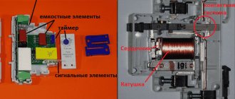
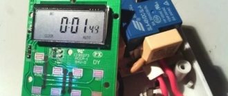
To ensure protection of electric motors and other equipment from overloads, devices with bimetallic elements are widely used. These devices operate in accordance with the law of physics, described by scientists Joule and Lenze in the 19th century, which determines the dependence of the heat generated on the current strength in a specific section of the electrical circuit. It is this law that is decisive in the operation of an electrothermal relay (release). The design of the device includes a spiral, which is a heat emitter. A bimetallic plate is mounted directly next to it, reacting to the radiated heat.
Thermoplates are made of two metal alloys with different thermal conductivities, which change their geometry when heated/cooled. This property of bimetallic elements is incorporated into the operating principle of the thermal release. With any increase or decrease in the load current, the working plates change their spatial arrangement and mechanically act on the pusher, which opens or closes the contact groups of the thermal relay connected to the windings of the magnetic starter (MP). The motor starter operates and disconnects the load from the electrical network. The standard design of an electrothermal relay is shown in the following picture.
The operation of thermal releases with bimetallic plates is affected by the ambient temperature, additionally heating the working elements of the device design. To eliminate this phenomenon, all devices of this type are equipped with additional compensating bimetallic plates that bend in the opposite direction relative to the main elements.
The compensator is a regulator of the operating current of the device. For adjustment, an eccentric with a scale divided into two parts is used. When the compensator handle is turned to the left, the operating current value decreases, and when shifted to the right it increases accordingly. The release current values are adjusted by increasing/decreasing the gap between the pusher and the main plate, due to the action of the eccentric on the additional bimetallic plate.
Important! When one of the power phases breaks or is disconnected in a three-phase network, the load current in the remaining two phases increases, which leads to the operation of the electrothermal relay. Based on this, we can say that the thermal release protects the electric motor from operation in an emergency situation with a broken phase.
Why are protective devices needed?
Even if the electric drive is properly designed and used without violating the basic operating rules, there is always the possibility of malfunctions.
Emergency operating modes include single-phase and multi-phase short circuits, thermal overloads of electrical equipment, jamming of the rotor and destruction of the bearing unit, phase loss.
When operating under high loads, an electric motor consumes a huge amount of electricity. And when the rated voltage is regularly exceeded, the equipment heats up intensely.
As a result, the insulation quickly wears out, which leads to a significant reduction in the service life of electromechanical installations. To eliminate such situations, a thermal protection relay is connected to the electric current circuit. Their main function is to ensure normal operation of consumers.
They turn off the motor with a certain time delay, and in some cases instantly, to prevent destruction of insulation or damage to individual parts of the electrical installation.
The current relay constantly protects the electric motor from phase failure and technological overloads, as well as rotor braking. These are the main reasons why emergency situations occur
In order to prevent a decrease in insulation resistance, protective shutdown devices are used, but if the task is to prevent cooling failure, special devices with built-in thermal protection are connected.
Types of thermal protection relays
It should be noted that on the modern market of electrical products there are different types of thermal protection modules for electric power units. Each of these types of devices is used in a specific situation and for a specific type of electrical equipment. The main types of thermal protection relays include the following designs.
- RTL — an electromechanical device that provides high-quality thermal protection of three-phase electric motors and other power plants from critical overloads in current consumption. In addition, a thermal relay of this type protects the electrical installation in the event of an imbalance in the supply phases, a delayed start-up of the device, as well as in case of mechanical problems with the rotor: shaft jamming and so on. The device is mounted on PML contacts (magnetic starter) or as an independent element with a KRL terminal block.
- PTT — a three-phase device designed to provide protection for electric motors with a squirrel-cage rotor from current overloads, imbalance between supply phases and mechanical damage to the rotor, as well as from prolonged starting torque. It has two installation options: as an independent device on a panel or combined with magnetic starters PME and PMA.
- RTI — a three-phase version of an electrothermal release that protects the electric motor from thermal damage to the windings when current consumption values are critically exceeded, from a long starting torque, asymmetry of the supply phases and from mechanical damage to the moving parts of the rotor. The device is installed on magnetic contactors KMT or KMI.
- TRN — a two-phase device for electrothermal protection of electric motors, providing control of the start duration and current in normal operating mode. Returning contacts to their original state after an emergency operation can only be done manually. The operation of this release is completely independent of the ambient temperature, which is important for hot climates and hot industries.
- RTK - an electrothermal release, with which you can control a single parameter - the temperature of the metal casing of the electrical installation. Control is carried out using a special probe. If the critical temperature value is exceeded, the device disconnects the electrical installation from the power line.
- Solid State - a thermal relay that does not have any moving elements in its design. The operation of the release does not depend on the temperature in the environment and other characteristics of the atmospheric air, which is important for explosive industries. Provides control over the duration of acceleration of electric motors, optimal load current, breakage of phase wires and jamming of the rotor.
- RTE - a protective thermal relay, which is essentially a fuse. The device is made of a metal alloy with a low melting point, which melts at critical temperatures and breaks the circuit that powers the electrical installation. This electrical product is mounted directly into the housing of the electric power plant in a standard place.
From the above information, it can be seen that there are currently several different types of electrothermal relays. All of them are used to solve one single problem - protecting electric motors and other power electrical installations from current overloads with an increase in the temperature of the working parts of the units to critical values.
Briefly about the main thing
The thermal relay is an essential element for protecting the electric motor when operating under continuous peak overloads. During operation, the motor is constantly exposed to influences that impede its operation. Most often, such influences are short-term in nature.
But since any excess load provokes an increase in the temperature of various components, this can lead to serious damage. If an increase in current operates in the network for too long, it easily leads to either burnout of the winding or jamming of the motor shaft.
The thermal relay is the most reliable protection. Ignoring short-term failures, the device only responds to long-term problems. Completely eliminating unwanted overheating of equipment.
Where can I buy
You can purchase the device as quickly as possible at your nearest specialty store. The optimal option, in terms of price-quality ratio, remains purchasing from the AliExpress online store. Mandatory long waits for parcels from China are a thing of the past, because now many goods are in intermediate warehouses in destination countries: for example, when ordering, you can select the “Delivery from the Russian Federation” option:
| Thermal relay LRD06 | Thermal overload relay, 3 contacts | Thermal relay JRS1-25 |
| Thermal overload relay 16/22/32A | Thermal relay JRS1-40-80, 80A | Thermal overload relay JR36-20 |
Examination
Let's look at the example of a TRN type relay. To make sure the relay is working properly:
- Check the condition of the case to see if there are cracks or chips on it.
- Check with a connected load with rated current.
- Disassemble the relay and check the integrity of the contacts, the absence of carbon deposits on them,
- Check if the heaters are bent.
- Check the distance between the bimetal and the heating elements. It should be the same, if not, then adjust using the mounting screws.
- Apply rated current through one of the heaters, set to 1.5 times the rated current. In this state, the relay operates for 145 s, then the adjustment eccentric is gradually turned to the “-5” position until the relay operates.
After active cooling for 15 minutes, check the second heating element in the same way.
Thermal relay connection diagram
Most often, the thermal relay is connected directly to the magnetic starter. The power contacts of the device allow it to be installed on the MP wirelessly. There are also thermal protection models that can be installed as a separate module on a mounting panel or DIN rail in an electrical cabinet. The following figure shows a block diagram of connecting a thermal relay in accordance with current GOST.
The following figure shows a control diagram for an electric motor that disconnects it from the network in the event of an emergency: current overload or wire break in one of the phases.
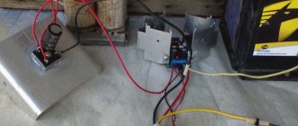
For an uninitiated person, all these circuit diagrams mean absolutely nothing, so the next picture will show a wiring diagram for an electrothermal relay that is more accessible to the common consumer, with photographs of all the elements included in the system for protecting electric motors from current overloads.
Let's briefly look at how this motor protection arrangement works. The input machine provides the supply of one phase through the normally closed emergency “Stop” button to the open “Start” button. When it is turned on, the supply voltage is applied to the winding of the magnetic starter, which turns on the electric motor in series. All phases of the power supply network supplied to the electric motor pass through relay windings with bimetallic elements. If the load current increases to maximum values, the thermal protection is triggered and the power plant is de-energized.
Attention! An electrothermal relay is installed in the power circuit after all types of contactors, but before the electric motor or other electrical equipment. The circuit-breaking device is turned on using the “Stop” button. All elements of the protection system are connected in series.
Summary
Diagrams that depict the principle of connecting a relay to a contactor may have other letter or digital designations. Most often, their decoding is given below, but the principle always remains the same. You can practice a little by assembling the entire circuit with a consumer in the form of a light bulb or a small motor. Using the test key, you can work out a non-standard situation. The start and stop keys will allow you to check the functionality of the entire circuit. In this case, it is necessary to take into account the type of starter and the normal state of its contacts. If there are any doubts, then it is better to consult an electrician who has experience in assembling such circuits.
Recommended Posts
Connection diagrams for 380 V electric motors
Security alarms for home and garden
DIY installation and connection of the lamp
How to replace a light bulb
LED chandeliers with remote control: reviews
Which is better - LED or energy-saving lamp
Selecting an electrothermal relay
The choice of thermal relay depends on many factors of its operation: ambient temperature; where it is installed; power of connected equipment; necessary emergency warning means, and so on. Most often, the consumer makes a choice based on the following technical characteristics of the device.
- For single-phase networks, you should choose a thermal relay with an auto-reset function and return the contacts to their original state after a certain period of time. Such a device will re-work if the emergency situation persists and the equipment current overload continues to be present.
- For hot climates and hot workshops, thermal relays with an air temperature compensator should be used. These include models with the designation TRV. They are able to function normally in a wide range of external temperatures.
- For equipment critical to phase failure, appropriate thermal protection should be used. Almost all thermal relay models are capable of shutting down electrical installations in the event of such a situation, since the failure of one phase sharply increases the load current on the remaining two.
- Thermal relays with light indication are most often used in industry, where it is necessary to quickly respond to an emergency situation. LED device status sensors allow the operator to visually monitor the work process.
The price of a thermal protection relay can fluctuate over a very wide range. The cost of the device depends on many factors: general technical characteristics, the presence of additional functions used in the production of materials, as well as the popularity of the device manufacturer. The minimum price of a thermal relay is about 500 rubles, and the maximum can reach several thousand. Relays from well-known manufacturers are necessarily equipped with a passport with a detailed description of the technical characteristics, as well as complete instructions for connecting the device to electrical installations.
Specifications
Correct operation of relay protection is ensured by matching the parameters of the thermal device to the specified operating conditions of the electrical machine. Therefore, it is important to study the basic operating parameters of the relay before purchasing it. The main technical data of the thermal relay include:
- the rated voltage value and frequency for which it is designed;
- time-current characteristic – determines the response time at a set excess factor;
- time for the thermal element to return to its original position;
- setting current change range;
- thermal resistance to exceeding the operating value;
- climatic design and degree of dust and moisture protection.
Advantages of the device
At its core, a thermal relay is an automatic device for disconnecting electrical equipment from the power supply. But unlike a simple on/off automatic switch, an electrothermal relay has the following significant advantages:
- the ability to adjust the time and moment of operation depending on the overload current and the duration of its effect on electrical equipment;
- different switching options: remote installation in electrical panels or direct installation on magnetic starters.
Other advantages of thermal relays include small size, weight and, of course, cost, as well as simplicity of design and high operational reliability. A certain disadvantage of the device is the need for periodic adjustments and verifications.
Symbol
On an electrical diagram, a relay is usually denoted by a rectangle, from the large sides of which lines of solenoid power terminals extend.
Graphic markers
Relay symbols on diagrams
The graphical method of depicting elements is implemented using geometric shapes:
- contacts – similar to switch contacts;
- devices with contacts near the coil - dashed line connection;
- contacts in different places - serial number next to the rectangle;
- polar relay - a rectangle with two terminals and a dot near the connector;
Relay contact group - fixation of the switch when triggered - a bold dot at the fixed contact;
- closed relay contacts after the voltage has been removed - a circle is drawn on the designation of a closed or open contact;
- magnetically controlled contacts (reed switch) in the housing - circle;
- number of windings – inclined lines;
- moving contact – arrow;
- single-line conductive surface - a straight line with branch terminals;
Polarized relay - annular or cylindrical current-carrying surface - circle;
- jumpers (relay as a voltage divider) for cutting the network - a line with detachable connection symbols;
- switching jumper – U-shaped bracket.
Relay contacts can be signed.
Letter designation
A UGO relay is sometimes not enough to correctly read the circuit. In this case, a letter marking method is used. The relay code is the English letter K. For a clear understanding of what a letter on a relay diagram can mean, you should refer to the table.
| Letters | Decoding |
| A.K. | Block relay/protective complex |
| AKZ | Resistance relay kit |
| K.A. | Current relay |
| KAT | R. current with BNT |
| KAW | R. current with braking |
| KAZ | Current relay with filter functions |
| K.B. | R. lock |
| KF | R. frequencies |
| KH | Index |
| KL | Intermediate |
| F | Fuse |
| XN | Permanent connection |
| XT | Separable connection |
| KQC | Relay "on" |
| KQT | Relay "off" |
| KT | R. time |
| KSG | Thermal |
| KV | R. voltage |
| K 2.1, K 2.2, K 2.3 | Contact groups |
| XT | Terminals |
| E | Elements to which the relay is connected |
| NO | Normally open contacts |
| NC | Normally closed contacts |
| COM | General (switching) contacts |
| mW | Power consumption |
| mV | Sensitivity |
| Ω | Winding resistance |
| V | Voltage rating |
| mA | Rated current |
Letters can be used on a graphic diagram.