Home / Support / Load cell diagnostics
Carefully check the general technical condition of the weight measurement system:
- presence of a grounding loop (shunt), tightening of threaded connections;
- checking the absence of traces of corrosion, damage to strain gauges, installation units, and load receptors;
- checking summing boards; weight indicator on the strain gauge simulator;
- testing the weight indicator, connecting to the strain gauge simulator;
- inspection of the condition of cable products, tightness of the cable entry on the strain gauge;
To perform diagnostics you will need:
HY-LCT tester - with this device it is possible to perform all the necessary measurements.
In the absence of specialized equipment for testing strain gauges, it can be done using the following devices:
- A volt-ohmmeter with a measurement limit of ≤0.5Ω and ≤0.1 mV (in extreme cases, a high-quality multimeter) to measure the zero balance and the integrity of the strain gauge bridge;
- Megger 1000 MOhm no more than 50V DC, for measuring insulation resistance;
- A lifting device (jack, crane, etc.) necessary to lift the load receptor and release the load cell from the load;
- Prepare a table to record the values taken during measurement;
To identify a faulty load cell, it is sufficient to carry out 4 main types of tests. Let's look at the sequence of their implementation and why they are needed:
1) Checking the insulation resistance.
To perform this test, you must connect a megger to the load cell cable and check for leakage current between the load cell body and live parts. To test Keli strain gauge circuits, it is allowed to use a megger with a voltage of no more than 50V DC.
For a functioning strain gauge, the value of the measurements taken should not be lower than 5 MΩ. If the insulation resistance value is less than 1 kOhm, this indicates an obvious short circuit. A short circuit can occur between the strain gauge housing and live parts (strain gauges), as well as in the cable. If there is a short circuit in the cable, it can be replaced if the design of the strain gauge allows for this.
2) Checking the strain gauge bridge - Wheatstone.
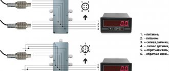
The absence of damage to the bridge is verified by measuring the input and output resistance, as well as the balance resistance of the bridge. Disconnect the sensor from the box or meter. Input (EXC+, EXC-) and output (SIG+, SIG-) resistances are measured with an ohmmeter connected to each pair of input and output wires of the strain gauge. Then the input and output resistance are compared with the values in the calibration passport (issued by the manufacturer) or with technical data from the catalog. The bridge balance resistance is measured by connecting an ohmmeter to each pair of cable terminals in turn. The resistance value between pairs should not differ by more than 1-2 Ohms.
A discrepancy between the input and output resistance of the strain gauge from the nameplate values indicates a malfunction of the strain gauge bridge; as a result, the appearance of unbalance resistance indicates that the strain gauge is inoperable and needs to be replaced. These malfunctions usually arise due to electrical influence (welding, static field, electrical breakdown), physical (dynamic shocks, twisting, lateral loads).
How to check a load cell or diagnose faults in the operation of load cells
The diagnostic parameters of strain gauges indicated in the article refer to products of the VPG group of companies produced under the brands: CELTRON, REVERE TRANSDUCERS, SENSORTRONICS, TEDEA-HUNTLEIGH. When diagnosing strain gauges from other manufacturers, you should use the testing parameters specified in the technical data sheet of the strain gauge being tested.
Load cells are designed to sense force or weight under a wide range of adverse conditions. They are not only the most important part of the electronic weighing system, but also the most vulnerable. Possible causes of failure of strain gauges: - overload - lightning - power surges - exposure to chemicals or moisture - improper installation - vibrations - shock loads These reasons can lead to zero drift, unstable data transmission or no data transmission at all. Trimming the length of the standard strain gauge cable leads to a decrease in the accuracy of readings, since its resistance is taken into account in the total resistance specified in the strain gauge data sheet.
This article examines typical problems during the operation of strain gauges and testing methods to identify points of failure of a complex of weighing equipment.
Carefully check the integrity of the weighing system: • Check the system for shorts (may be caused by contamination, mechanical damage) • Check for damage, corrosion or significant wear on the platform metal structures. • Check cable connections to the junction box and weighing terminal. • Check the functionality and accuracy of the indicator or weighing terminal on a working load cell. Perform a visual inspection of the weighing equipment before performing the tests described below. Particular attention should be paid to signs of corrosion (especially in places where strain gauges are installed), cable integrity (breaks, cuts, entanglements) and the condition of cable entries and connectors.
To test strain gauges, the following equipment is required: • A high-precision, calibrated, digital voltmeter and ohmmeter with measurement accuracy of ±0.1 mV and ±0.5 ohms to measure zero balance and bridge circuit integrity. • Megaohmmeter, with a measurement limit of 5000 MOhm with an accuracy of 500 MOhm at a voltage of 50 volts, for measuring insulation resistance. Do not use megohmmeters with an operating voltage of more than 50 volts to prevent failure of the strain gauge! • A lifting device (crane, hydraulic jack, etc.) will be required to measure zero balance.
For comparison, use the load cell parameters specified in the calibration certificate that comes with each load cell. The calibration certificate specifies the exact values of input and output resistance, insulation resistance, zero balance, load rating and wiring diagram.
Test procedures and analysis
The diagram below shows the suggested sequence of actions when testing a set of weighing equipment. To determine the location of the fault, it is necessary to take measurements on each load cell separately.
Test #1: Zero Balance
The zero point balance is determined at the load cell output in the “no load” state. Therefore, no load should be placed on the load cell (including the weight of the installation kit and the structures of the weighing equipment). To avoid obtaining incorrect results, measurements should be made on a strain gauge mounted in accordance with the installation diagram specified in the technical documentation for it. The strain gauge must be connected to a stabilized power source with a voltage of at least 10V. In systems with several sensors, it is necessary to disconnect the remaining sensors from the circuit during measurements. Measure the voltage at the strain gauge output with a millivoltmeter and divide by the input voltage value and you will get the zero balance value in mV/V. Compare with the value specified in the load cell calibration certificate or in the technical documentation for it. You can find technical documentation from manufacturers on our website on the page of the load cell of your model in the “Documentation” tab. Analysis of results.
Changes in zero balance usually occur if the load cell is constantly subjected to deforming overloads and/or shock loads. Strain gauges whose measured voltage readings change most likely have damage to the strain gauge due to exposure to chemicals or moisture, and therefore damage to the insulation and sealing layer is also likely.
Test #2: Insulation Resistance
Insulation resistance is measured between the electrical circuits of the load cell, the sensor body and the cable shield. Before starting measurements, disconnect the weight indicator from the load cell or the load cell from the distribution box, depending on the connection diagram, then connect together all the inputs and outputs of the load cell. Measure the insulation resistance using a megohmmeter between the connected wires (four or six) and the strain gauge body. Repeat the measurement between the same 4 or 6 pins and the cable shield. Then measure the insulation resistance between the load cell housing and the cable shield. Never use a megohmmeter to measure the input signal or output resistance of a strain gauge because it operates using a voltage value that exceeds the maximum allowable voltage for the strain gauge circuits. Analysis of results.
The insulation resistance of all strain gauges must be at least 5000 MΩ between the strain gauge and the strain gauge body, the strain gauge and the strain gauge body, and the cable shield. If the resistance is below this value, then this is most likely due to the harmful effects of chemicals or moisture on the strain gauge or cable. Extremely low readings (≤1 kΩ) indicate a short circuit rather than moisture. The stability of insulation resistance measurements may also depend on the ambient temperature.
Test #3: Bridge Integrity
The integrity of the bridge is verified by measuring the input and output resistance, as well as the balance of the bridge. Disconnect the load cell from the junction box or weigh terminal. The input and output resistance are measured using an ohmmeter for each pair of input and output signals. Compare the measured value with the value specified in the load cell calibration certificate or in the technical documentation for it. You can find technical documentation for the load cell on our website on the page of the load cell of your model in the “Documentation” tab. The balance of the bridge is obtained by measuring the resistance value between: • negative terminal OUT and negative terminal INPUT • negative terminal OUT and positive terminal INPUT The difference between both measurement values should be less than or equal to 1 ohm. Analysis of results.
Changes in bridge resistance or bridge balance are most often caused by a broken or burnt wire, electrical component failure, or internal short circuit. This most often occurs due to voltage surges (lightning or welding), physical failure from shock loading, vibration or metal fatigue, exposure to high temperature, or the use of incompatible components in the weighing equipment system.
Test #4: Impact Resistance
The load cell must be connected to a stabilized power source with a voltage of at least 10V. In systems with several sensors, it is necessary to disconnect the remaining sensors from the circuit during measurements. Connect a voltmeter to the output wires. Give the load cell a light blow with a small rubber hammer. Be extremely careful not to damage the load cell during impact testing. Monitor the voltmeter readings during the test. The readings should not become erratic or erratic, but should remain reasonably stable and return to the original zero reading. Analysis of results.
Erratic and random readings may indicate a damaged electrical connection or a damaged adhesive layer on the strain gauge.
If you have not found the answer to your question, perhaps it is on the forum on our website.
Universal strain gauge tester LCT-Ultimate
For professional work on diagnostics and testing of strain gauges, we recommend the universal strain gauge tester LCT-Ultimate, which is an autonomous hand-held device that was specially designed for testing and identifying faults of strain gauge elements of strain gauges. A distinctive feature of this tester is the ability to test the strain gauge for metal fatigue.
You may also be interested in articles
:
- Color coding of strain gauge wires
- Load cell electrical circuit diagram with description
Load cells
3) Checking the zero balance (in an unloaded state).
This test is carried out to check the condition of the load cell in an unloaded state; for this, the load cell is removed from the installation unit and all applied load is removed from the load cell. Next, you need to connect the power source recommended by the manufacturer for proper operation of the strain gauge to the excitation circuit of the strain gauge, and remove the signal in mV from the output circuit and compare it with the value specified in the data sheet for the sensor. For Keli Sensing strain gauges, the recommended supply voltage is 5-12V(DC).
Example: with a strain gauge sensitivity of 2mV/V and a power supply of 10V, the zero balance voltage should not exceed +- 0.02 mV.
If the values of the output signal differ significantly from the passport values, one can judge the deformation of the elastic element of the strain gauge; it is also possible that the insulating layer of the strain gauges may come off or be damaged.
What is strain gauge and why are strain gauges needed?
Strain measurement (from the Latin tensus - tense) is a method and technique for measuring the stress-strain state of the measured object or structure. The fact is that it is impossible to directly measure mechanical stress, so the task is to measure the deformation of an object and calculate the stress using special techniques that take into account the physical properties of the material.
The operation of strain gauges is based on the tensoelectric effect - this is the property of solid materials to change their resistance under various deformations. Strain gauges are devices that measure the elastic deformation of a solid and convert its value into an electrical signal. This process occurs when the resistance of the sensor conductor changes when it is stretched and compressed. They are the main element in instruments for measuring the deformation of solid bodies (for example, machine parts, structures, buildings).
4) Checking the load cell in a loaded state.
For this test, the load cell must be connected to a weighing indicator or to a device with a stable power source from 5V to 12V. Using a millivoltmeter connected to the output of the strain gauge, the sensor is loaded and the output signal readings are recorded; when the load is removed, the output signal readings should return to the original ones. When carrying out this test, it is necessary to carry out several cycles of loading and unloading the strain gauge with different weights, but not less than 50% of the sensor’s LEL. It is also necessary to hold the weight for at least 30 minutes. in each cycle and analysis of changes in readings during a given period of time. If during the test the readings differ from the value of the constantly applied load, and also do not return to the original values, it can be judged that the contact in the adhesive layer between the strain gauges and the elastic element is broken. This strain gauge requires replacement.
Load cell calibration:
The calibration process is shown in the video:
Code from video for calibration:
Calibration code
/* Set up your scale and start the sketch WITHOUT a weight on the scale Once readings are displayed place the weight on the scale Press +/- or a/z to adjust the calibration_factor until the output readings match the known weight Arduino pin 6 -> HX711 CLK Arduino pin 5 -> HX711 DOUT Arduino pin 5V -> HX711 VCC Arduino pin GND -> HX711 GND */ #include "HX711.h" HX711 scale(A1, A0); // DT, CLK float calibration_factor = -3.7; // this calibration factor is adjusted according to my load cell float units; float ounces; void setup() { Serial
.begin(9600);
Serial
.println("HX711 calibration sketch");
Serial
.println("Remove all weight from scale");
Serial
.println("After readings begin, place known weight on scale");
Serial
.println("Press + or a to increase calibration factor");
Serial
.println("Press - or z to decrease calibration factor");
scale.set_scale(); scale.tare(); //Reset the scale to 0 long zero_factor = scale.read_average(); //Get a baseline reading Serial
.print("Zero factor: ");
//This can be used to remove the need to store the scale. Useful in permanent scale projects. Serial
.println(zero_factor);
} void loop() { scale.set_scale(calibration_factor); //Adjust to this calibration factor Serial
.print("Reading: ");
units = scale.get_units(), 10; if (units < 0) { units = 0.00; } ounces = units * 0.035274; Serial
.print(ounces);
Serial
.print("grams");
Serial
.print(" calibration_factor: ");
Serial
.print(calibration_factor);
Serial.println
();
if( Serial
.available()) { char temp =
Serial
.read(); if(temp == '+' || temp == 'a') calibration_factor += 1; else if(temp == '-' || temp == 'z') calibration_factor -= 1; } }
Code for scales
#include "HX711.h" HX711 scale(A1, A0); float calibration_factor = -3.7; // calibration! float units; float ounces; void setup() { Serial
.begin(9600);
scale.set_scale(); scale.tare(); //Reset to 0 scale.set_scale(calibration_factor); //Apply calibration } void loop() { Serial
.print("Reading: ");
for(int i = 0;i < 10; i++) units =+ scale.get_units(), 10; // average the readings by counting 10 times units / 10; // divide by 10 ounces = units * 0.035274; // convert ounces to grams Serial
.print(ounces);
// send to the port monitor Serial
.print("grams");
Serial.println
(); }
The unit of weight has been changed in the code, the value in the port monitor is in grams, not in ounces.

