One of the most important aspects of safety, reliability, correct operation of electrical power lines, installations, devices, etc., is high-quality insulation. Many people who are far from electrical engineering issues take it for granted. That is, there is insulation - and it’s nice, it means everything is normal, and you can use electricity without fear. Meanwhile, this is a serious misconception.
Firstly, ideal dielectrics simply do not exist. Secondly, even the most reliable insulation can lose its qualities over time - burn out, melt, crack, begin to crumble, and suffer mechanical damage. Thirdly, its dielectric qualities are also affected by external factors - dampness, air humidity, surface contamination and others.
How to use a megohmmeter
So monitoring the state of insulation is no less important than all other components of electrical installations. No facility can be put into operation until the insulation resistance has been verified to comply with existing standards. And for such control measurements, special devices called megohmmeters (or megohmmeters) are used. In everyday life, owners of houses and apartments rarely encounter them. And many do not even suspect the existence of such control and measuring devices. Meanwhile, one way or another, it is necessary to monitor the condition of your electrical network. Therefore, it seems that information on how to use a megohmmeter will be useful to everyone.
GENERAL OCCUPATIONAL SAFETY REQUIREMENTS
1.1. An employee who is at least 18 years old, who has undergone a medical examination and has no contraindications for health reasons, has the necessary theoretical and practical training, has completed introductory and initial workplace safety briefings and has received permission to work using a megaohmmeter, is allowed to perform work with a megohmmeter. 1.2. When performing work using a megohmmeter, the employee must undergo training and testing of knowledge of the norms and rules of work in electrical installations and receive the appropriate electrical safety group. 1.3. An employee working with a megohmmeter must periodically, at least once a year, undergo training and testing of knowledge of labor protection requirements and receive permission to perform high-risk work. 1.4. An employee, regardless of qualifications and work experience, must undergo repeated training on labor protection at least once every three months. 1.5. An employee who has demonstrated unsatisfactory knowledge and skills in safely performing work with a megohmmeter is not allowed to work independently. 1.6. An employee is prohibited from using electrical measuring instruments that he has not been trained in the safe handling of. 1.7. While working with a megohmmeter, a worker may be adversely affected mainly by the following dangerous and harmful production factors: - electric current, the path of which, when shorted, can pass through the human body; — adverse weather conditions (for example, when working outdoors); — uncomfortable working posture (for example, when working in cramped conditions). 1.8. To prevent the possibility of a fire, the employee must comply with fire safety requirements himself and prevent other employees from violating these requirements; Smoking is permitted only in designated areas. 1.9. The employee is obliged to comply with labor and production discipline, internal labor regulations; It should be remembered that drinking alcohol usually leads to accidents. 1.10. If an accident occurs with one of the employees, the victim must be given first aid, report the incident to the immediate supervisor and maintain the situation of the incident, if this does not create a danger to others. 1.11. The employee, if necessary, must be able to provide first aid, including in case of electric shock, and use a first aid kit. 1.12. First aid kits stocked with medicines and dressings with an unexpired expiration date should be located in a visible and accessible place in the immediate vicinity of workplaces. 1.13. To prevent the possibility of illness, employees should observe personal hygiene rules, including thoroughly washing their hands with soap before eating. 1.14. You can eat and smoke only in specially designated areas. 1.15. An employee who violates or fails to comply with the requirements of labor safety instructions is considered a violator of industrial discipline and may be subject to disciplinary liability, and, depending on the consequences, to criminal liability; if the violation is associated with causing material damage, then the perpetrator may be held financially liable in the prescribed manner.
How to measure insulation resistance
Next, we will consider the issues of preparing the megger for operation and taking measurements. Let us note right away: it is simply impossible to review all possible options. Moreover, show the work on all existing models of devices. But here are the basic testing techniques - they are generally similar. Moreover, the information is not directed to professional electricians (they themselves will teach anyone you want), but to those who decided, at their own risk, to check the insulation in their residential properties.
How the device is prepared for operation
The task is not difficult.
- If this is an electronic device, then the first thing you need to do is insert power sources into the battery compartment, of course, observing the polarity. After this, the compartment closes. If a power adapter is used, it is connected to the corresponding socket of the device.
An old-style device with a built-in dynamo, of course, does not need such an operation.
- Next, the measuring wires with probes are prepared for work.
The device may come with two or three test leads. Most often, two are involved in measuring insulation resistance. One is connected to the device socket “L” (or “R+”), the second - “Z” (or “R-”). Some modern megohmmeters even make do with these two connection sockets.
But on many models there is also an “E” socket. And in this case, the kit includes a shielded wire of a somewhat unusual configuration - it has two contacts for connection to the device. One is the usual one for connecting to “Z”, and the second is for socket “E”. This means that the main measurements will be carried out with this wire, and both connectors are connected by default.
Special cord for measuring insulation resistance on shielded cables
A shielded cord must be used in cases where it is necessary to inspect the cable in the shielding braid. Or an extended line, on the insulation surface of which surface currents are possible (due to its dampness, dirtiness, oiliness, etc.), which can distort the final measurement result. In such cases, three wires will be involved in connecting the device to the cable under test, for example, when mutually checking the resistance between two wires.
Option for connecting wires if necessary to eliminate the distorting effect of surface induced currents on the screen or cable braid
In the daily work of professional electricians, especially those involved in laying and testing long power lines, such cases are not uncommon. But on the scale of, say, an apartment or a house, you practically don’t have to deal with this. And shielded cables are almost never used in internal wiring. So no further attention will be paid to this option.
This means that there are two wires left, “L” and “Z” (Rx “+” and “-”), which are involved in all checks. They connect to their nests. And for ease of use, you can attach alligator clips to the probes, which are often included in the kit.
- Next, you need to set the value of the calibrated test voltage. In different models, the installation is carried out differently, and can lie in different ranges, from 50 to 2500 volts.
What voltage is needed? This can be seen in the table - it depends on the type of object being tested. The table also shows the minimum permissible values of insulation resistance at which the object can be considered serviceable.
| Type of object being checked | Test voltage at the megohmmeter terminals | Minimum permissible insulation resistance | Notes on taking measurements |
| Electrical devices and installations with a maximum voltage of up to 50 V | 100 V | Compliance with the passport, but not less than 0.5 MOhm | Before taking measurements, all semiconductor devices must be bypassed. |
| - with voltage from 50 to 100 V | 250 V | ||
| - with voltage from 100 to 380 V | 500 – 1000 V | ||
| - with voltage over 380, but not more than 1000 V | 1000 – 2500 V | ||
| Distribution boards and devices | 1000 – 2500 V | Not less than 1 MOhm | Each section of the switchgear must be checked individually |
| Electrical wiring, power and lighting | 1000 V | Not less than 0.5 MOhm | Frequency of inspections: under normal conditions – once every three years, in hazardous areas – annually |
| Stationary electric stoves | 1000 V | Not less than 1 MOhm | The inspection is carried out annually. Measurements are taken after the stove has warmed up and turned off. |
If the test shows that the insulation resistance is greater than the specified standards, then the facility can be considered to meet safety requirements and is ready for start-up. Otherwise, you have to find out the cause - look for a damaged area or errors made during electrical installation work.
The procedure for measuring insulation resistance
Basic operating techniques
In the field of home electrical network maintenance, two insulation monitoring operations are most often practiced. The first is to check the cable cores for breakdown to ground. The second is to check the mutual isolation of the cores for a possible short circuit. Both operations are similar to each other, but there are still differences.
| Illustration | Brief description of the operations performed |
| First, let's look at checking the cable insulation relative to ground. The illustration conventionally shows a cut cable with three phase wires - A, B and C. In addition, two wires are routed down: blue - neutral and yellow-green - protective grounding. The ends of all wires are stripped. Before starting the test, of course, you should once again make sure that there is complete de-energization - using an indicator screwdriver or a multitester. When preparing the megohmmeter for work, two measuring wires are inserted into the sockets; it will be more convenient to put alligator clips on the probes. One control wire is still free (position 1), the second (position 2) is immediately connected to the grounding bus of the electrical panel. The portable grounding wire (pos. 3) is also connected to the same bus. | |
| When testing a multi-core cable, sometimes all conductors are connected by short-circuiting or twisting. And after this, the insulation resistance is measured relative to the ground bus. But if there is little life in the cable, and this happens most often in everyday practice, it will probably be faster to check each of the wires separately. The example shows the sequence of insulation monitoring for phase wire C. But it is also followed for all others. So, the first step, according to the testing rules, is to remove possible induced voltage from the wire. To do this, a portable grounding connection is connected to its bare end. | |
| The next step is to connect the test lead clamp of the megger to the same point. | |
| Next, the portable grounding is removed and the insulation resistance is measured. Depending on the model, this is done either by rotating the inductor handle for 10÷15 seconds, or by pressing the “TEST” button. The readings are recorded in a log or simply compared with an acceptable value so that one can judge the health of the wire insulation. | |
| Now it is necessary to remove any accumulated capacitive voltage from the tested core. To do this, without removing the control wire clamp yet, the portable grounding is reconnected here. | |
| And only now, according to the rules, you can remove the probe (clamp) of the control measuring wire and consider the test of the core complete. Next, the portable grounding is moved to the next wire to be checked, and the entire sequence of operations is repeated. And so on until all the cable wires have been checked. | |
| Next, we begin checking the mutual insulation of the cable wires for a possible short circuit. For example, proceed as follows. One measuring wire is connected to the stripped end of the PE protective grounding conductor. And then they sequentially measure the insulation resistance, installing the second probe alternately at the ends of all the other wires. Not shown in the illustration, but it should be remembered that if an extended line is being tested, then it is never a bad idea to touch the ends of the tested pair of wires with a portable ground after each measurement. After the measurements (if the results are positive), the PE core is considered fully tested. | |
| Next, proceed in the same way with conductor N - one clamp is fixed on it, and the remaining phase conductors are checked with the second. As is probably already clear, the next step will be to check the insulation between wire A and, in turn, B and C. And finally, only the last option remains - measuring the insulation resistance between wires B and C. Thus, all possible combinations have been checked. And if the results are positive, then there are no complaints about the cable line insulation. |
In principle, all sections of home wiring can be tested based on the two approaches discussed. For example, directly at the switchboard, all lines extending from it are checked for possible ground faults. And then each of them - and the probability of a short circuit.
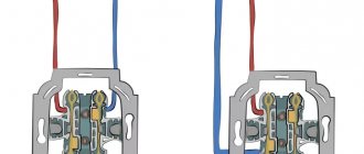
Some measurements are easier and more convenient to make at the location where the devices are installed. For example, checking a socket (socket group) will involve alternately measuring the insulation resistance between the PE terminal and the zero and phase contacts. And then - between zero and phase. Total - three measurements. If the outlet line does not require grounding, then one measurement is required - between L and N.
Next, for greater clarity, we can demonstrate two examples of practical work with a megger.
An example of measuring the insulation resistance of a conventional power cord
So, you need to make sure that the insulation of the power cord is reliable (this can be just a piece of cable or wire.
| Illustration | Brief description of the operation performed |
| This modern electronic megohmmeter UT-505 will be used for work. | |
| The entire set - the megohmmeter itself, measuring leads with probes and clamps, a power adapter, is placed in a convenient case. | |
| The device itself is slightly larger in size than a regular multimeter. But for megohmmeters it is considered very compact. By the way, as you can see, it also has multitester functions - it is possible to measure direct or alternating voltage, measure resistance in the full range of values. To operate in multimeter mode, there is a separate pair of sockets for connecting test leads - it is located on the left. On the right are sockets for operating in megger mode. | |
| The kit includes two high-quality flexible test leads, red and black. If necessary, you can attach an alligator clip to their end... | |
| ...or a probe with a convenient insulated handle. | |
| Device controls. We will not go into detail about all of them - they may differ for different models of megohmmeters. In this case, we are more interested in the operating mode switching handle - when testing insulation, it should be set to the required calibrated voltage value. This model has five such positions - 50, 100, 250, 500 and 1000 volts. This is quite enough to work under normal power grid conditions. In addition, the “basic” values can be slightly changed upward and downward using the “up” and “down” buttons. Well, the large “TEST” button stands out well against the general background. This is what starts the measurement. | |
| The task is to check the quality of the power cord insulation for a possible short circuit. Alligator clips are placed on the measuring wires - in this case it will be more convenient to use them. The ends of the wires are connected to the corresponding right sockets of the device. Then the clamp is installed on one contact pin of the cord plug... | |
| ...and then the second wire is switched in the same way - to the second pin of the plug. | |
| The operating mode switch of the device is moved to the test voltage position of 1000 volts. | |
| If desired or necessary, you can slightly increase or decrease the calibrated voltage using the up and down arrow buttons. So, the operator considered it necessary in this example to increase the voltage to 1200 volts. Its value is shown on the display. | |
| When ready for measurement, all that remains is to press the start button - “TEST”. | |
| After a few seconds, the measured insulation resistance value appears on the display. More precisely, in this example and on this device it is shown that the resistance was more than 20 gigaohms (˃ 20.0 GΩ). This is many times higher than the permissible minimum, that is, there is no need to fear a short circuit on a tested pair of wires. In a similar way, you can immediately test these wires one by one with the protective grounding conductor, that is, take two more measurements. Then there will be firm confidence that the cord is completely safe and suitable for further use. The example with the cord is taken to simplify perception. But hidden home wiring lines are also tested for short circuits in the same way. |
An example of measuring the insulation resistance of the windings of a three-phase asynchronous motor
One of the common reasons for the failure of such motors is breakdown of the windings through the insulation to the housing. Which, by the way, can pose a considerable danger to people. Therefore, such power drives are also regularly tested for insulation quality. An example is shown in the table below. And the ESO202/2-G megger model, which has already become a kind of “classic”, will be used, which is still in production and is in demand.
| Illustration | Brief description of the operations performed |
| This engine needs to be checked. The megohmmeter is getting ready for work - it is removed from the case. | |
| Instrument scale. More precisely, there are two scales. The first, located at the bottom, allows you to measure resistance from zero to 50 MOhm. (If we are closer to reality, then the zone of accurate measurements still starts from approximately 500 kOhm) and higher. The first scale is counted from right to left. The second, upper scale is graduated from left to right, and data on it is read in the range from 50 MOhm to 10 GOhm. | |
| There are two switches on the front panel of the device. The left one sets the scale on which readings will be taken, depending on the expected values. When checking the insulation resistance, it is better to start measurements immediately from the second scale, and only if the obtained value is less than the lower limit of the range (50 MOhm) do they move to the first. The right switch is responsible for setting the value of the calibrated test voltage. In this model, as you can see, there are three positions - 500, 1000 and 2500 volts. | |
| Sockets for connecting test leads. Their “pinout” has already been discussed above. | |
| Wires are connected. Single - to the “Z” (or minus) socket, the second, with a double end - to the “L (+)” and “E” sockets in accordance with the indicators on the plugs. | |
| On the electric motor, remove the cover of the switching box. Screw terminals for connecting three phases are visible. | |
| The alligator clip of the wire coming from the megohmmeter connector “Z” is attached to the motor housing. You can install it on the appropriate terminal, or directly on the metal case, if the absence of paint or other contamination guarantees reliable contact. | |
| The switches are set to the desired position - to the second scale and to a voltage of 500 volts (although, of course, it would be more reliable to check at a level of 1000 volts). | |
| The probe or alligator clip of the second control wire is installed on the terminal of one of the windings. The sequence of checking the phases does not matter. If a probe is used, then it is better to carry out the work with an assistant, since holding contact and rotating the inductor handle alone is inconvenient and unsafe. | |
| Begin to rotate the handle of the voltage generator. Rotation frequency – at least 2 revolutions per second. The arrow on the instrument scale begins to change its position. At a certain moment, the “VN” - “High Voltage” signal light comes on. This means that the required calibrated voltage level has been reached. | |
| But the rotation does not stop until the position of the arrow stabilizes - and only then the readings are taken. In this example, it “went off scale” beyond the maximum value. That is, the insulation resistance of the tested winding is above 10 GOhm. Excellent result! The probes are discharged by mutually touching one to the other. And then, in the same way, the second and third windings are checked sequentially relative to the housing. If everything is fine, then you don’t have to worry about their isolation. | |
| Even such a megohmmeter, which does not have a multitester function, allows you to immediately check the integrity of the “star”. That is, the conductivity of the windings among themselves. To do this, the left switch is switched to the first, lower scale. | |
| The blue wire “crocodile” is installed on one of the phase terminals of the motor. | |
| The probe of the second wire is on one of the remaining terminals. | |
| Rotate the dynamo handle and observe the instrument readings. The lower scale is activated, that is, a resistance of less than 0 MOhm is displayed. The specific value in this case is not important - it is quite obvious that there is conductivity between these two windings, there is no break in them. What needed to be proven! | |
| Then the second pair of windings is tested in the same way... | |
| ...and finally the third. All possible options have been checked, and if the results are positive, then the engine “star” is in perfect order. And the result of both stages of testing is a logical conclusion - in terms of electrical engineering, the engine is completely suitable for operation. |
* * * * * * *
Of course, it is difficult to show all the options for using a megger. And given the modern variety of models, it’s completely impossible. This means that you will have to follow the instructions supplied with the device. But the principles of measurement and safety requirements do not differ significantly.
At the end of the publication, to expand the information somewhat, there is a short video review of the MS5203 MASTECH megger.
Video: How to use the electronic megger MS5203 MASTECH
OCCUPATIONAL SAFETY REQUIREMENTS BEFORE STARTING WORK
2.1. Before starting work with a megohmmeter, it is necessary to find out what category of danger the room in which the work is to be performed belongs to. 2.2. Before starting work with the megohmmeter, you should externally check the serviceability of the housing parts and check its operation. 2.3. A megohmmeter that has defects or is overdue for periodic verification is not allowed to be used. 2.4. To monitor serviceability, the megohmmeter must undergo periodic state verification. 2.5. The employee must personally ensure that all measures necessary to ensure safety are completed. 2.6. An employee should not start work if he has doubts about ensuring safety when performing the upcoming work. 2.7. Before starting work, you need to make sure there is sufficient lighting in the workplace. 2.8. Before starting work, you should pay attention to the rational organization of the workplace.
Device and principle of operation
Using a megohmmeter, the insulation resistance is measured. The measurements refer to work with increased voltage. This device comes in two types - digital and electromechanical.
Download documents from the article:
An electromechanical megohmmeter is a reliable measurement tool, but its accuracy is lower compared to a digital one, although the performance characteristics and service life are much better. The data scale of an electromechanical device consists of three marked parts, the highest of which is the high voltage region. The electrician selects the type of measurement voltage with a toggle switch - from 250 to 2500 Volts in some models. The instrument readings are displayed on the scale using an arrow.
Digital megohmmeters replaced analog ones relatively recently and have proven themselves to be more accurate with more accurate readings and ease of operation. This device is lighter in weight, but this is where its advantages are exhausted.
Digital electrical measuring instruments are complex electronic devices that are prone to frequent breakdowns and depend on various climatic factors and operating conditions, unlike analog ones. Repairing a digital megohmmeter is sometimes equal to the cost of a new device.
All devices must be verified and calibrated at accredited Rosstandart metrology testing centers and have an operational passport.
OCCUPATIONAL SAFETY REQUIREMENTS DURING WORK
3.1. Measurements with a megohmmeter during operation are permitted to be carried out by trained electrical personnel. 3.2. In electrical installations with voltages above 1000 V, measurements should be made according to orders, in electrical installations with voltages up to 1000 V - by order. 3.3. In cases where measurements with a megohmmeter are included in the scope of work, it is not necessary to stipulate these measurements in the work order or order. 3.4. An employee with group III can measure insulation resistance with a megohmmeter. 3.5. Measuring the insulation resistance with a megohmmeter should be carried out on disconnected live parts from which the charge has been removed by first grounding them. 3.6. Grounding from live parts should be removed only after connecting the megohmmeter. 3.7. When measuring the insulation resistance of live parts with a megohmmeter, the connecting wires should be connected to them using insulating holders (rods). 3.8. In electrical installations with voltages above 1000 V, in addition, dielectric gloves should be used. 3.9. When working with a megohmmeter, touching the live parts to which it is connected is not allowed. 3.10. After completion of work, the residual charge should be removed from live parts by briefly grounding them. 3.11. It is prohibited to operate a megohmmeter from ladders; To perform work at height, use durable stepladders or scaffolds. 3.12. It is prohibited to operate a megohmmeter that is not protected from drops and splashes under conditions of their exposure, as well as in open areas during rain or snowfall. 3.13. A megohmmeter connected to live parts should not be left unattended, nor should it be handed over to persons not authorized to work with it. 3.14. When moving a megohmmeter from one workplace to another, as well as during a break in work and its termination, the megohmmeter must be disconnected from live parts.
What safety measures should be observed when working with a megger?
Everything seems to be extremely simple. But it turns out that such devices belong exclusively to the professional category. And not all workers can be allowed to operate them - certain training and obtaining the appropriate permit are required - not lower than the third electrical safety group.
In this case, the author of the article in no way recommends, as is usually customary on construction sites, to take measurements with your own hands. But if any owner of a house or apartment takes upon himself the courage and responsibility for performing independent measurements, he must at least comply with the safety requirements for performing work as much as possible.
- The device itself should not have any mechanical damage to the housing. Particular attention is paid to the integrity of the insulation of the measuring leads, the serviceability of the probes, alligator clips, and pin contacts for connecting to the megger.
- Any tested object or line must be de-energized. All circuit breakers are switched to the “off” position or, in old switchboards, the fuses - plugs - are unscrewed. In some cases, it is necessary to temporarily disconnect the wires from the output terminals of the circuit breakers.
Before testing the insulation resistance, the facility is completely de-energized.
It is advisable to emphasize the deliberately disconnected state of the network by installing a sign, for example, “Do not turn on! Work is underway." So that none of the household or assistants accidentally turn on the machines during testing.
- All devices are disconnected from the network. The plugs are removed from the sockets. Light bulbs are unscrewed from lamp sockets. Particular attention is paid to devices with precision electronics. The high voltage supplied to the line can easily “kill” them.
Plugs are pulled out of all sockets. The lamps are unscrewed (removed) from the lamps (don’t forget about spotlights).
- The so-called portable grounding is being prepared for work. Craftsmen use a factory-made device, but it is quite possible to make a completely working device yourself.
Factory-produced portable grounding.
Something similar can be done with your own hands. It can be a piece of copper stranded wire of the required length, with a cross-section of at least 1.5 mm². One end of it is stripped and can be equipped with a terminal or alligator clip for connection to a grounding bus. The second end, also stripped, must be secured to a dielectric rod. It’s good if you can find a plastic rod of the required length. If not, then a dry wooden strip will do, on the edge of which the stripped end of the wire is attached, for example, with several turns of electrical tape. The place on the bar that you have to grasp with your hands can also be “dressed” in a couple of layers of electrical tape. And the length of the rod is chosen such that it is convenient to touch the ends of the tested wires from a safe distance.
After each measurement, it is recommended to remove the residual voltage in the conductors being tested by touching this portable ground. By the way, when testing lines of considerable length, a serious charge may remain in them, capable of causing severe electrical injury.
- It is advisable to carry out work on measuring insulation resistance while wearing dielectric gloves. Many people ignore this, and probably in vain. During measurements, especially due to inexperience, it is okay to touch the probe or live part, say, with the back of your hand. And you have to work with voltages that sometimes reach 2500 volts! Not a joke!
- The probes must be handled correctly. If you pay attention, each of them has a side on the handle, a kind of guard. This is not so much for convenience as for safety. This sets the boundary of the finger-safe zone, which is prohibited from crossing when taking measurements.
Guards on the probe handles clearly limit the position of the operator's fingers. Closer to the exposed part it becomes dangerous.
- After each measurement, the residual voltage in the megger probes must also be removed. To do this, their bare ends are simply closed together. It must be said that modern devices are often equipped with an automatic discharge function after each reading is taken. But it’s better to be on the safe side, and for many electricians, this type of contact closure after each measurement has simply become a habit.
OCCUPATIONAL SAFETY REQUIREMENTS IN EMERGENCIES
4.1. If during operation any malfunction of the megohmmeter is discovered, work with it must be stopped immediately, and the faulty megohmmeter must be handed over for inspection and repair. 4.2. If there is a sudden loss of voltage in the network, the megohmmeter must be disconnected from live parts. 4.3. In the event of an accident, you must immediately provide first aid to the victim, call a doctor by calling 103 or 112 or help take the victim to a doctor, and then inform the manager about the incident. 4.4. If an injury occurs due to exposure to electric current, then first aid measures depend on the state in which the victim is after he is released from the action of electric current: 4.4.1. If the victim is conscious, but has previously fainted, he should be placed in a comfortable position and ensure complete rest until the doctor arrives, continuously monitoring his breathing and pulse; Under no circumstances should the victim be allowed to move. 4.4.2. If the victim is unconscious, but with stable breathing and a pulse, he should be placed comfortably, his clothes unbuttoned, a flow of fresh air created, ammonia sniffed, sprinkled with water and complete rest ensured. 4.4.3. If the victim is breathing poorly (very rarely and convulsively), he should undergo artificial respiration and cardiac massage; if the victim has no signs of life (breathing and pulse), he cannot be considered dead, artificial respiration should be performed continuously both before and after the arrival of the doctor; The question of the futility of further artificial respiration is decided by the doctor. 4.5. If a fire or signs of combustion are detected (smoke, burning smell, increased temperature, etc.), you must immediately notify the fire department by calling 101 or 112. 4.6. Before the fire department arrives, measures must be taken to evacuate people and property and begin extinguishing the fire.
User manual
The insulation resistance is checked on de-energized equipment or cable lines or electrical wiring. Remember that the device generates high voltage and if the safety precautions for using a megohmmeter are violated, electrical injuries are possible, because Measuring the insulation of a capacitor or long cable line can cause a dangerous charge to accumulate. Therefore, the test is carried out by a team of two people who have an understanding of the dangers of electric current and have received safety clearance. During testing of the object, no unauthorized persons should be nearby. Remember about high voltage.
Each time the device is used, it is inspected for integrity, for the absence of chips and damaged insulation on the measuring probes. Trial testing is carried out by testing with open and closed probes. If tests are carried out with a mechanical device, then it must be placed on a horizontal, flat surface so that there is no error in the measurements. When measuring insulation resistance with an old-style megohmmeter, you need to rotate the generator handle at a constant frequency, approximately 120-140 rpm.
If you measure resistance relative to the body or ground, two probes are used. When testing the cable cores relative to each other, you need to use the “E” terminal of the megohmmeter and the cable screen to compensate for leakage currents.
Insulation resistance does not have a constant value and largely depends on external factors, so it can vary during measurement. The check is carried out for at least 60 seconds, starting from 15 seconds the readings are recorded.
For household networks, tests are carried out with a voltage of 500 volts. Industrial networks and devices are tested with voltages in the range of 1000-2000 volts. You need to find out exactly what measurement limit to use in the operating instructions. The minimum permissible resistance value for networks up to 1000 volts is 0.5 MOhm. For industrial devices, no less than 1 MOhm.
As for the measurement technology itself, you need to use a megohmmeter according to the method described below. As an example, we took the situation with measuring insulation in a switchboard (power panel). So, the procedure is as follows:
- We remove people from the part of the electrical installation being tested. We warn about the danger and post warning posters.
- We remove the voltage, completely de-energize the shield and input cable, and take measures against erroneous voltage supply. We hang up a poster - DO NOT TURN ON, PEOPLE ARE WORKING.
- We check that there is no voltage. Having previously grounded the terminals of the test object, we install the measuring probes, as shown in the megohmmeter connection diagram, and also remove the grounding. This procedure is carried out with each new measurement, since nearby elements can accumulate a charge, introduce an error in the readings and pose a danger to life. Installation and removal of probes is carried out using insulated handles while wearing rubber gloves. Please note that the insulating layer of the cable must be cleaned of dust and dirt before checking the resistance.
- We check the insulation of the input cable between phases A-B, B-C, C-A, A-PEN, B-PEN, C-PEN. The results are recorded in the measurement protocol.
- We turn off all automatic devices, RCDs, turn off lamps and lighting fixtures, disconnect the neutral wires from the neutral terminal.
- We measure each line between phase and N, phase and PE, N and PE. The results are entered into the measurement protocol.
- If a defect is detected, we disassemble the measured part into its component elements, look for the fault and fix it.
At the end of the test, we use portable grounding to remove the residual charge from the object, by short-circuiting, and from the measuring device itself, discharging the probes among themselves. According to these instructions, you need to use a megohmmeter when measuring the insulation resistance of cable and other lines. To make the information more clear to you, below we have provided videos that clearly demonstrate the order of measurements when working with certain models of devices.
OCCUPATIONAL SAFETY REQUIREMENTS AFTER WORK COMPLETION
5.1. After finishing work, turn off all measuring equipment. 5.2. At the end of the work, it is necessary to clean the megohmmeter and the personal protective equipment used from dirt, dust and put it in order. 5.3. Any malfunctions and malfunctions of the tools and equipment used during work, as well as other violations of labor safety requirements, should be reported to your immediate supervisor. 5.4. When finished, wash your hands thoroughly with warm water and soap.
Types of megohmmeters
Today there are two types of megohmmeters on the market: analog and digital:
- Analog (pointer megohmmeter). The main feature of the device is the built-in generator (dynamo), launched by rotating the handle. Analog instruments are equipped with a scale with an arrow. Insulation resistance is measured through magnetoelectric action. The pointer is attached to an axis with a frame coil, which is influenced by the field of a permanent magnet. When current moves through the frame coil, the needle deviates by an angle, the magnitude of which depends on the force and voltage. This type of measurement is possible thanks to the laws of electromagnetic induction. The advantages of analog devices include their simplicity and reliability, the disadvantages are their heavy weight and significant size.
- Digital (electronic megohmmeter). The most common type of meters. Equipped with a powerful pulse generator operating using field-effect transistors. Such devices convert alternating current into direct current; the current source can be a battery or a network. The measurements themselves are carried out by comparing the voltage drop in the circuit with the resistance of the standard using an amplifier. The measurement results are displayed on the device screen. Modern models provide a function for storing results in memory for further comparison of data. Unlike an analog megohmmeter, an electronic one has compact dimensions and light weight.