What is Arduino?
Arduino is a special tool that allows you to design electronic devices that have closer interaction with the physical environment in comparison with the same PCs, which actually do not go beyond virtual reality.
The platform is based on open source code, and the device itself is built on a printed circuit board with software embedded in it.
In other words, Arduino is a small device that provides control of various sensors, lighting systems, data reception and transmission.
Arduino includes a microcontroller, which is a microprocessor assembled on one circuit. Its specialty is its ability to perform simple tasks. Depending on the model, the Arduino device can be equipped with various types of microcontrollers.
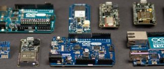
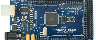
There are several models of boards, the most common of them are UNO, Mega 2560 R3.
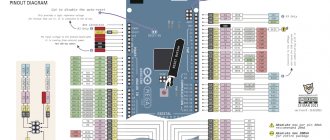
An equally important feature of the printed circuit board is the presence of 22 pins, which are located around the perimeter of the product. They are analog and digital.
The peculiarity of the latter is that it is controlled using only two parameters - a logical one or zero. As for the analog pin, there are many small regions between 1 and 0.
Today, Arduino is used to create electronic systems that can receive information from various sensors (digital and analog).
Arduino devices can work in conjunction with software on a computer or independently.
As for the boards, you can assemble them yourself or purchase a finished product. Arduino programming is done in the Wiring language.
READ ON THE TOPIC: Xiaomi Smart Home, review, equipment, connection and setup with your own hands, scenarios.
System stuff
Working with memory
- EEPROM is a standard library for working with EEPROM. I recommend using the more convenient EEPROMex
- EEPROMex is a more convenient library for working with EEPROM memory. Description
- EEPROMWearLevel – “manager” of EEPROM memory, monitors the number of cell rewrites
- MemoryFree is a library for studying the current occupancy of SRAM memory. Description
- EEWrap - the library allows you to use EEPROM as random access memory (SRAM), i.e. for storing variables
- Flash - library allows you to conveniently store/read any data in the Flash memory of the microcontroller (arrays, lines with text...)
- PGMWrap is another powerful library for writing/reading data to Flash memory
- optiboot_flash – a modified OptiBoot bootloader, which adds the ability to work with Flash memory during code execution (think of SRAM expansion due to Flash!)
Working with pins
- DirectIO is a faster alternative to standard read/write pin state functions
- AnalogReadFast – fast option for reading an analog pin (21 µs)
- CyberLib is a cool collection of fast analogues of Arduino functions, read the description. Note: the author of this open source library does not like it being used in his projects, so be careful.
- GyverHacks is a collection of quick analogues of Arduino functions, not as fast as CyberLib, but more familiar to use. Changing PWM frequency/bit size
- SoftPWM – we make software PWM on different pins
- PWM – a library that allows you to set the PWM frequency
- GyverPWM – powerful library for advanced PWM generation (ATmega328 only)
- PinChangeInt – we make interruptions on any pin. How so? There is a description
- PinChangeInterrupt - another library (better) that allows you to catch interrupts on any pin
- analogComp – work with a microcontroller analog comparator
Deep Settings
- GyverHacks – in addition to what is described above, there are some in-depth settings, measurement of reference voltage and core temperature (for ATmega328 )
- GyverTimer012 – lightweight library for managing interrupts on all three ATmega328
- directTimers - a library for advanced manual control of timers on the ATmega328 , reveals all the capabilities and settings of timers
- directADC - a library for advanced manual control of the ADC and comparator on the ATmega328 , reveals all the capabilities and settings of the ADC
- GyverPower is the lightest and most universal library for managing sleep, peripherals and system clock
- Low-Power – a powerful library for managing power saving and sleep mode
- narcoleptic – another very easy to use hibernation library
- SoftwareReset – access to reboot Arduino “from a sketch”
- WatchDog is a library for working with a “watchdog” that reboots the MK in case of freezing. Another option
- Adafruit-Trinket-USB – USB emulation library for ATtiny85 (Digispark board). Simulates a keyboard/mouse
- TrinketHidCombo_MEGA328 – USB emulation library for ATmega328 (UNO/Nano/Pro Mini boards). Simulates a keyboard/mouse. There is an example on the forum. Original post on the forum. Download from FTP site. Download from the Mail cloud. Download from Yandex Disk.
- DMBS AVR lib – a set of light and fast basic functions for working with MK without a kernel (analogous to avr libs)
- LUFA – lightweight USB framework for AVR
Kernels and bootloaders
- megaTinyCore is my version of the core for boards with ATmega168/328 on board (UNO, Nano, Mini), based on the original Arduino core, standard functions have been greatly accelerated and simplified. Recommended for heavy and speed-demanding projects.
- optiBoot is a cool bootloader for Arduino, faster, lighter and more functional
- HoodLoader – loader for MK 16u2 with HID support (read: turns the original UNO into a Leonardo analogue with HID support)
- ArduinoXInput_AVR – core for boards based on ATmega32U4 (Leonardo, Micro), which turns the board into a controller with XInput support (Xbox gamepad). To create a game controller you will also need the ArduinoXInput library. There is a guide in English
- GyverCore is a lightweight and fast core for ATmega328 (Arduino NANO), which my colleague and I developed. Lightweight and fast, the ability to work without a bootloader and a wide selection of clocking options and general system settings.
- MiniCore is a core for supporting ATmega328, ATmega168, ATmega88, ATmega48 and ATmega8 microcontrollers, based on optiBoot. One of the main features is support for an internal clock generator!
- MicroCore – core to support ATtiny13, ATtiny13A and ATtiny13V microcontrollers with selectable internal clock frequency
- ATTinyCore – core for supporting ATtiny 441/841, 44/84, 45/85, 461/861, 48/88, 828, 1634, 87, 167 microcontrollers, again based on the cool OptiBoot.
- megaTinyCore – core for supporting ATtiny 3217, 1617, 817, 417, 3216, 1616, 816, 416, 1614, 814, 414, 214, 412, 212, 1607, 807, 1606, 806, 406, 160 microcontrollers 4, 804, 404 , 204, 402, 202. New models are sewn using UPDI; read an excellent article on this topic in Russian.
- nanoBoot – lightweight (512 byte) bootloader for ATmega32xx4 with HID support
Task and Thread Managers
- ArduinoThread - a library for creating “threads” - separately executed tasks using a timer or something else
- EventManager – a library for working with events (again, a timer-in-your-code)
- Arduino-fsm is another task manager that allows you to write clear, understandable code with a bunch of tasks running on a timer
- Automaton is another framework for writing sketches with tasks and timers. There is a wiki
- FreeRTOS is a real-time operating system for Arduino. Tasks, threads...
- Arduino_FreeRTOS - another version of RTOS
- GyverRTOS - my simple RTOS with sleep mode (based on the Low-Power library)
- DeepSleepScheduler – task manager with built-in sleep mode
What does Arduino control?
Thanks to the large number of pins on the printed circuit board, it is possible to connect many different devices to Arduino, namely:
In addition, a set of sensors is connected to Arduino depending on the tasks assigned to the system. As a rule, sensors for light, smoke and air composition, magnetic field, humidity, temperature and others are installed.
Thanks to this feature, Arduino becomes a universal device - “a brain device with the ability to be configured taking into account the tasks at hand.
How the system works
The Arduino device works as follows. Information collected from various sensors in the home is sent wirelessly to a tablet or PC. Next, using special software, the data is processed and a specific command is executed.
The main function is performed by a central sensor, which you can purchase or assemble yourself. The connectors on the boards are standard, which greatly simplifies the selection of components.
Nutrition
The Arduino is powered via a USB connector or from an external power supply. The voltage source is determined automatically.
If you select the option with external power supply not via USB, you can connect a battery or power supply (voltage converter). In the latter case, the connection is made using a 2.1 mm connector with a “+” on the main contact.
The wires from the battery are connected to various terminals of the power connector - Vin and Gnd.
For normal operation, the platform requires a voltage of 6 to 20 Volts. If the parameter drops below 7 volts, the 5V pin may have less voltage and risk a failure.
If you supply 12 V, the voltage regulator may overheat and damage the board. For this reason, the optimal level is power supply using 7 - 12 V.
Unlike previous types of boards, the Arduino Mega 2560 works without the use of a USB FTDI microcontroller. To ensure information exchange via USB, a USB-to-serial converter programmed for the converter is used.
POPULAR WITH READERS: What is a CLAP smart home.
The Arduino has the following power pins:
- 5V - used to supply voltage to the microcontroller, as well as other elements of the printed circuit board. The power supply is adjustable. Voltage is supplied via a USB connector or from the VIN pin, as well as from another 5 Volt power source with the ability to regulate.
- VIN - used to supply voltage from an external source. The output is necessary when it is not possible to supply voltage via a USB connector or other external source. When voltage is applied to the 2.1mm jack, this input is used.
- 3V3 is a pin whose voltage is a consequence of the operation of the FTDI chip itself. The maximum current consumption level for this element is 50 mA.
- GND - grounding terminals.
The circuit diagram of the board in pdf format can be viewed HERE.
Connection
Arduino capabilities allow you to connect a group of devices that provide stable communication with a PC, as well as other system elements - microcontrollers or the same Arduino boards.
The ATmega 2560 model is distinguished by the presence of 4 ports through which data can be transferred for TTL and UART. A special ATmega 8U2 chip on the board transmits the interface (one of them) via a USB connector. In turn, programs on the PC receive virtual COM.
There are nuances here that depend on the type of operating system:
- If Linux is installed on the PC, recognition occurs automatically.
- If you are using Windows, you will need an additional .inf file.
Using the monitoring utility, you can send and receive information in text format after connecting to the system.
Flashing TX and RX LEDs indicate data transmission. A special Software Serial library is used to send information sequentially.
Features of the ATmega 2560 include the presence of SPI and I2C interfaces. In addition, Arduino includes the Wire library.
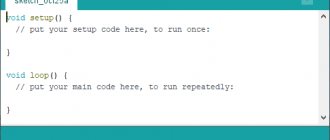
Examples of sketches
You can consider some examples of sketches that will become a guide for the subsequent operation of the equipment. I will try to implement each of the examples in the following materials. Today we’ll just talk about possibilities.
Example 1
One of the interesting sketches can be used to display the actual operating time of the controller, followed by the adoption of the “blink” command, which is intended to initialize the blinking procedure of LED elements.
In fact, there is nothing particularly useful in the sketch, but it also includes the possibility of randomly outputting a certain phrase “ Data Received ”; it can be used in the future directly for testing and analyzing the established rules for the operation of a modular element.
Example 2
Connecting a special sensor of the current water level, a rain sensor. To implement a specific project, you must have:
- the water sensor itself,
- Arduino controller,
- set of connecting wires,
- computer with cables and IDE program corresponding to the development board.
As a result, thanks to the relatively simple setup of the microcontroller, optimal conditions for the operation of the sensor are created - see the project in our lessons.
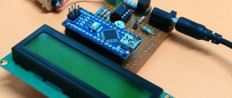
Example 3
Special attention should be paid to the ability to output characters and then install fonts on the LCD5110 , which will ensure the easiest and most reliable control over the state of the equipment itself.
Fonts are output and changed using Arduino capabilities. In this case, you will need to use a ready-made data library, as well as source code.
Project development
There are many Arduino devices on the market today, with different configurations. But there is no universal solution “for all occasions”. Depending on the task at hand, each kit is selected individually. To avoid mistakes, project development is required.
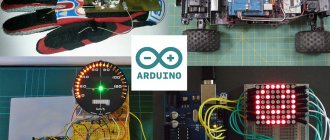
What projects can be created on Arduino?
Arduino allows you to create many unique projects. Here are just a few of them:
- Solving a Rubik's cube (the system solves it in 0.887 s);
- Controlling humidity in the basement;
- Creation of unique paintings;
- Sending messages;
- Balancing robot on two wheels;
- Sound spectrum analyzer;
- Origami lamp with capacitive sensor;
- Robotic arm controlled by Arduino;
- Writing letters in the air;
- Flash control and much more.
We select the equipment for the project using the example of Arduino Mega 2560 R3
To create a full-fledged Smart Home system and perform its assigned functions, it is important to correctly approach the configuration and selection of equipment.
What's included in the package?
If your goal is a “Smart Home” based on Arduino, you need to prepare the following equipment - the Mega 2560 R3 board itself, an Ethernet module (ENC28J60), a motion sensor, as well as other sensors and controllers.
In addition, it is worth preparing a twisted pair cable, a resistor, a relay, a switch and a cable for the Ethernet module.
Additional tools are also needed - screwdrivers, soldering irons, etc.
Please note that you should buy kits for installing the system at certified points. This is due to the fact that the project uses electricity, and the use of counterfeits can lead to a decrease in safety.
All programs for adaptation can be found online on the official Arduino website https://arduino.ru. When choosing sensors, you should focus on the tasks that the Smart Home must solve.
Typically, motion, temperature, door opening and light sensors are required. The role of a door opening sensor can be performed by a regular reed switch.
The board is flashed using special software designed for various operating systems, including a USB cable. In this case, there is no need for programmers.
As for the software used in Arduino, it is written in C language. There are certain restrictions on the number of bytes, but the current memory is sufficient to implement the task.
Incredible projects with Arduino
The ultimate goal of these manipulations is to provide easy control of numerous external devices. This board interacts with the outside world through many add-ons:
- sensors,
- LEDs,
- engines,
- and so on.
This will make it a fairly universal platform for many projects of very different levels - see the section on our website Arduino Lessons. Currently, there are quite a lot of different microcontrollers, among which Arduino is especially popular, which is associated with the active posting of the most incredible projects and developments on the network.
In order to easily implement one of millions of ideas, you can easily use the most current information that is available independently on many sites. Below is an example of the implementation of one of these ideas - a Christmas bell that can be controlled:
We will look at how to do it in one of the following lessons.
If you don’t have even a little experience working with microcontrollers (programming and configuration), thanks to the features of Arduino, you can easily learn on your own by conducting relatively short experiments. Below I propose to analyze some of the capabilities of Arduino, examples of where it is best to use this unique constructor.
Beginning of work
Once the necessary equipment is prepared and the project is developed, you can begin to complete the task.
Stages
When organizing a Smart Home system based on Arduino, you should follow the following algorithm:
- Installation of program code;
- Application configuration for the device used;
- Port forwarding (for router);
- Carrying out tests;
- Making edits and so on.
The Internet has all the necessary software for the equipment used - just download it from the official website and install it (see link above).
The application allows you to see information about sensors. If required, the IP address settings can be changed.
Sequence of actions when connecting to a computer
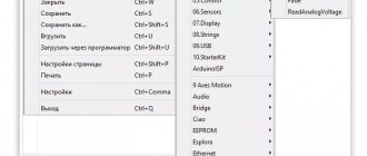
To get started with Arduino on Windows, follow these steps:
- Prepare the necessary equipment - USB cable and Arduino.
- Download the program from arduino.cc/en/Main/Software.
- Connect the board using a USB cable. Make sure the PWR LED lights up.
- Install the necessary set of drivers to work with Arduino. At this stage, you should start the driver installation and wait for the process to complete.
Then click on the “Start” button and go to the control panel. There, open the “System and Security” tab and select the “System” section. After opening the window, select “Device Manager”, click on the Arduino name and use the right mouse button to specify the driver update command. Find the line “Browse my computer for Driver software!”, click on it and select the appropriate driver for your board type - ArduinoUNO.inf (located in the drivers folder). It could be UNO, Mega 2560 or another. - Launch the Arduino development environment by double-clicking on the application icon.
- Open the finished example (File - Examples - 1.Basics - Blink).
- Select a board. To do this, go to the Tools section, and then to the Board Menu.
- Install the serial port (you can find it by unplugging and plugging the cable).
- Download the sketch in Arduino. Click on “Upload” and wait for the TX and RX LEDs on the board to blink. Finally, the system shows that the download was successful. A few seconds after completion of work, LED 13 L should light up (it will flash orange). If so, the system is ready to perform tasks.
Working with a router
For the Smart Home to function properly, it is important to handle the router correctly. Here you need to perform the following steps - open the configuration, specify the Arduino IP address, for example, 192.168.10.101 and open port 80.
Afterwards you need to assign a domain name to the address and proceed to the project testing process. Please note that for such a system it is prohibited to use a public IP address, because in this case there is a high risk of hacking through the Network.
Connecting and flashing Arduino Leonardo
Connecting the device requires a USB cable connected to the PC or power supply from an external source.
Connecting the device requires a USB cable connected to the PC or power supply from an external source. This can be a remote battery or an AC/DC adapter. This solution made the controller cheaper to manufacture and increased the flexibility of use when working with a computer.
When installing the Arduino Leonardo driver, you need to proceed as follows:
- connecting the device to a PC;
- waiting for the software installation wizard to start (if it doesn’t start, manually go to the equipment section, select the Arduino Leonardo line and click update);
- search for drivers on your PC and click “Next”;
- in the software folder, select the required driver;
- agreement with the installation.
To flash the device's firmware, just click the Upload button to automatically load the software into the device's memory. Next, a controller reset is initiated, which leads to the launch of the bootloader (responsible for receiving, saving and starting new software). Unlike other models, here after an automatic reset the platform waits for a new serial port. Next, the sketch is sent to the newly created COM port. If the automatic reset is not activated for any reason, you need to do the following:
- pressing the reset button and holding it until the word Uploading appears;
- bootloader startup control (the system must see the new port).
These steps are necessary if the standard firmware system does not work.
Expanding capabilities on Arduino
One of the capabilities of a smart home is visualization of the state of automation and processes occurring in the system. To do this, it is recommended to use a separate server that provides state processing (the Node.js program can be used).
The mentioned software technology is used to solve Internet problems, therefore, to visualize the “Smart Home”, the Java Script language is used (it is with its help that the processor and server are created). The results can be seen on your computer or PC screen.
To implement your plan, a laptop, a regular PC or a Raspberry Pi will be suitable. The use of such a system allows you to increase its capabilities. So, if the Arduino board has a small amount of memory, there are no such restrictions on the server. The program is written in such a way as to provide full control of the platform.
If desired, you can set an algorithm that will record the fact that a person is in the house and collect this information. If the owner returns around 5:30 pm every day, the boiler or heating devices can be turned on an hour before. Upon arriving home, a person finds himself in a warm building with hot water.
The program can remember the time when the owner goes to rest and turn off the water heating. There are many such nuances that, if necessary, are introduced into the program. It is the presence of an external PC that gives great opportunities to the Arduino controller.
Communication with Arduino
To know what actions to perform, the processor must receive the appropriate command. Communication is carried out using a special language, which is adapted for working with Arduino and is quite simple. If desired, it is easy to work with even without programming skills.
Formatting and sending a message to the controller is called programming. To simplify the process, the Arduino IDE has been developed, which includes many programs. Studying them allows you to get a lot of useful information about working with Arduino.
Some iron
- GyverStepper is a high performance stepper motor control library
- AccelStepper is a more interesting and high-quality replacement for the standard Stepper library for controlling stepper motors. You can download it from the developer’s page, or here is a direct link to the archive.
- AccelMotor - my library for controlling a motor with an encoder (turns a regular motor into a “stepper” or servo motor)
- ServoSmooth is my addition to the standard Servo library, allowing you to control a servo with adjustable maximum speed and acceleration/braking (like AccelStepper, only for servos). A must have for any lover of servo manipulators!
- CapacitiveSensor – a library for creating touch buttons (from a pair of loose components). Description
- ADCTouchSensor is another version of the library for creating touch buttons. There's one more, just in case
- TouchWheel - a library for creating touch sliders and rings
- Buzz is a presence detector based on just one wire! (measures EM waves)
- Bounce is an anti-bounce library for buttons and such. Questionable usefulness, but read the description
- oneButton – library for advanced work with buttons. In my opinion it is inconvenient
- GyverButton is my library for advanced button manipulation. Lots of possibilities!
- AdaEncoder – library for working with encoders
- GyverEncoder – my library for encoders with a lot of possibilities, supports different types of encoders
- RTCLib is a lightweight library that supports most RTC modules
- OV7670 – library for working with the camera on the OV7670
- IRremote – basic library for working with IR remote controls and emitters
- IRLib – a more advanced version for working with IR devices
- IRLremote is the clearest library for IR remote controls, it works through interrupts. 100% remote control testing
- keySweeper - an almost ready-made project for intercepting keystrokes from wireless keyboards
- USB_Host_Shield – allows Arduino to work with gamepads (PS, XBOX) and other USB devices
- Brain – library for working with NeuroSky EEG modules
- TinyGPS - a fast library for working with GPS modules
- GyverRGB is my library for working with RGB LEDs and strips
- FadeLED – library for smooth (PWM) blinking of LEDs with different periods
- CurrentTransformer – measurement of current using a transformer (coil) on a wire. Read: current clamps
- LiquidCrystal-I2C is a library for LCD displays with an I2C controller. Developer – fdebrabander
- LiquidCrystal-I2C is a library for LCD displays with an I2C controller. Developer: johnrickman. The previous one seems to be better
- LiquidTWI2 – fast library for LCD displays on MCP23008 or MCP23017 controllers
- LCD_1602_RUS – Russian font library for LCD displays
- LCD_1602_RUS_ALL – new version of the previous library with support for the Ukrainian language
- u8glib – library for working with monochrome LCD and OLED displays
- ucglib – library for working with color LCD and OLED displays
- Adafruit_SSD1306 - another library for OLED displays
- Adafruit-GFX-Library – add-on for adafruit display libraries, allows you to display graphics
- SSD1306Ascii - a self-sufficient and very lightweight library for text output to OLEDs
- NeoPixelBus is a library for working with addressable LED strip, adapted for esp8266 (NodeMCU, Wemos, etc.).
- microLED - a lightweight and simple library for working with address tape
- Gyver433 – a lightweight library for sending any data via 433 MHz radio modules
- rc-switch – a library for working with 433 MHz radio modules and various communication protocols
How can you manage?
As noted, the Node.js server allows you to connect equipment in your home. One of the ways to manage processes is cloud services on the Internet. In this case, you can turn on the heating or boiler one to two hours before arrival.
Another way is to control using messages (MMS or SMS). This option is relevant when there is no connection to the Internet. One of the advantages of the system is the ability to obtain information about a force majeure situation (for example, a leak). The Edison board from Intel helps here.