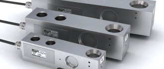
Pressure and weight strain gauges are those devices from the field of weighing technology that are capable of converting the mechanical deformation of objects and bodies into a conventional electrical signal, which subsequently makes it possible to determine the level of compression/extension of a certain body. Such a sensor itself is a resistive converter and is positioned as one of the main components of high-precision weighing equipment. These devices are used in any electronic type scales: from household floor scales to ultra-precise laboratory scales.
The principle of operation of the strain gauge is as follows: when an object is placed on the scale, under its influence (weight) the resistor on which the strain gauge is installed changes (deforms). In turn, the sensor measures the force and amount of deformation of the resistor and transmits data about this to the control board. Thus, the weight of the object on the loading platform is calculated. Weighing equipment can use one or more sensors.
Correctly, such sensors in the engineering environment are called weight meters for scales, and in common parlance they are called “beams”.
What is strain gauge and why are strain gauges needed?
Strain measurement (from the Latin tensus - tense) is a method and technique for measuring the stress-strain state of the measured object or structure. The fact is that it is impossible to directly measure mechanical stress, so the task is to measure the deformation of an object and calculate the stress using special techniques that take into account the physical properties of the material.
The operation of strain gauges is based on the tensoelectric effect - this is the property of solid materials to change their resistance under various deformations. Strain gauges are devices that measure the elastic deformation of a solid and convert its value into an electrical signal. This process occurs when the resistance of the sensor conductor changes when it is stretched and compressed. They are the main element in instruments for measuring the deformation of solid bodies (for example, machine parts, structures, buildings).
Characteristics of strain gauges
Base - length of the grid conductor (0.2-150 mm). Nominal resistance R - the value of active resistance (10-1000 Ohms). The operating supply current Ip is the current at which the strain gauge does not noticeably heat up. When overheated, the properties of the materials of the sensitive element, base and adhesive layer change, distorting the readings. Strain sensitivity coefficient: s =(∆R/R)/(∆L/L), where R and L are the electrical resistance and length of the unloaded sensor, respectively; ∆R and ∆L - change in resistance and deformation due to external force. For different materials, it can be positive (R increases with tension) and negative (R increases with compression). The value of s for different metals varies from -12.6 to +6.
Design
As an example, let's consider the simplest version of a strain gauge, where a strain gauge acts as a sensitive element. Structurally, it can be represented in the form of a thin elastic wire or film distributed over the controlled surface.
The operation of a strain gauge is based on Hooke's law, which states that the change in electrical resistance relative to the initial position of the element is proportional to the elongation or compression of the sensor. Guided by this principle, the proportionality coefficient is determined:
K = Δl / l = ΔR / R
Where:
- K – proportionality coefficient;
- Δl is the magnitude of the change in length during deformation;
- l – length of the measured element at rest;
- ΔR – change in resistance value during deformation;
- R – resistance value of the strain gauge in the normal position.
In practice, this is implemented as follows (Figure 1):
Rice. 1. Strain gauge device
When at rest, the strain gauge tracks have a certain cross-section and conductor length. The resistance of the entire resistive element of the strain gauge will be determined by the formula:
R = (ρ*l)/S, where
- ρ is the resistivity of the material; as a rule, constantan is used as a metal with constant resistivity;
- l – length of the strain gauge conductor;
- S – cross-section of the strain gauge conductor.
Thus, if the strain gauge is extended, the length of the conductive paths increases and the cross-section decreases. As a result, the ohmic resistance of the strain gauge will increase. When compressed, the reverse process will occur - the length of the conductive elements will decrease, and their cross-section will increase. As a result of compression, the resistance of the strain gauge will decrease, which is the basis of its operating principle.
Design and principle of operation
The basis of the strain gauge is a strain gauge equipped with special contacts attached to the front of the measuring panel. During the measurement process, the sensitive contacts of the panel come into contact with the object. Their deformation occurs, which is measured and converted into an electrical signal transmitted to the processing elements and display of the measured value of the strain gauge sensor.
Depending on the scope of functional use, sensors differ in both types and types of measured quantities. An important factor is the required measurement accuracy. For example, a load cell on a truck scale at the exit of a bakery is completely unsuitable for electronic pharmacy scales, where every hundredth of a gram is important.
Tactile
They are triggered by mechanical action on a sensitive surface. They allow you to set minimal deformations, but with inaccurate settings they can give a false signal.
Mechanical
The measurements are based on recording the change in the length of an object under load. The work of a mechanical strain gauge is to determine the dependence of the elongation of a body on the stress in the cross section.
Resistive
The most common type of sensors. They require connection to a low-current control circuit, since they include a strain gauge circuit. Reliable in any environmental condition.
Strings
The string version is a steel wire (string), it is pulled between supports, which are fixed to the surface of the object. The essence of the measurements is to determine the ratio of the vibration frequency of the string to the degree of its tension when the length of the examined body changes under the influence of a load.
Inductive
The device is based on the use of an inductance coil in which a movable core is installed. It is in direct contact with the surface of the object. At the slightest deformation of the surface, the core in the coil shifts. The changing parameters of the inductor are recorded through the electrical circuit by the device.
Piezoresonant
They are semiconductor-type devices and require reliable maintenance and fine tuning. They work on the principle of comparing the reference signal with the actual one.
Piezoelectric
In their action they are similar to meters of the previous type, but they give a signal when the values of contact deformations applied to the sensing element change.
Magnetic
Made from alloys with a variable coercivity value, they are used to measure forces in equipment units operating in strong electromagnetic fields.
Capacitive
Designed to measure small mechanical stresses in parts with a complex configuration, when changing the length of the conductive wire changes its electrical capacitance.
Kinds
The applicability of the measuring elements under consideration is determined by the material from which the sensor is made. Most often, the starting material is constantan alloy, consisting of 40% nickel and 60% copper. For constantan k ≈ 2; other alloys of constant electrical resistance also have the same order of values (1.5...3.5).
Semiconductor type sensors have higher proportionality coefficients. Depending on the semiconductor material (silicon or germanium), as well as the composition of alloying additives, the coefficient values reach 50...70. In this regard, semiconductor strain gauges are more sensitive and are used to evaluate small elongations. At the same time, semiconductor sensors are characterized by increased deviations in their elongation in the ranges of 1.5...9% relative elongation. For wire sensors this figure does not exceed 0.5%.
Wire-type strain gauge designs are developed taking into account the following limitations:
- In order to obtain sufficient measurement accuracy, the resistance value of the wire element must be within 100...1000 Ohms;
- It is advisable to have the wire diameter in the range of 0.01...0.03 mm;
- The length of the wire element should not exceed 250...300 mm.
In some cases, the above restrictions do not allow the installation of strain gauges in the form of wires, so the measuring devices are made of foil or flat measuring grids. To protect against damage that may occur during transportation or assembly of such sensors, a backing made of paper or thin plastic is used to mount them in a floor-mounted version.
To provide electrical contact with the measuring grid, lead wires are placed on the substrate, which are then connected to the sensor by soldering.
Types of strain gauges, including an active measuring element, contact leads and substrate:
- Flat wire.
- Foil.
- Semiconductor, with one or two rods.
- Tubular.
A brief description of the most common designs of strain gauges is given below.
- Console. Designed to measure torque and bending moments, they are installed in the areas of greatest deflection of structures.
- Cylindrical. The least compact, but they make it possible to determine significant stresses, approaching in their values the yield strength of the limiting material.
- S-shaped. They make it possible to evaluate three-dimensional deformations in a volumetric stress-strain state. More often than others they need verification.
Design features
Strain gauges are distinguished by the type of structure, which depends on the type of sensing element. Control of deformation processes is possible using different types of contacts: foil, film or wire.
Indicators with a foil element are used as adhesive strain gauges. Film ones are analogues of foil ones. The difference lies in the material of manufacture. For their production, strain-sensitive films with sputtering are used, which increases the sensitivity of the system.
You need to buy a wire-type strain gauge when you need to measure the load in a wide range: from hundredths of grams to several tons.
Classification of strain gauge equipment
All strain gauge equipment can be divided into classes that characterize the complexity and level of nesting of the technical device:
| Strain gauge. It is the basic unit of strain gauge equipment. It is on the basis of its measurements that the entire subsequent cycle of work is built. At the same time, the strain gauge itself in most cases is not a full-fledged measuring device and in order for it to start working, a strain gauge is required. | |
| Load cell. This is the primary measuring device. It is a strain gauge in a special housing that changes its shape in accordance with the requirements for its operation. The body is made of special steel, which ensures sufficient springiness, return of the strain gauge to its original position and linearity of readings. The quality of the strain gauge housing is one of the most important criteria for the performance of strain gauge equipment. Suffice it to say that it is the composition and grade of steel of the housing that is kept secret by all manufacturers of strain gauges, and not its design. | |
| Terminal. A secondary metering device that converts the output signal from strain gauges into a measurement result and displays it on a digital display. The terminal can operate within a limited range of accuracy, like strain gauges, so it is necessary to select a model that will correctly interpret the readings of the measuring device. Digital terminals are generally tied to several types of sensors via a data transfer protocol and cannot be used in other measuring systems. As well as vice versa. | |
| Measuring device. This is a complex of industrial equipment, consisting of strain gauges, a load receiving platform and a terminal, installed on a specific object - scales, dispenser, dynamometer, machine, press. At the same time, the measuring device is the only type of measuring equipment that is certified for measuring the mass of cargo. A group of strain gauges cannot be called a scale if it has not been verified and calibrated, even if the sensors and terminal are certified. | |
| Periphery equipment. This includes remote displays, video cameras recording weighing results, and software. They expand the capabilities of strain gauge equipment, but are not directly involved in the measurement process. |
It will be interesting➡ Application of a strain gauge: strain measuring of structures, principle of operation and device
The main difference between a 4-wire sensor and a 6-wire sensor
If the dimensions of the weighing equipment itself are too large, it may happen that the connection between the sensor and the analog-to-digital converter of the equipment will be made using wires of increased length. Therefore, the electrical resistance of the wires themselves will begin to affect the readings.
This problem can be resolved in two ways:
- Use wires of the same length inside the structure, then the error arising due to resistance and unintentionally introduced into the measuring circuit will be known and can be compensated at the signal input to the analog-to-digital converter;
IMPORTANT: Know-how was applied to the “MASSA-K” weighing device of the “VT” series, and the converter was installed directly on the sensor, which made it possible to do without wires and solve the issue of resistance. However, at the engineering level, a miscalculation was made, namely: the calibration switch remained outside the boundaries of the strain gauge, which led to the complication of testing procedures.
- It is necessary to supplement the measuring circuit to check the wire resistance for voltage drop and, at a dynamic level, to correct the error from the resistance that is introduced into the measuring circuit.
Types
The scope of application of strain gauges covers a number of devices for various purposes. Therefore, strain gauges of various types are used to measure the magnitude of physical impact. Sensors are divided into types based on several factors.
Rice. 4. Types of sensors according to the shape of the load-receiving base
So, depending on the shape of the load-receiving base, the following are distinguished:
- Cantilever (beam) – installed in some types of scales, when weighing containers, etc.;
- S-shaped - used to measure lifted loads;
- Membrane – used in control systems, high-precision meters, etc.;
- Column – mounted in equipment with a large mass;
Depending on the type of measurement method, all strain gauges are divided into:
- Resistive - the work is based on a strain gauge or a bridge made of them, located on a flexible base. Such a strain gauge is attached to the surface of the meter and responds to mechanical deformations. In accordance with clause 1.1 of GOST 21616-91, they are divided into wire and foil. According to quantity and shape, they are divided into single, sockets, chains, and membrane sockets.
- Tactile - consist of two conductors, between which there is a perforated dielectric film. When pressed, the conductors push through the soft dielectric and provide some conductivity, which changes the resistance value. By type of measurement there are touch, slip, and force sensors.
- Piezoresonant - based on semiconductor elements, in such strain gauges the real signal is compared with the reference one.
- Piezoelectric - based on the intrinsic voltage of the electron output of some semiconductor crystals. When a force is applied to the crystal, the magnitude of the charges also changes, which is transmitted to the measuring element of the strain gauge.
- Magnetic - use the property of magnetic conductors to change the value of magnetic permeability depending on physical parameters. When the core is compressed or stretched, the electromagnetic flux generated by the coil will change. As a result, the inductance of the strain gauge will also deviate from the reference state.
- Capacitive - use the effect of a variable capacitor, in which the capacitance will increase as the distance between the plates decreases. And as the distance increases or the area of the plates decreases, the capacity will decrease.
Rice. 5. Operating principle of capacitive strain gauge
In accordance with clause 1.2 of GOST 28836-90, according to the nature of the applied force, strain gauges can be divided into those that respond to compression, tension and universal ones.
Content
- 1 Load Cell Load Cell 1.1 Common Types of Load Cells
- 4.1 Piezoelectric load cell
- 11.1 Standards
How to use
The strain gauge device is inserted with stops between the tooth to be removed and a pre-fixed notch in the base. The rotating wheel pushes the legs of the device apart, exerting some pressure on the tooth being moved. The indicator value in kilograms is displayed on the indicator. After this, the element(s) are brought into the active state.
The gnathodynamometer measures the pressure it produces. The physician records the scale and vernier data in the disease card for further monitoring.
Indicators on strain gauge equipment vary on average from 15-35 for front teeth and 45-75 kg for molars.
Strain measuring makes it possible to reduce the number of visits to the dentist and reduce treatment time.
How to connect
Connecting the strain gauge is easy to do with your own hands if you have a diagram at hand. First, you will need to buy a device, and take into account how long the cable for the strain gauges is needed. It can be extended if there is an urgent need, but then the accuracy of the indicator will significantly decrease. The se 01 load cell controller, which works as an amplifier module, will help to normalize this parameter by integrating it.
If the scales use several indicators, they must be connected in parallel using junction boxes. Regardless of the type of power supply, the sensor wires must also be grounded. Grounding must be installed at one common point; a junction box, for example CAS, can also be used for this.
It will be interesting➡ Types of magnetic circuit: purpose of magnetic circuits
Afterwards, the sensors are examined for correct connection. Before leaving, it is recommended to check all contacts and ground loops. The devices are installed using a shielded cable that suppresses interference, so additional modules are not needed. The converter is connected to the dispenser in a similar way.
Excessive force may cause the converter to break; in this case, do not attempt to repair it manually.
Very popular models of strain gauges produced by Utilcell, Zemic, ADC, KELY (Keli), HBM (NVM), NSK K-B-12A and DST. The models have different technical characteristics and applications, so carefully study the parameters before purchasing.
Connection diagrams
In practice, various methods are used to connect a strain gauge to a common circuit. The simplest option is a four-wire connection diagram, which is shown in Figure 6 below:
In this case, the connection diagram implies strict adherence to the color marking of the wires: red and white for supplying voltage, and black and green for picking up the received signal. The fifth wire is used to ground the equipment frame; some models use a shield to eliminate interference. This option is used for power sensors and low-current equipment installed directly at the place of measurement and recording of the result. In practice it can be implemented as follows:
When the weighing unit is removed from the control unit, a six-wire circuit is used to eliminate the influence of the ohmic resistance of the power wires on the measurement result.
The + E and – E pins are used to supply voltage to the load cell. The voltage drop across the wires is taken from the + Sen and – Sen terminals, which is then subtracted from the resulting signal. Contacts + S and – S are used to take readings, the subtraction function is implemented as follows:
Elimination of the most common breakdowns
To successfully repair, you will need to follow a simple algorithm of actions. If a person wants to know how to repair an electronic floor scale, he should read the step-by-step repair instructions.
Sensor repair
If the scales break due to sensors, first of all you will need to establish the type of problem (sensor bending, wire breakage, complete breakdown). If the malfunction is related to the curvature of the structure, it will need to be straightened. Most often, one of the load cells fails. In this case, you will need to perform the following steps.
Wires connected to the strain gauge
If the sensor is completely broken, it is replaced. Finding and buying a suitable spare part on your own is quite problematic.
When looking for a new load cell, you need to pay attention to its compatibility with the device. It is better to purchase it in specialized stores
When purchasing, you must use the help of consultants. The new sensor will need to be secured in the mounting location, and the wires will also need to be soldered to it.
Repairing the cable
Loop repair is usually required when the numbers on the display are not fully displayed. A cable is a set of wires that connects the display and the board inside the device. To assess the condition of this element and carry out repairs, perform the following steps:
Fuzzy display of numbers on the display (example in the picture) may be due to its breakdown or poor-quality wire connection
You can use a special conductive glue to press the cable and all contacts to the board. After this the problem should go away
All gluing or soldering work must be carried out with great care. There is a possibility of damage to the board due to careless actions.
Device calibration
In some cases, the malfunction is due to incorrect sensor settings. Incorrect data may appear on the display if for some reason calibration has not been performed. Modern scales are automatically calibrated every time they are placed in a new location.
Some scales allow manual calibration. To do this you will need to do the following:
Determining strain gauge wire markings without documentation
If you do not have a description of the strain gauge, you can use an ordinary multimeter to determine the markings of the wires, provided that the sensor is analog and not digital.
Connecting multiple load cells using a connection (balancing) box
How to connect several load cells using a balancing box can be seen in the video
Grounding and shielding when connecting a strain gauge.
If the sensors are connected in parallel, then you must remember to connect the screen braids of the cables to each other through the corresponding terminal contact in the junction box, and immediately ground them together with the box body. The common cable coming from the junction box to the device must be connected to ground also on ONE side, as described above, without allowing the formation of an “earth” loop, preferably near the entrance to the measuring device, that is, grounded from the receiver side.
READ Wwe 2k17 how to connect a joystick
It is advisable to snap a ferrite filter onto the sensor cable, directly on top of the insulation, at a distance of 4-5 cm from the terminal of the measuring device, to block various ground noises that occur in the workshop. Such filters are produced for cables of different diameters. It is advisable to snap filters on other long lines, for example RS-485, on the receiving and transmitting devices. If the inductance of one filter is not enough to reliably reduce the noise level, such filters can be snapped in series at a short distance from each other, thereby increasing the inductance to the required level.
Determining the polarity of contacts for a measuring scale sensor (in development)
Everything here is somewhat ambiguous, at least for us. Therefore, we post only data from practical experiments. The CAS DB 1H scale with a BC-150DB load cell was selected as the measurement object. Knowing the passport data of the load cell, having 4 connection options and knowing the correct orientation on the frame, we will take readings from the output sensor. Correct connection according to the passport.
Option 1. (passport connection)
Rice. Connecting the load cell according to factory parameters.
Powered by 5V
- 0kg, output 0mV
- 20kg, output 1mV
- 40kg, output 1.9mV
Readings of the native ADC from the scales
- 0 kg, ADC readings, channel unknown 1.160
- 20 kg, ADC readings, channel unknown 5.956
- 40 kg, ADC readings, channel unknown 10.751
Pressure on the sensor from bottom to top produces a negative voltage at the output.
Option 2. (inverted connection)
Rice. Connecting the strain gauge is the opposite: at the input we connect plus to minus, at the output we connect plus to minus.
Powered by 5V
- 0kg, output 0mV
- 20kg, output 1mV
- 40kg, output 1.9mV
Readings of the native ADC from the scales
- 0 kg, ADC readings, channel unknown 1.150
- 20 kg, ADC readings, channel unknown 5.916
- 40 kg, ADC readings, channel unknown 10.679
Pressure on the sensor from bottom to top produces a negative voltage at the output.
As can be seen from the readings, the ADC data are somewhat different. In operating mode, the scales begin to “lie,” that is, show less weight, but if the scales are calibrated, the readings become correct and the scales become fully operational.
How to connect a load cell to a weighing terminal
Most strain gauges come with documentation that indicates the color coding of the wires coming from it and their purpose. 4-wire strain gauges, judging by the name, have 4 connecting lines:
Those. two lines are power circuits and two are the sensor output signal. For correct operation, it is necessary to apply supply voltage to the +EXC and –EXC lines, in accordance with the technical characteristics of the sensor, usually it ranges from 5 to 12 volts. After power is applied, the voltage on the SIG signal lines changes, and this change must be recorded with a weighing instrument.
The figure shows a connection diagram for a four-wire type strain gauge, using the example of a Zemic sensor and a KV-001 weighing device.
Some load cells may have six connecting wires rather than four. Two additional lines are called feedback lines and are labeled SENSE. These two additional lines allow compensation of losses on long wires. As can be seen from the figure above, when connecting a four-wire strain gauge, the loss compensation function is not used, and jumpers must be used to connect the strain gauge to the device.
Four-wire strain gauge sensors are best used for short signal transmission distances. Six-wire sensors, thanks to feedback lines, have greater accuracy and can be used over long distances, because these two additional lines allow compensation of losses on long wires.
The figure shows a connection diagram for a six-wire type strain gauge, using the example of a Zemic sensor and a KV-001 weighing device.
Basic connection diagrams
Let's consider this using the example of connecting strain gauges to household or industrial scales. A standard strain gauge for scales has four multi-colored wires: two inputs are power (+Ex, -Ex), the other two are measuring outputs (+Sig, -Sig). There are also options with five wires, where the additional wire serves as a shield for all the others. The essence of the operation of a beam-type load cell is quite simple. Power is supplied to the inputs, and voltage is removed from the outputs. The magnitude of the voltage depends on the applied load on the measuring sensor.
Checking the load cell
Checking the load cells is a mandatory step in preparing the measuring device for operation and is carried out immediately after connecting all contacts of the device. The serviceability of the product is checked in three ways:
- Diagnostics of a Wheatstone strain gauge bridge is carried out by measurements using a resistance ohmmeter at its input and output.
- The load test is carried out with a millivoltmeter when the sensor is connected to a stable power source with a voltage of 5 to 12 V.
- The zero load test is carried out using a voltmeter when there is no load. If you don't have one at hand, a good multimeter will do. In the process, you will need to connect a measuring device and send a signal to check its output value. It must correspond to the values in the sensor data sheet.
It will be interesting➡ Instructions and diagram for connecting a light bulb through a switch
Strain gauge setup
The strain gauge measurements are adjusted using the Tensometer computer program. The operating system allows for measurements using strain gauge force and torque sensors based on bridge and half-bridge circuits in the ZET 017-T strain gauge station. With its settings, you can measure force, torque, weight and displacement.
The program recorder displays fixed results in hourly mode. The reading statistics are displayed graphically and in tabular form.
Options
A set of measurements is formed by selecting the desired characteristics in the “Parameters” field on the program interface. These include:
- supply current;
- indications;
- units of measurement;
- smoothing;
- correction;
- data inversion.
Strain gauge
To configure it, use the program window – “Strain Gauge”. To select the measurement process, use the “Calibration File” section. The “Readings” field is highlighted. It indicates the sensor data.
Load cell
Use the program field – “Load cell”. Two parameters are used for setting: sensitivity and measurement limit.
Multichannel
The program supports multi-channel measurement modes. They are used when installing a group of sensors on an object.
Advantages and disadvantages of strain gauges
Strain gauges are widely used due to their properties:
- the possibility of a monolithic connection of the strain sensor with the test part;
- small thickness of the measuring element, which ensures high measurement accuracy with an error of 1-3%;
- ease of fastening, both on flat and curved surfaces;
- the ability to measure dynamic deformations changing with a frequency of up to 50,000 Hz;
- the ability to carry out measurements in difficult environmental conditions in the temperature range from -240 to +1100˚С;
- the ability to measure parameters simultaneously at many points on parts;
- the ability to measure the deformation of objects located at large distances from strain gauge systems;
- the ability to measure deformations in moving (rotating) parts.
Among the disadvantages it should be noted:
- the influence of weather conditions (temperature and humidity) on the sensitivity of sensors;
- minor changes in the resistance of the measuring elements (about 1%) require the use of signal amplifiers.
- When strain gauges operate in high-temperature or aggressive environments, special measures to protect them are required.
Conclusion
To summarize, the load cell is an important element that forms the basis of the mechanism of any electronic weighing equipment. Electronic weighing equipment, unlike mechanical equipment, thanks to the use of force sensors, has become less bulky, more accurate and much more functional. An electronic system using strain gauges made it possible to move to a qualitatively new level of work and fully automate control and measurement processes.
To choose the right strain gauges, find out the cost of strain gauges for scales, or buy strain gauges, you just need to call +7 (4812) 209-311 or write by email
Which strain gauge to buy: classification of devices
To buy a strain gauge that will cope with the tasks assigned to it in full, you need to choose the right model. These devices can be of different types, intended for use in specific industries (pharmaceuticals, work with atoms, metallurgy, etc.).
Load cells are produced in the following modifications:
- pressure meters;
- motion controllers;
- for engines (in cars and machine tools);
- load and force meters;
- acceleration clamps.
In everyday life, only those types of strain gauges that are necessary for weighing are used. They can be S-shaped, cantilever, barrel and washer. The appropriate option is selected taking into account the upcoming area of use.
Purpose
The strain gauge is installed in various devices and devices to monitor the response to physical impact. Today, its scope of application covers a wide variety of industries and the national economy, where it is used for:
- Weight measurements – installed in various types of electronic scales.
- Acceleration definitions – used in vehicle testing.
- Pressure measurements - common in surface finishing, force control, mechanical applications, etc.
- Movement control – records the movement of building elements, foundations, seismological devices, etc.
- Torque measurements - used in the mechanical engineering industry, for maintenance and others.
