Converters and their types
There are three types of 12-220 V converters. The first is from 12 V to 220 V. Such inverters are popular among motorists: through them you can connect standard devices - TVs, vacuum cleaners, etc. Reverse conversion - from 220 V to 12 - is required infrequently, usually in rooms with severe operating conditions (high humidity) to ensure electrical safety. For example, in steam rooms, swimming pools or baths. In order not to take risks, the standard voltage of 220 V is reduced to 12, using appropriate equipment.
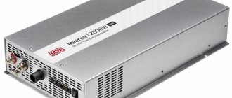
Voltage converters are available in sufficient quantities in stores.
The third option is, rather, a stabilizer based on two converters. First, the standard 220 V is converted to 12 V, then back to 220 V. This double conversion allows you to have an ideal sine wave at the output. Such devices are necessary for the normal operation of most electronically controlled household appliances. In any case, when installing a gas boiler, it is strongly recommended to power it through just such a converter - its electronics are very sensitive to the quality of power, and replacing the control board costs about half the boiler.
When is a voltage converter needed?
You can turn on any electronic device using even one battery of sufficient power. You just need to connect a voltage converter (VC) to it. This device will provide your apartment or house with electricity for several hours.
In what cases is the converter used:
- to perform work in places where there is no electricity (for example, in the field) - the device converts the DC voltage of 12 volts of the battery into alternating voltage 220 V with the required characteristics;
- when protecting objects, so that a building, parking lot or office is not left unprotected due to power surges;
- in case of long business trips or trips - for example, for nomads, truckers and motor tourists.
Inverters are often used in industrial and home environments. These are converters that, after current appears in the network, automatically switch to another mode and begin charging the batteries.
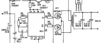
Pulse converter 12-220V 300 W
This circuit is simple, the parts are available, most of them can be removed from a computer power supply or purchased at any radio store. The advantage of the circuit is its ease of implementation, the disadvantage is the non-ideal sine wave at the output and the frequency is higher than the standard 50 Hz. That is, devices that require power supply cannot be connected to this converter. You can directly connect not particularly sensitive devices to the output - incandescent lamps, iron, soldering iron, phone charger, etc.
The presented circuit in normal mode produces 1.5 A or pulls a load of 300 W, at a maximum of 2.5 A, but in this mode the transistors will noticeably heat up.
Voltage converter 12-220 V: converter circuit based on a PWM controller
The circuit was built on the popular TLT494 PWM controller. Field-effect transistors Q1 Q2 should be placed on radiators, preferably separate ones. When installing on one radiator, place an insulating gasket under the transistors. Instead of the IRFZ244 indicated in the diagram, you can use IRFZ46 or RFZ48, which are similar in characteristics.
The frequency in this 12 V to 220 V converter is set by resistor R1 and capacitor C2. The values may differ slightly from those shown in the diagram. If you have an old non-working power supply for your computer, and it contains a working output transformer, you can put it in the circuit. If the transformer is not working, remove the ferrite ring from it and wind the windings with copper wire with a diameter of 0.6 mm. First, the primary winding is wound - 10 turns with the output from the middle, then, on top - 80 turns of the secondary.
As already said, such a 12-220 V voltage converter can only work with a load that is insensitive to power quality. To be able to connect more demanding devices, a rectifier is installed at the output, the output voltage of which is close to normal (diagram below).
A rectifier is added to improve output characteristics
The circuit shows high-frequency diodes of the HER307 type, but they can be replaced with the FR207 or FR107 series. It is advisable to select containers of the specified size.
How does an inverter work?
The basis of a car inverter is a generator with pulse width modulation (PWM). This device runs on a 12-volt battery and produces rectangular pulses (meander) with variable duty cycle (ratio of time when voltage is present/absent). When the duty cycle is one, the inverter provides maximum current. The lower the duty cycle, the correspondingly lower the current. In this case, the output voltage always corresponds to 220 volts. The generator operating frequency is from 50 kilohertz to 5 megahertz, depending on the circuit and details. The conversion of high-frequency voltage into low-frequency (50 hertz) occurs by smoothing the meander in the oscillating circuit formed by the transformer and capacitor, as well as filtering harmonics. After all, the PWM generator not only creates an alternating voltage of 220 volts with a high frequency, but thanks to the changing duty cycle, it modulates the output voltage with a sinusoidal signal with a frequency of 50 hertz.
When the inverter is operating without load, the duty cycle of the PWM generator signals is minimal, and the output voltage is 220V. Connecting a load leads to an increase in current and a voltage drop at the device output below 220v. The feedback system compares the output voltage with a given standard, and then sends a signal to the generator that increases the duty cycle of the pulses. Due to this, the output power increases and the voltage rises. When the load is turned off, the output voltage rises above 220 volts, after which the feedback system reduces the duty cycle of the pulses until the voltage returns to normal. Changing the duty cycle and output current increases the load on the battery, so its voltage often drops below 12 volts. In this case, the feedback circuit further increases the duty cycle, up to unity.
Often, a home-made converter, which does not provide feedback, reacts to connection to a discharged battery by reducing the output voltage. Therefore, they are not very suitable for powering an amplifier or laptop, but they can quite ensure the functioning of devices with a reactive load - hand-held power tools, lamps, boilers.
If a converter is needed to power an amplifier, receiver, TV or laptop, then you cannot do without feedback. Some complexity of the circuit is compensated by the fact that the feedback compensates for voltage drops, thereby ensuring the normal operation of the amplifier or other devices.
Scheme selection
There are a huge number of device diagrams posted on the Internet that convert the energy of a car battery (12 volts) into an alternating voltage of 220 volts and are suitable for making with your own hands. Therefore, it is necessary to choose a circuit based on access to the element base and experience with such devices. If there is a radio parts store near you, then you can find out from them which controllers and power transistors are most available and select the most suitable circuit for them. You can also use the parts that are in any computer power supply. From there you can take:
- controller (PWM generator);
- ferrite ring for transformer;
- power transistors;
- capacitors;
- resistors;
- filter chokes.
If you are not confident that you can make a complex feedback device with your own hands, assemble a 12 → 220 volt inverter based on a 50 Hz multivibrator. The transformer for it can be removed from an old transistor TV or uninterruptible power supply (UPS). Such an inverter takes up much more space than a high-frequency device, but it is easier to set up and parts for it are easier to find.
Circuit example
Inverter on a chip
This 12-220 V voltage converter is assembled on the basis of a specialized KR1211EU1 microcircuit. This is a generator of pulses that are removed from outputs 6 and 4. The pulses are antiphase, with a short time interval between them to prevent the simultaneous opening of both keys. The microcircuit is powered by a voltage of 9.5 V, which is set by a parametric stabilizer on a D814V zener diode.
Also in the circuit there are two high-power field-effect transistors - IRL2505 (VT1 and VT2). They have a very low open resistance of the output channel - about 0.008 Ohms, which is comparable to the resistance of a mechanical key. Permissible direct current is up to 104 A, pulsed current is up to 360 A. Such characteristics actually make it possible to obtain 220 V with a load of up to 400 W. Transistors must be installed on radiators (with a power of up to 200 W it is possible without them).
12-220 V boost converter circuit
The pulse frequency depends on the parameters of resistor R1 and capacitor C1; capacitor C6 is installed at the output to suppress high-frequency surges.
It is better to take a ready-made transformer. In the circuit, it is turned on in reverse - the low-voltage secondary winding serves as the primary, and the voltage is removed from the high-voltage secondary.
Possible replacements in the element base:
- The D814V zener diode indicated in the circuit can be replaced with any one that produces 8-10 V. For example, KS 182, KS 191, KS 210.
- If there are no capacitors C4 and C5 of type K50-35 at 1000 μF, you can take four 5000 μF or 4700 μF and connect them in parallel,
- Instead of an imported capacitor C3 220m, you can supply a domestic one of any type with a capacity of 100-500 µF and a voltage of at least 10 V.
- Transformer - any with a power from 10 W to 1000 W, but its power must be at least twice the planned load.
When installing circuits for connecting a transformer, transistors and connecting to a 12 V source, it is necessary to use large cross-section wires - the current here can reach high values (with a power of 400 W up to 40 A).
Concept of car inverter
Is it true that charging through a car cigarette lighter kills batteries?
A car inverter is an electronic device in which the incoming 12V DC current is converted into a series of pulses supplied to a transformer device with a step-up or step-down function. When using a step-down transformer at the output of the device, the pulse sequence is rectified using an RC filter to produce a lower voltage DC current. This 24 12 voltage converter is used by drivers of trucks and other types of special equipment whose on-board voltage is 24 volts. It allows you to charge mobile phones and other similar devices.
If it is necessary to obtain an AC converter at the output of a car, the design of the device becomes more complicated. Simply increasing the voltage to the required value using a transformer will not be enough here. It is necessary to bring the output signal shape closer to the correct sinusoid to ensure normal functioning of the connected devices. The formation of the output signal is provided by rather complex generation circuits; step-up transformers have quite a large weight and dimensions.
It is necessary to select a voltage stabilizer depending on the purposes for which it is intended to be used. The main criteria for choosing a device with a voltage-stepping transformer are the rated output current and the overload protection function. The first characteristic determines the maximum current value at the output of the device, which it can maintain for a long time without overload. The second ensures that the device is turned off when using devices whose total current consumption significantly exceeds the rated value.
The protection function prevents the device from overheating and the possibility of fire.
If the device is used for a long time, the car battery may be deeply discharged to a state that makes it impossible to start the engine. It is necessary to provide an option to automatically turn off the voltage converter when the battery reaches a critical discharge value.
When choosing a device with a voltage-increasing transformer, the most important characteristics are the shape of the output signal and the speed of operation of the protective device. Cheap devices, especially those made in China, often generate an output signal that quite distorts the correct sine wave. This creates problems for the proper functioning of connected power tools, such as a drill or grinder, whose electric motor induces a powerful magnetic field. There is a huge variety of different models of automotive voltage converters on the market, the prices of which vary greatly. This is due to the difference in operational characteristics.
Inverter with pure sine wave output
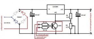
The circuits of daytime converters are complex even for experienced radio amateurs, so making them yourself is not at all easy. An example of the simplest circuit is below.
Inverter circuit 12 200 with pure sine output
In this case, it is easier to assemble such a converter from ready-made boards. How - watch the video. The next video shows how to assemble a 220 volt converter with pure sine wave. Only the input voltage is not 12 V, but 24 V. And this video explains how you can change the input voltage, but still get the required 220 V at the output.
Homemade high power converter
Manufacturing a voltage converter from 12 volts to 220, with a power of 3 kW, will require theoretical knowledge and practical skills in working with radio-electronic components. Some important components, such as the pulse transformer, must be made independently.
The remaining parts can be purchased ready-made. In addition to the transformer, to solve the problem of how to make an inverter you will need the following elements:
- Pulse width modulator - PWM, working directly with semiconductor switches. It is he who sets the operating frequency for the entire circuit, at which the power switches are switched tens of thousands of times within a second.
- Semiconductor transistors. In fact, they are power switches that provide signal amplification and perform all necessary switching. Their main effect is timely opening and closing. Together with PWM, they produce the highest quality sine wave at the output.
- Cooling system. It consists of aluminum radiators, the surface area of which depends on the power of the device. As power increases, a larger radiator is required.
- Required amount of foil material. It serves as the base on which the parts are mounted. On such a board you can assemble any, even the simplest, welding inverter.
- Required brands of capacitors, resistors and other passive elements. The required number of connecting wires with a pre-calculated cross-section.
In some cases, electromagnetic relays may be needed for switching actions. If necessary, they can be used as power switches, but the switching speed in this case will be much lower.
In any case, a homemade device 12 - 220 will cost much less than a factory inverter. However, everyone who has the means prefers to purchase branded devices in a beautiful case, with all the necessary connectors for connecting consumers. Although, some types of converters, developed independently, may surpass the characteristics of their factory counterparts.
Design and principle of operation
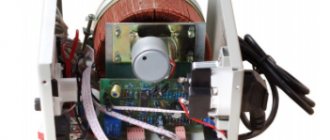
The main element for some modifications of the device is an uninterruptible power supply unit. Its job is to maintain the required voltage in the network using the battery. When the power goes out, the UPS runs on battery power, and the electricity it generates goes to the inverter and from it to the electrical appliance.
Connection diagram
In addition, the voltage converter includes a charger from which the batteries are recharged. And another element of the voltage-frequency converter is the microcontroller. It controls the voltage parameters and, depending on this, gives a command to disconnect or connect the battery.
The struggle for a sine wave - we analyze typical circuits
Voltage inverters are used everywhere today, both by motorists who want to use household appliances away from home, and by residents of autonomous homes powered by solar energy. And in general, we can say that the complexity of the converter device directly determines the width of the range of current collectors that can be connected to it.
Unfortunately, pure “sine” is present only in the main power supply network; it is very, very difficult to achieve conversion of direct current into it. But in most cases this is not required. To connect electric motors (from drills to coffee grinders), a pulsating current with a frequency of 50 to 100 hertz without smoothing is sufficient.
ESL, LED lamps and all kinds of current generators (power supplies, chargers) are more critical to the choice of frequency, since their operating circuit is based on 50 Hz. In such cases, microcircuits called a pulse generator should be included in the secondary vibrator. They can switch a small load directly, or act as a “conductor” for a series of power switches in the inverter output circuit.
But even such a cunning plan will not work if you plan to use an inverter to provide stable power to networks with a mass of heterogeneous consumers, including asynchronous electrical machines. Here, pure “sine” is very important and only frequency converters with digital signal control can implement this.
