Making homemade voltage stabilizers is a fairly common practice. However, for the most part, stabilizing electronic circuits are created that are designed for relatively low output voltages (5-36 volts) and relatively low powers. The devices are used as part of household equipment, nothing more.
We will tell you how to make a powerful voltage stabilizer with your own hands. The article we have proposed describes the process of manufacturing a device for working with a network voltage of 220 volts. Taking into account our advice, you can handle the assembly yourself without any problems.
How to make transformers T1 and T2?
The first transformer T1 with a power of 3 kW is manufactured using a magnetic core with a cross-sectional area (CSA) of 187 sq. mm. And three wires PEV-2:
- For the first wrapping, the PPS is only 0.003 square meters. mm. Number of turns – 8669;
- For the second and third windings, the PPS is only 0.027 sq. mm. The number of turns is 522 on each.
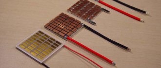
If you don’t want to wind the wire, then you can purchase two TPK-2-2×12V transformers and connect them in series, as in the figure below.
To make an autotransformer with a second power of 6 kW, you will need a toroidal magnetic core and PEV-2 wire, from which a wrap of 455 turns will be made. And here we need bends (7 pieces):
- Wrapping 1-3 bends from wire with PPS 7 sq. mm;
- Wrapping 4-7 bends from wire with PPS 254 sq. mm.
Taps are made on turns (counting from bottom to top): 203, 232, 266, 305, 348, 398. From the network, voltage should be supplied to turn No. 266.
What to buy?
Buy in an electrical and radio equipment store (designation in brackets in the diagram):
- 7 optocoupler triacs MOC3041 or 3061 (U from 1 to 7);
- 7 simple triacs BTA41-800B (VS from 1 to 7);
- 2 LEDs DF005M or KTs407A (VD 1 and 2);
- 3 resistors SP5-2, 5-3 possible (R 13, 14, 25);
- Current equalizing element KR1158EN6A or B (DA1);
- 2 comparing devices LM339N or K1401CA1 (DA 1 and 2);
- Switch with fuse;
- 4 film or ceramic capacitors (C 4, 6, 7, 8);
- 4 oxide capacitors (C 1, 2, 3, 5);
- 7 resistances to limit the current, at their terminals it should be equal to 16 mA (R from 41 to 47);
- 30 resistances (any) with a tolerance of 5%;
- 7 resistances C2-23 with a tolerance of 1% (R from 16 to 22).
How to make transformers T1 and T2?
The first transformer T1 with a power of 3 kW is manufactured using a magnetic core with a cross-sectional area (CSA) of 187 sq. mm. And three wires PEV-2:
- For the first wrapping, the PPS is only 0.003 square meters. mm. Number of turns – 8669;
- For the second and third windings, the PPS is only 0.027 sq. mm. The number of turns is 522 on each.
If you don’t want to wind the wire, then you can purchase two TPK-2-2×12V transformers and connect them in series, as in the figure below.
To make an autotransformer with a second power of 6 kW, you will need a toroidal magnetic core and PEV-2 wire, from which a wrap of 455 turns will be made. And here we need bends (7 pieces):
- Wrapping 1-3 bends from wire with PPS 7 sq. mm;
- Wrapping 4-7 bends from wire with PPS 254 sq. mm.
Taps are made on turns (counting from bottom to top): 203, 232, 266, 305, 348, 398. From the network, voltage should be supplied to turn No. 266.
220V voltage stabilizer for home: types and characteristics of devices
Voltage fluctuations in the electrical network can be observed for various reasons: in winter, this is the widespread inclusion of electric heaters for additional heating, which leads to a decrease in voltage; in the summer, an increase in voltage can be triggered by lightning, possibly striking substations. 220V voltage stabilizers for the home are designed specifically to smooth out fluctuations and voltage drops in the network.
Helpful advice! To significantly extend the life of household and electronic appliances, you should use them in power-saving mode, connecting them through a voltage stabilizer.
To find out how to choose 220V voltage stabilizers for your home, you should familiarize yourself with the types and advantages of these devices. Manufacturers of these devices offer several types of stabilizers.
Stationary stabilizers are connected to the distribution panel, and local stabilizers are connected directly to electrical appliances
Electronic (relay) rectifiers
Such converters are highly efficient and quickly respond to fluctuations in the network. They contain transformer windings with numerous branches. Resistant to voltage surges due to the absence of mechanical elements in the device.
Advantages of a 220V electronic voltage stabilizer for the home:
- compact size;
- silent operation;
- wide conversion range;
- work with overload (up to 110% of the nominal);
- reasonable price, long service life.
The disadvantage is the low accuracy of the output voltage (error up to 8%). If a lot of electricity is consumed in the house, such a stabilizer is not practical.
Electronic (relay) voltage stabilizer IEK CHP1-1-1 kVA
Electromechanical stabilizers
The design of this rectifier involves an electric motor inside the coil. It drives a winding of graphite-tipped brushes. Sufficiently powerful devices are characterized by smooth regulation and high-precision output voltage.
- high performance;
- overload tolerance (up to 200%);
- silent operation;
- affordable price;
- durability.
Of the negative points:
- low leveling speed;
- need for maintenance;
- periodic failure of mechanical elements;
- inability to work at negative temperatures below 5°C.
Internal structure of an electromechanical voltage stabilizer
Ferroresonant voltage stabilizers
Their device contains two or more coils of wire strung on metal capacitor rods. Advantages:
- high speed of response to fluctuations in the network;
- operation in a temperature range from -40°С to +50°С;
- durability of use.
Disadvantages of 220V ferroresonant voltage stabilizers for home:
- price;
- large dimensions;
- distortion of output indicators;
- noisy work;
- vulnerability to frequency changes;
- impossibility of functioning at a load below the nominal load by 10-20%.
Operating principle of a ferroresonant voltage stabilizer
Types of stabilizers
All industrial designs of such equipment can be divided into two large groups:
- electromechanical;
- pulsed.
Electromechanical
The operation of electromechanical devices is based on a servo drive, which is capable of changing the number of winding turns (and therefore the output voltage) by moving a conductive slider along a rheostat. Such devices are cheaper than all other models and have very good stabilization performance. However, they are more likely to break due to the presence of many mechanical parts.
But their main disadvantage is the response speed. Due to the fact that the drive does not move the current collector instantly, the stabilization delay can be up to 0.1 seconds, which is catastrophically long for devices that are sensitive to differences. In other words, such a stabilizer may simply not have time to protect modern electronics. In addition, due to the presence of mechanical parts, reproducing such a device at home is a non-trivial task.
Pulse
Stabilizers are called pulse stabilizers, the operation of which is based on the principle of accumulating current and distributing it to the consumer in fragments - pulses. These time intervals allow the system to accumulate the required current in the capacitors, and then provide stabilized power. Such devices also include devices whose operation is based on triacs and thyristors.
Such devices are more expensive than their electromechanical counterparts, but they are also much more reliable - there are no rubbing or moving parts, which means that, in fact, there is nothing to break. True, their stabilization indicators are worse - they are only capable of a proportional increase or decrease in input indicators. But the response speed is up to 20 milliseconds, and this is enough to protect even the most sensitive household electrical appliances. In addition, such a device can be assembled with your own hands, having the necessary skill and element base.
In addition to separation according to the principle of stabilization, there is a separation into single- and three-phase devices. But due to the fact that single-phase power is usually used at home, we do not take three-phase devices into account.
Advantages of a household rectifier
By design and principle of operation, a double conversion stabilizer has a number of positive properties. A household inverter has the following qualities that affect the performance of the device:
- Extended input voltage indicator in the range of 115−300.
- Stabilization of the output voltage up to 220 V in case of a sharp current surge.
- Low noise threshold during operation of the device.
- Compact body dimensions and low weight.
- Filtering of high-frequency interference and emissions.
- Efficiency > 90%.
- Low accuracy of input voltage normalization.
- Operational regulation of electric current strength.
- Unpretentiousness to maintenance and operating conditions.
Which is better: relay or triac
If we compare a triac stabilizer and a relay or thyristor stabilizer, then the first one is undoubtedly a more reliable, durable and safe device. This is explained by the absence of switches with moving contacts, the presence of a control board, a powerful autotransformer and power triac switches. The only drawback of triac stabilizers, compared to other devices, is their high cost, which over time justifies itself with a long service life and high reliability.
Thus, the device described in this article allows us to effectively deal with such a problem for many owners of apartments, country houses and country houses as voltage surges in the electrical network. The use of a stabilizer allows you to reduce to zero the risk of breakdown of electrical appliances and subsequent expensive repairs from short-term power surges in the network. The big difference in the price of such devices, compared to analogues, is several times less than the cost of repairing or purchasing new devices and equipment damaged by surges in unstable network electric current.
Advantages and disadvantages, differences from factory models
If we list the advantages of stabilizers made independently, the main advantage is low cost. Manufacturers of devices often inflate prices, and in any case, their own assembly will cost less.
Another advantage can be determined by such a factor as the ability to easily repair the device with your own hands. After all, who, if not you, knows better about a device assembled with your own hands.
In the event of a breakdown, the owner of the device will immediately find the faulty element and replace it with a new one. Easy replacement of parts is created by the fact that all parts were purchased in a store, so they can be easily purchased again at any store.
The disadvantage of a self-assembled voltage stabilizer is its complex configuration.
Assembly features of the device for voltage equalization
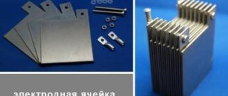
The current stabilizing device microcircuit is installed on a heat sink, for which an aluminum plate is suitable. Its area should not be less than 15 square meters. cm.
A heat sink with a cooling surface is also necessary for triacs. For all 7 elements, one heat sink with an area of at least 16 square meters is sufficient. dm.
In order for the AC voltage converter we manufacture to work, you will need a microcontroller. The KR1554LP5 microcircuit copes with its role perfectly.
You already know that you can find 9 flashing diodes in the circuit. All of them are located on it so that they fit into the holes that are on the front panel of the device. And if the stabilizer body does not allow their location, as in the diagram, then you can modify it so that the LEDs come out on the side that is convenient for you.
Now you know how to make a 220 volt voltage stabilizer. And if you have already had to do something similar before, then this work will not be difficult for you. As a result, you can save several thousand rubles on the purchase of an industrial stabilizer.
Let's start assembly
Since the most effective device is a triac device, let’s talk about how to make a similar stabilizer with your own hands.
It is important to emphasize that this type of model will be able to equalize the supplied current under the condition that the voltage is in the range of 130-270 V. Components will also be required. Tools you need are tweezers and a soldering iron.
Comments:
Cherevaty
Informative article, thank you. The diagrams are detailed and easy to read. There will be something to do on vacation. I want to throw such a stabilizer under a homemade wind station that powers a light bulb in a gazebo. Do you think the scheme will work?
Gaivoronsky
I assembled everything according to the diagram - everything works, thanks to the author. I will continue to experiment with a soldering iron and printed circuit boards.
Slavon
Uff... Does anyone know where all the parts can be bought? So that in one place you don’t have to overpay for the delivery of one relay, otherwise the stabilizer will turn out to be more expensive than a store-bought one
Alex
Slavon, yes, all these parts are sold on any piece of hardware. Don't bother. In any case, they are cheaper on the market, and you can buy used ones (but only if they are Soviet) - so in general the price turns out to be a pittance
Oleg Kyiv
The language of presentation certainly deserves special attention.
Vyacheslav
How were you able to repeat the design if there is no data on the magnetic circuit for the T2 transformer?
Sergey
How to convert the divider to a voltage of 100-250 volts?
Commercial benefits from installing a voltage stabilizer
Domestic power grids are physically very worn out, and in some places they are morally outdated. And there are more and more consumers. Installing stabilizers is beneficial for several reasons:
Modern technology is equipped with electronic components, which require high-quality nutrition. To ensure that it does not fail or undergo expensive repairs, it is necessary to install a stabilizer; lower voltage entails greater current consumption from the network
You have to pay more for energy consumption. The benefit of the stabilizer is obvious; Increased voltage can lead to short circuits, overheating of wires and fire. Without a stabilizer in this case, material and moral damage can be colossal, or even irreparable; at normal voltage, sudden impulses from lightning, personnel errors, and phase imbalance during rush hour can also occur.
In all these and other unforeseen cases, a voltage stabilizer will help save time, money and nerves.
Disadvantages of ET models offered on the market
Cheap models do not have special overload protection.
Despite the economical and well-developed design, electric power supplies have a number of disadvantages, which are usually classified as:
- lack of special overload protection in the simplest Chinese models;
- the resulting need for mandatory modification of the scheme;
- Many market samples do not have an input filter device, which forces them to add a smoothing electrolytic capacitor (it is placed after the “powerful” choke).
The listed disadvantages usually include the “hard” operating mode of high-voltage transistors connected according to a key circuit.
In the event of an accidental output short circuit (SC), these elements simply “burn out,” which leads to the need for an urgent update of the entire electronic module. Often, the rectifier based on semiconductor diodes also breaks down and also needs to be replaced.
Advantages
Low cost
It is precisely because of their low price, relative to other types of stabilizers, that relay models are so popular. At the same time, in other respects, they completely cover the needs of the modern consumer in most cases.
Quite fast stabilization speed, on average 5-30 ms
Relay stabilizers react to changes in incoming voltage at high speed, and allow you to protect your electrical equipment even during sudden drops or surges
Simplicity and maintainability
Possessing a simple, understandable architecture, relay stabilizers do not have a mass of complex components that could fail. There are not many possible problems and all of them have been studied and described, are easily diagnosed and can be corrected at home, even if you have only superficial knowledge and skills in electrical repair.
Manufacturing stages
To assemble a 220V voltage stabilizer for your home with your own hands, you first need to prepare a printed circuit board measuring 115x90 mm. It is made of foil fiberglass. The layout of the parts can be printed on a laser printer and transferred to the board using an iron.
Let's watch the video, a homemade simple device:
electrical circuit diagram
Next we move on to assembling the transformers. For one such element you will need:
- magnetic core with a cross-sectional area of 1.87 cm²;
- three PEV-2 cables.
The first wire is used to create one winding, and its diameter is 0.064 mm. The number of turns should be 8669.
The two remaining wires will be needed to make other windings. They differ from the first one in diameter being 0.185 mm. The number of turns for these windings will be 522.
If you want to simplify your task, you can use two ready-made TPK-2-2 12V transformers. They are connected in series.
In the case of making these parts yourself, after one of them is ready, they move on to creating the second. It will require a toroidal magnetic circuit. For the winding, choose the same PEV-2 as in the first case, only the number of turns will be 455.
Also in the second transformer you will have to make 7 taps. Moreover, for the first three, a wire with a diameter of 3 mm is used, and for the rest, buses with a cross-section of 18 mm² are used. This will help prevent the transformer from heating up during operation.
connection of two transformers
It is better to purchase all other components for a device you create yourself in a store. Once everything you need has been purchased, you can begin assembly. It is best to start by installing a microcircuit that acts as a controller on a heat sink, which is made of aluminum platinum with an area of more than 15 cm². Triacs are also mounted on it. Moreover, the heat sink on which they are supposed to be installed must have a cooling surface.
Next you need to install LEDs on the board. Moreover, it is better to choose blinking ones. If it is not possible to arrange them according to the diagram, then you can place them on the side where the printed conductors are located.
If assembling a 220V triac voltage stabilizer with your own hands seems complicated to you, then you can opt for a simpler linear model. It will have similar properties.
The effectiveness of a handmade product
What pushes a person to make this or that device? Most often - its high cost. And in this sense, a voltage stabilizer assembled with your own hands is, of course, superior to a factory model.
In addition, all the parts for such a device were previously purchased in the store, so if they fail, you can always find a similar one.
If we compare the reliability of a stabilizer assembled with our own hands and manufactured at an enterprise, then the advantage is on the side of factory models. At home, it is almost impossible to develop a model with high performance, since there is no special measuring equipment.
Conclusion
There are different types of voltage stabilizers, and some of them are quite possible to make with your own hands. But to do this, you will have to understand the nuances of the operation of the equipment, purchase the necessary components and carry out their proper installation. If you are not confident in your abilities, then the best option is to purchase a factory-made device. Such a stabilizer costs more, but the quality is significantly superior to models assembled independently.
PCB manufacturing
For a triac current converter, you need a printed circuit board on which all the elements will be placed. Its size: 11.5 by 9 cm. To make it you will need fiberglass, covered with foil on one side.
The board can be printed on a laser printer, after which an iron will be used. It is convenient to make a board yourself using the Sprint Loyout program. A diagram of the placement of elements on it is shown below.
Connection errors
1
You may have everything connected perfectly and the diagram followed, but the stabilizer will constantly heat up and turn off, or errors will appear on its display.
Read in detail about where you can and where you should never place this device in the article “Where to install a voltage stabilizer in the house.”
2
Of course, this point can hardly be called a mistake. Moreover, 90% of consumers do just that.
However, this switch can really save your device from failure.
First you turn off the machines on the stabilizer panel.
Then move the switch itself to the TRANSIT or BYPASS position.
And only then turn on the machines again.
Many people forget about this and switch under load. Which ultimately leads to breakdowns.
With a 3-position automatic machine this is impossible. You automatically switch the voltage, without any manipulation on the stabilizer. And all this with one key!
There is no need to remember any sequence. So this procedure can be safely trusted to any family member.
3
You can choose a smaller cross-section only when powering individual electrical receivers.
If your whole house is sitting on a stabilizer, then please follow the input parameters according to the entire general house load.
4
For some reason, many people forget that often the entire load of your home passes through the stabilizer. Exactly the same as on the automatic input.
At the same time, in the electrical panel all the wires are crimped, even on light switches with minimal currents, but on the terminal blocks of the stabilizer or its circuit breakers, you can always find a bare wire simply pressed in with a screw.
Therefore, do not skimp and purchase the appropriate tips along with the device in advance.
5
Sometimes after connecting the stabilizer, the input machine starts to knock out. In this case, without a stabilizer, everything is fine and nothing is turned off.
Many people immediately blame it on an incorrect connection diagram or a defect in the device. They take it for warranty repairs, etc.
But the reason may be completely different. If your voltage is too low, 150-160V, then when you increase it to the standard 220-230V, the current in the network will increase significantly.
Hence all the problems
Please pay attention to this before you take it back to the store.
Sources - https://cable.ru, Kabel.RF
Connecting single-phase consumers
The most rational approach to power supply to a private home would be to select a separate group from the total number of consumers, which requires stable voltage parameters.
Typically, increased stability is required for televisions, refrigerators, office equipment and communications equipment. Other household appliances, especially those with heating elements, do not necessarily need to be connected to the stabilizer. Electric kettles and electric boilers will still work, since voltage drops for them do not play a decisive role in the performance of basic functions. In the home panel, after the electric meter, protective equipment is installed - a differential circuit breaker or an RCD with a circuit breaker. From them, phase and zero are supplied by separate cables to the input terminals of the stabilizer. The device body is also connected with a separate wire to the PE bus installed in the panel. From the output terminals of the stabilizer, a phase and a working zero are supplied to the consumer. The protective zero is connected to the PE bus.
The next option involves connecting several groups of consumers to the stabilizer at once. In the simplified circuit, protective grounding is not used, and the stabilizer is connected through one terminal of the working zero. The operation of the scheme is best viewed using the example of three consumer groups.
Inside the switchboard, after all the protective devices, it is necessary to create a working zero bus, which is connected to all consumers, including the voltage stabilizer. The phase input wire from the protection is connected to the input terminal of the device, and the outgoing wire is connected to the output. The second end of the phase wire is inserted into the distribution panel to connect the loads in parallel. All consumer groups are connected via circuit breakers.
If the stabilizer has two terminals for the working zero, the following changes will occur in the circuit:
- The working zero bus remains connected to consumers, but it will no longer be connected to protective devices.
- The neutral wire from the protective devices will be connected to the input terminal of the working zero of the stabilizer.
Determining the type of protection
Today, stabilizers are divided into 2 main types:
- stationary devices for voltage stabilization, their installation is done for the whole house;
- portable models, they can stabilize the operation of just a few electrical devices.
Also, stabilizers for stationary use are divided into single-phase and three-phase, it all depends on the conditions in which they are planned to be used. In your house or apartment, it would be more appropriate to install and connect a stabilizer near the electricity distribution board; with this step you can prevent failures and overloads of the entire network.
Selection rules
Before deciding on the choice of a stabilizer based on the type of power supply, it is important to decide in which networks it is intended to be used. If you plan to use it in an apartment in a city house, the owner will need a standard single-phase device
If the buyer intends to use it at the dacha, where there is a 380 Volt power supply, only a three-phase sample will do.
Before going to the store, it is important to familiarize yourself with the manufacturers of these devices and choose a company that has a good reputation. In this case, it does not matter whether it is a domestic or foreign company, since our manufacturers are also capable of making competitive models
Choosing a voltage stabilizer for a computer
A computer consists of a system unit and a monitor. Therefore, the power must be summed up. Also, if the stabilizer also includes additional devices (scanner, printer, etc.), then all the power must be summed up and the resulting result compared with the range of ratings of the voltage stabilizers in question. As a rule, for a home computer you can choose a stabilizer with a power of no more than 1000 W.
For a computer, I also recommend using Smart UPS (interactive UPS) instead of a stabilizer. They contain a stabilization function (relay type) and have a battery. Thus, the voltage will be relatively stable and the reserve will be ensured.
What you need to connect
In addition to the stabilizer itself, you will need a number of additional materials:
three-core cable VVGnG-Ls
The cross-section of the wire must be exactly the same as on your input cable, which comes to the main input switch or circuit breaker. Since the entire load of the house will go through it.
three position switch
This switch, unlike simple ones, has three states:
123
You can also use a regular modular circuit breaker, but with this scheme, if you need to disconnect from the stabilizer, you will have to completely de-energize the entire house each time and reconnect the wires.
There is, of course, a bypass or transit mode, but in order to switch to it, you need to follow a strict sequence. This will be discussed in more detail below.
With this switch, you completely cut off the unit with one movement, and the house remains with light directly.
PUGV wire of different colors
You must clearly understand that the voltage stabilizer is installed strictly before the electric meter, and not after it.
Not a single energy supplying organization will allow you to connect in another way, no matter how much you prove that by doing so, in addition to the electrical equipment in the house, you want to protect the meter itself.
The stabilizer has its own idle speed and also consumes energy, even when operating without load (up to 30 W/h and above). And this energy must be taken into account and calculated.
The second important point is that it is highly desirable that in the circuit up to the connection point of the stabilization device there is either an RCD or a differential circuit breaker.
This is recommended by all manufacturers of popular brands Resanta, Sven, Leader, Shtil, etc.
It could be an introductory automatic differential for the whole house, it doesn’t matter. The main thing is that the equipment itself is protected from current leakage
And breakdown of the transformer windings to the housing is not such a rare thing.
Principle of operation
Such a stabilizing device works as follows:
- The voltage supplied to the device from the external network is measured by the control board (controller) using a special sensor;
- Based on the measurements obtained, the controller makes a decision to adjust the voltage;
- The controller sends the corresponding signal to the input triacs;
- Using the signal sent to the triacs by the controller, a voltage equalized to a certain value is supplied;
- Using an autotransformer located in the housing, the voltage supplied from the external network is equalized to the value necessary for the normal operation of electrical appliances.
This multi-step process takes a fraction of seconds. At the same time, unlike relay models, the presence of triacs makes it possible to turn on and off the transformer windings silently and very quickly.
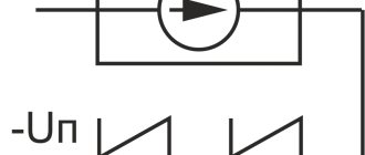
How will this device work?
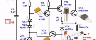
After the drive of the node with the pending load (C1) is connected to the network, it is still discharged. Transistor VT1 turns on, and 2 and 3 close. Through the latter, current will subsequently flow to the LEDs and optocoupler triacs. But while the transistor is closed, the diodes do not give a signal, and the triacs are still closed: there is no load. But the current is already flowing through the first resistor to the storage device, which begins to accumulate energy.
The process described above takes 3 seconds, after which the Schmitt trigger, based on transistors VT 1 and 2, is triggered, after which transistor 3 is turned on. Now the load can be considered open.
The output voltage from the third winding of the transformer on the power supply is equalized by the second diode and capacitor. Then the current is directed to R13, passes through R14. At the moment, the voltage is proportional to the voltage in the network. Then the current is supplied to non-inverting comparators. Immediately, the inverting comparing devices receive an already equalized current, which is supplied to resistances from 15 to 23. Then a controller is connected to process the input signals on the comparison devices.
Advantages and disadvantages
The advantages of such a device include:
- High performance - the device, thanks to the presence of high-speed switching simulators, is able to respond very quickly to voltage surges in the network, smoothing them out to the required value;
- Wide range of input voltage - stabilizers of this type are capable of operating at input voltage values from 95 to 275 V (for a single-phase model), from 260 to 470-471 V (for three-phase stabilizers);
- High accuracy of stabilization - the output voltage produced by such devices has a maximum fluctuation within 1.5% (3.3-5.7 V), which does not have a negative impact on the operation of the devices connected to it.
- Monitoring the values of the input and output potential difference with an error of no more than 0.5%;
- High efficiency - thanks to the use of a triac, the value of this indicator for most models reaches 95-97%;
- Silence – the absence of relay switches and moving contacts in the design of the stabilizer allows it to operate almost silently;
- Small dimensions - stabilizers assembled on triacs, compared to relay ones, are small in size and can be compactly placed on the floor or wall of even the smallest room;
- Long service life - most modern high-quality models can normally perform their functions for 10 years or more;
- High power - various models are capable of ensuring normal operation of connected devices and equipment with a total power of 3 to 10 kW.
The disadvantages of such stabilizers include:
- High cost - high-quality models of stabilizers have a fairly high cost, which is not always affordable for many owners of apartments and houses.
- An abrupt change in the potential difference at the output of the device - this drawback is typical for inexpensive Chinese-made models. It practically does not appear in more expensive analogues.
On a note. Despite the high cost of such devices, their purchase in case of problems with the network voltage will be very profitable and will pay for itself quite quickly - if the stabilizer is missing, serious breakdowns of sensitive household appliances, pumping and heating equipment can occur. In some cases, such surges not only damage devices connected to the network, but also render them inoperable, which requires their replacement, leading to unplanned and significant financial expenses and other inconveniences.
Homemade current equalizer: characteristics
The stabilizer is characterized by two parameters:
- Permissible range of input voltage (Uin);
- Permissible range of output voltage (Uout).
This article discusses the triac current converter because it is highly efficient. For it, Uin is 130-270V, and Uout is 205-230V. If a large input voltage range is an advantage, then for the output it is a disadvantage.
However, for household appliances this range remains acceptable. This is easy to check, because the permissible voltage fluctuations are surges and dips of no more than 10%. And this is 22.2 Volts up or down. This means that it is permissible to change the voltage from 197.8 to 242.2 Volts. Compared to this range, the current on our triac stabilizer is even smoother.
The device is suitable for connecting to a line with a load of no more than 6 kW. It switches in 0.01 seconds.
Additional functions of voltage stabilizers
In addition to the main function of voltage stabilizers - stabilization, there is also the following minimum set of functions and parameters:
Maybe this will be interesting too?
- Output voltage analysis. The stabilizer must be equipped with an information (digital or pointer) display that shows the output voltage. If the stabilizer has an input voltage analysis function, this will be additional useful information.
- At higher ratings (usually from 3000 VA), the “Bypass” function is installed - a function in an electronic device (signal processing, voltage stabilization, etc.) that allows you to switch the input signal directly to the output, bypassing all functional blocks. That is, the ability to turn on the network bypassing the voltage stabilizer. If the voltage has returned to normal or you do not need a stabilizer now, press the lever up and the voltage goes bypassing the stabilization blocks.
- Types of fastening of voltage stabilizers There are two types of fastening of voltage stabilizers - floor and wall versions. Floor-standing design means that the stabilizer is located on the floor or shelf. This arrangement is not always convenient, because especially large denominations cannot be placed on a shelf due to their weight, and they occupy quite large areas on the floor. When mounted, the stabilizers are made flatter for the convenience of customers. In principle, they can also be used in a floor-standing version, only often the information part of the display is in this case “upside down” towards the user.
- Many models on the voltage stabilizer market use a delay button. This is done so that if the voltage in the network disappears or temporarily goes beyond the operating range, the equipment will come to a rest position during this delay time before the next turn on. In many stabilizers, the delay button is offered in several ranges -6, 90, 120 sec. In more modern models, the delay has already become automatic and when it is turned on, it shows the consumer on the display the time the stabilizer is turned on in the form of a countdown.
Nuances of stabilization depending on the voltage supplied to the input
If a voltage of up to 130 Volts is introduced, then a low voltage logical level (LU) is indicated at the comparator terminals. The fourth transistor is open, and LED 1 blinks and indicates that there is a strong dip in the line. You must understand that the stabilizer is not able to produce the required voltage. Therefore, all triacs are closed and there is no load.
If the voltage at the input is 130-150 Volts, then a high LU is observed on signals 1 and A, but for other signals it is still low. The fifth transistor turns on, the second diode lights up. Optocoupler triac U1.2 and triac VS2 open. The load will go along the latter and reach the winding terminal of the second autotransformer from above.
With an input voltage of 150-170 Volts, a high LU is observed on signals 1, 2 and V; on the rest it is still low. Then the sixth transistor turns on and the third diode turns on, VS2 turns on and the current is supplied to the second (if counted from above) winding terminal of the second autotransformer.
The operation of the stabilizer is described in the same way at voltage ranges of 170-190V, 190-210V, 210-230V, 230-250V.
Assembly features of the device for voltage equalization
The current stabilizing device microcircuit is installed on a heat sink, for which an aluminum plate is suitable. Its area should not be less than 15 square meters. cm.
A heat sink with a cooling surface is also necessary for triacs. For all 7 elements, one heat sink with an area of at least 16 square meters is sufficient. dm.
In order for the AC voltage converter we manufacture to work, you will need a microcontroller. The KR1554LP5 microcircuit copes with its role perfectly.
You already know that you can find 9 flashing diodes in the circuit. All of them are located on it so that they fit into the holes that are on the front panel of the device. And if the stabilizer body does not allow their location, as in the diagram, then you can modify it so that the LEDs come out on the side that is convenient for you.
Now you know how to make a 220 volt voltage stabilizer. And if you have already had to do something similar before, then this work will not be difficult for you. As a result, you can save several thousand rubles on the purchase of an industrial stabilizer.
Advantages and disadvantages of a homemade current converter
A homemade stabilizer has three advantages:
- Cheap . All parts are purchased separately, and this is cost-effective compared to the same parts, but already assembled into a single device - a current equalizer;
- Possibility of DIY repair . If one of the elements of the purchased stabilizer fails, you are unlikely to be able to replace it, even if you understand electrical engineering. You simply won’t find anything to replace a worn-out part with. With a homemade device, everything is simpler: you initially bought all the elements in the store. All that remains is to go there again and buy what is broken;
- Easy repair . If you have assembled a voltage converter yourself, then you know 100% of its design and operating principle. And understanding the device and operation will help you quickly identify the cause of stabilizer failure. Once you figure it out, you can easily repair your homemade unit.
The self-produced stabilizer has three serious disadvantages:
- Low reliability . At specialized enterprises, devices are more reliable, since their development is based on the readings of high-precision instrumentation, which cannot be found in everyday life;
- Wide output voltage range . If industrial stabilizers can produce a relatively constant voltage (for example, 215-220V), then home-made analogues can have a range 2-5 times larger, which can be critical for equipment that is hypersensitive to changes in current;
- Difficult setup . If you buy a stabilizer, then the setup stage is bypassed; all you have to do is connect the device and control its operation. If you are the creator of the current equalizer, then you should configure it too. This is difficult, even if you have made the simplest voltage stabilizer yourself.
Operation of the Suntek electromechanical stabilizer
To change the input voltage, an autotransformer is used, which can change the voltage within the required limits. In this case, the voltage at the output of the stabilizer does not go beyond the operating range.
In rural areas, for the safe use of household appliances, a single-phase 220V voltage stabilizer is required, which, in the event of a strong voltage drop in the network, maintains a rated output voltage of 220 volts at the output.
The electrical design has three threshold blocks, built on the principle of a voltage divider, consisting of resistances (R2-VD1-R1, VD5-R3-R6, R5-VD6-R6). In addition, the circuit uses two transistor switches VT1 and VT2 that control relays K1 and K2.
Diodes VD2 and VD3, together with filter capacitance C2, constitute the power source for the entire device. Capacitors C1 and C3 are used to absorb small voltage sags in the AC network. Capacitance C4 and resistor R4 are spark arresting components. To reduce self-induction voltage surges, two semiconductor diodes VD4 and VD7 are introduced into the circuit in the relay windings.
If the network voltage drops below 185 volts, then the relay contacts are turned on as in the diagram. The load voltage will be the sum of the mains voltage plus the voltage boost received from windings II and III of transformer T1.
If the voltage is in the range of 185-205 volts, then the zener diode VD5 is open. Current flows through relay K1, VD5 and resistors R3 and R6. But this current is not enough to trigger relay K1. Due to the voltage drop across resistor R6, VT2 opens. This transistor triggers relay K2 which, with its contacts, switches winding II (voltage booster).
If the network voltage is normal 205-225 volts, then the zener diode VD3 is open. This leads to the opening of VT1, so the second threshold block and VT2 are turned off along with relay K2. But K1 is triggered and with its contacts turns off windings II and III, and therefore the output voltage corresponds to the input.
When the mains voltage level increases above 225 but below 245 volts, the zener diode VD6 opens, opening both. Both relays are activated by winding III T1, connected in antiphase with the mains voltage (i.e. subtracted)). The output will have a normal alternating voltage in the range of 205-225 volts.
Triac-transformer AC voltage stabilizer
In rural areas, and sometimes in cities, significant drops in mains voltage relative to the nominal 230 V often occur. This often leads to refrigerator failures. The efficiency of working with power tools decreases significantly, and the lighting dims. To stabilize the network voltage while maintaining its shape, the author at one time used a relay-transformer stabilizer [1], but from many years of use the contacts of the relays installed in it wore out. It was decided to rework the stabilizer, replacing the electromagnetic relays with triac switches. The load capacity of the proposed stabilizer is 1840 VA.
First of all, let's consider possible circuits of alternating voltage stabilizers based on an autotransformer. In the device according to the diagram shown in Fig. 1a, compensate for the decrease in mains voltage (an unacceptable excess of the nominal value is observed extremely rarely), gradually moving the moving contact of switch SA1 down the circuit. In this case, the voltage on each of the windings of the autotransformer and at the output of the stabilizer is approximately maintained, fluctuating within limited limits. In a stabilizer assembled according to the diagram in Fig. 1b, the mains voltage is constantly supplied to one of the winding taps of the autotransformer, and as the voltage in the network decreases, the moving contact of switch SA1 is moved up.
Rice. 1. Possible circuits of AC voltage stabilizers based on an autotransformer
Let's consider the main features of the above options.
In the device according to the diagram shown in Fig. 1a, the voltage on each of the winding sections is stabilized, which allows its sections II-IV to be used as stable sources of relatively small alternating voltage, for example, to power low-voltage power tools. Switching of autotransformer taps (in a real design using relays or triacs) always, even when the stabilizer is idling, occurs under an inductive or active-inductive load, which is unfavorable for switching devices.
In the device according to the diagram in Fig. 1,b the voltage on the winding sections is not stabilized. In the absence of load, and this is the main situation when working on a refrigerator, switching occurs in idle mode, the wear of the relay contacts is purely mechanical.
The selection criterion for the author was the last difference between the options.
Note that both considered options will become suitable for compensating for an increase in voltage in the network if the output (in Fig. 1, a) or input (in Fig. 1, b) wire is transferred to another tap of the autotransformer winding. In his practice, the author came across a variant of the stabilizer, the diagram of which is shown in Fig. 1, c. When the network voltage is less than or equal to the rated one, it operates in the same way as in the version in Fig. 1, a. When the voltage in the network exceeds the nominal value, the moving contact of switch SA1 is fixed in the upper position according to the diagram, and switch SA2 is moved to position 2.
Let us take as a basis the diagram shown in Fig. 1b, and determine the procedure for calculating the transformation coefficients for various positions of the SA1 switch slider. Let's set the limits for changes in the input voltage and permissible fluctuations in the output voltage. According to the results of observations at the dacha for which the described stabilizer was built, the voltage in the network sometimes dropped to 150 V. This input voltage should correspond to an output voltage of 200 V, at which all household electrical appliances still operate. Therefore, the voltage increase factor with switch SA1 in position 1 should be equal to 200/150 = 1.33. Here and further, I deliberately do not use the term “transformation ratio”, since it is understood as the ratio of the number of turns of the primary winding to the number of turns of the secondary. In this case, it is more logical to use the inverse value - the voltage increase factor.
The number of taps from the autotransformer winding depends on the required accuracy of maintaining the output voltage. As a result of several trial calculations, it was concluded that to maintain it within 210...240 V, four steps are sufficient, including direct connection of the load to the network. A decrease in the voltage in the network to 150 V is considered as an emergency in which the voltage at the load drops to 200 V.
It can be shown that in order to obtain the same limits of change in the output voltage in each position of the switch SA1, the values of the coefficients of increase in these positions must represent a geometric progression. Therefore, if in position 1 the increase coefficient is 1.33, it should be equal to 1.1 in position 3 and 1.21 in position 2. In position 4, the output voltage comes directly from the network and the coefficient is 1.
Let's plot the dependence of the output voltage on the input. To do this, on a sheet of graph paper measuring at least 250×250 mm, draw coordinate axes on a scale of 1 mm/V and draw four straight lines from the origin of coordinates with slope angles of 1; 1.1; 1.21 and 1.33. Let us select sections of these straight lines located between the horizontal lines corresponding to the output voltage of 210 and 240 V. From the points of intersection of the lines with a slope of 1.33, 1.21 and 1.1 with the horizontal of 240 V, we lower the vertical straight lines until they intersect with the nearest lines with a slope of 1.21, 1,1 and 1. From the points of intersection of these inclined lines with the horizontal 210 V, we will draw similar straight lines upward.
In Fig. Figure 2 shows a fragment of the resulting drawing. When the input voltage is more than 220 V, switch SA1 is in position 4, and the output voltage is supplied to the output without change. When the network voltage decreases to 210 V, the switch is set to position 3, the transmission coefficient increases to 1.1, and the output voltage jumps to 231 V. With a further decrease in the network voltage to approximately 191 V, the output will decrease to 210 V, the switch will be set to position 2, the output voltage will rise again to 231 V. A similar process will occur when the input voltage decreases to 173 V. When it decreases to 150 V, the output voltage, as mentioned above, will drop to 200 V.
Rice. 2. Graph of output voltage versus input voltage
When the input voltage increases, switching occurs when the input voltage reaches the values of 180, 198 and 218 V, while the output decreases abruptly each time from 240 to 218 V. Thus, when the mains voltage changes from 158 to 240 V, the output is maintained in the range from 210 to 218 V 240 V.
To prevent surges from occurring too frequently when the network voltage fluctuates around the switching thresholds, hysteresis is necessary. The described algorithm for switching winding taps provides it sufficiently. It is easy to see that while maintaining the number of stages, even a slight increase in the accuracy of maintaining the output voltage due to narrowing the hysteresis loops will lead to a significant decrease in their width, which is unacceptable. Therefore, to achieve greater accuracy, it is necessary to increase the number of steps of changing the coefficient. Note also that the reasoning for choosing its values is also valid for devices according to the circuits in Fig. 1,a and fig. 1, c.
The schematic diagram of the stabilizer is shown in Fig. 3, and the diagram of its control unit is in Fig. 4. The autotransformer is composed of three identical transformers T1-T3 - TPP319-127/220-50 [2], the primary windings of which are connected in parallel, and the series connection of the secondary windings provides the required voltage increase factors.
Rice. 3. Schematic diagram of the stabilizer
Rice. 4. Diagram of the stabilizer control unit
When switch SA1 (see Fig. 3) is set to the “Bypass” position, the input voltage is supplied directly to the output, and no components of the device, except for the voltmeter PV1 and the noise suppression circuit R2C2, consume energy from the network. This mode corresponds to the absence of output voltage stabilization. In the middle position of switch SA1, all its contacts are open, so no voltage is supplied to the output.
When switch SA1 is set to the “Stab.” The control unit begins to operate, receiving power from transformer T4 - TA1-127/220-50 [2]. The voltage from its two 6 V windings, connected in series, rectifies the VD2 bridge and stabilizes the DA2 integrated stabilizer at a level of 5 V. From the output voltage of the stabilizer, the resistive divider R7-R11 generates reference voltages for comparators DA1.2-DA1.4, supplied to their non-inverting inputs. To simplify calculations, they are taken equal to 1/100 of the voltages corresponding to the middle of the hysteresis loops in Fig. 2 - 2.14, 1.95 and 1.77 V.
A constant voltage proportional to the input is generated from the rectifier bridge VD1 coming from winding 11-12 of transformer T4. It is smoothed out by capacitor C3. A portion of this voltage, determined by the divider R5R6R15, is supplied to the inverting inputs of all comparators.
The table illustrates the logic of the device as a whole. When the mains voltage is more than 218 V, the voltage values at the inverting inputs of all comparators are higher than those at the non-inverting ones, and their outputs are set to a low logical voltage level. The signal from the output of comparator DA1.2 inverts element DD1.1 and again inverts element DD2.1. Through the emitter follower on the transistor VT1, it turns on the LED HL1 and at the same time goes to the emitting diode of the optocoupler U1. The triac VS1 opens, the mains voltage is supplied to the output of the stabilizer.
Table
| Uвx,B | Levels (H - high, L - low) at the outputs of the elements | Increase factor | LED on | Triac open | ||||||
| DA1.2 | DA1.3 | DA1.4 | DD1.1 | DD1.2 | DD1.3 | DD1.3 | ||||
| >218 | L | L | L | N | L | L | L | 1 | HL1 | VS1 |
| 198…210 | H | L | L | L | N | L | L | 1,1 | HL2 | VS2 |
| 180…191 | H | N | L | L | L | N | L | 1,21 | HL3 | VS3 |
| <173 | N | N | N | L | L | L | N | 1,33 | HL4 | VS4 |
When the mains voltage decreases, the outputs of comparators DA1.3 and DA1.4 are set to high logic levels one after another. The output signals of all comparators, converted by the simplest logical node on the “Exclusive OR” elements DD1.1-DD1.4 into a positional code, turn on the emitting diodes of triac optocouplers U2-U4 through emitter followers on transistors VT2-VT4. The optocouplers, in turn, turn on the triacs VS2-VS4, respectively, and the output voltage remains within the specified limits. With increasing voltage in the network, the described processes occur in the reverse order.
Between the outputs of the elements of the DD1 microcircuit and the inputs of the Schmitt triggers of the DD2 microcircuit, RC circuits are installed that provide a delay in the opening of the next triac relative to the moment the signal that allowed the opening of the previous one ceases. This is necessary to prevent conditions in which two triacs are open at the same time. Diodes VD4-VD7, connected in parallel with the resistors of these circuits, provide quick removal of the enabling signal from the triac optocoupler in the channel being switched off. The duration of the opening delay of photodinistors of optocouplers U1-U4, which must be guaranteed to exceed half the period of the mains voltage, can be calculated using the formula
t3 ≈ R·C·ln(Upit/(Upit - Upor)) = 330·0.047·ln(5/(5 - 3.3)) = 16.7 ms,
where R is the resistance of the delay circuit resistor, kOhm; C is the capacitance of the capacitor of this circuit, μF; Upit=5 V - supply voltage; Uthr = 3.3 V - typical threshold voltage of the Schmitt trigger of the HCF4093B microcircuit when the input voltage at the combined inputs increases. According to the passport data of this microcircuit, its spread of ±0.7 V is allowed, therefore, with the indicated values of resistors and capacitors, the delay can range from 12 to 24 ms. If we assume that the real spread is half as much, the delay will be in the range from 14 to 20 ms, which is more acceptable, but requires control when setting up the device.
To prevent the simultaneous activation of several triacs during transient processes following the moment the mains voltage is applied, a delay unit was introduced on the DA3 undervoltage detector. At the moment the mains voltage is applied, capacitor C10 is discharged, due to diode VD3, transistor VT5 is closed and the voltage at its emitter is close to zero. The emitting diodes of optocouplers U1-U4 are turned off.
When the voltage on capacitor C10 reaches a value of about 1 V, the DA3 microcircuit starts working, its output transistor opens, and the output voltage becomes zero. It remains this way until the voltage on capacitor C10 reaches 4.2 V, which takes about 200 ms, which is enough to complete the transient processes. At this moment, the output transistor of the DA3 microcircuit will be closed, and the voltage at the base and emitter of the VT5 transistor will increase abruptly to close to the supply voltage. The optocouplers will work, the required triac will be opened.
During welding work, strong voltage fluctuations occur in the network, which lead, unless special measures are taken, to very frequent switching of triacs. To combat this phenomenon, the discharge time constant for capacitor C3 was chosen to be quite large - about 8 s. As a result, when the input voltage sharply decreases, the transition to the next stage occurs in approximately 1 s, and short-term dips in the input voltage do not cause switching. At the same time, the charging time constant for capacitor C3 is small, and with an increase in the network voltage, the switching will occur almost instantly. This method of “fighting welding” is much simpler than that used in [3] and is more effective, since the stabilizer does not turn off completely, but continues to react to an increase in voltage in the network.
The stabilizer diagram (see Fig. 3) also shows the connection to the contact windings of the XS1 connector, which allows it to be used to power various low-voltage consumers. The secondary windings of the TPP319-127/220-50 transformers are designed for a current of 8 A, which determines the maximum load power of the stabilizer indicated in the sidebar to the article. However, it should be noted that it also depends on the properties of switch SA1, which should allow switching the specified current.
You can make an autotransformer for a stabilizer yourself, using one or more power transformers from tube TVs as a basis [4-6]. Such transformers have designations consisting of the letters TC, a hyphen and a number corresponding to its power in watts.
Such a transformer, after rewinding the secondary windings, will be able to provide an output current of the stabilizer equal to the quotient of its power divided by the total voltage of all the necessary secondary windings (23 + 25.3 + 27.6 » 76 V). And by the output current you can determine the maximum load power of the stabilizer.
For example, when using two TS-200 transformers with a total power of 400 W, the permissible output current is up to 400/76 = 5.26 A, and the maximum load power (with an output voltage equal to the rated voltage in the network) is 230 × 5.26 = 1210 W. Thus, the maximum load power of the stabilizer will be three times the total power of the transformers used.
The secondary windings on transformers should be carefully wound (they are usually wound over the halves of the primary), counting the number of turns of the incandescent winding Nm wound with the thickest wire. The voltage of this winding under load is 6.3 V, therefore, for the secondary winding at voltage U, the number of turns Nu can be found using the formula
NU = Nн·U/6.3.
If the transformer's magnetic core is U-shaped (like the TS-200-2 transformer), each section of the secondary winding should be divided into two equal parts, wound them on different cores of the transformer's magnetic core and connected the halves in series accordingly. With an antiphase connection, the total voltage will be zero, and it will be necessary to swap the terminals of either half.
With three transformers, to simplify it, you can wind one of the secondary windings on each. If you intend to use transformers of different powers, the least powerful one should have a winding with the lowest voltage, and the most powerful one should be wound with the highest voltage.
The halves of the primary windings (on different cores) should also be connected accordingly. Be sure to connect the manufactured transformer to the network for the first time through a fuse link. If the halves of the primary winding are connected incorrectly, it will save you from a possible fire.
The diameter of the wire of the secondary windings d in millimeters (without insulation) can be found using the formula
d = 0.7·√I,
where I is the secondary winding current, A.
The most durable insulation is found in the PEV-2 winding wire; wire in PELSHO silk insulation is also convenient. The winding is wound carefully, turn to turn, the layers are insulated between each other with pads made of writing paper. After winding, you need to assemble the magnetic circuit as it was assembled earlier, and carefully tighten it with screws or a clip - this will reduce the hum.
Most of the stabilizer elements are mounted on a printed circuit board measuring 120×85 mm, the drawing of which and the arrangement of elements on it are shown in Fig. 5. All holes in the board are located on a 2.5x2.5 mm grid. To connect circuits external to the board, contact pins from 2RM series connectors are soldered into it. The diameter of the pins is 1.5 mm for triac circuits and 1 mm for the rest. Sockets from the same connectors are soldered to the wires connected to them. The color of the wires corresponds to that indicated in the diagrams in Fig. 3 and fig. 4, and the contact pins for them are marked with pieces of heat-shrinkable tubing of the corresponding color.
Rice. 5. Drawing of the printed circuit board and arrangement of elements on it
The board contains imported oxide capacitors - analogues of K50-35. Capacitors C15-C18 (as well as C1 and C2 in Fig. 3) are metal film K73-17. It is not advisable to use ceramic capacitors C11 - C14, especially if you plan to use a stabilizer at sub-zero temperatures. K73-17 capacitors are also suitable here, which are much more thermally stable than ceramic capacitors of equal capacity.
The HCF4093BEY chip can be replaced with another 4093, 4093B in a DIP14 package or a K561TL1 chip, and the LM324N quad op-amp can be replaced with a K1446UD3 or K1401UD2. In the latter case, you need to keep in mind that the power pins of the K1401UD2 microcircuit are located in a mirror with respect to the LM324N microcircuit. Therefore, when installing the K1401UD2 microcircuit on a board, it should be rotated 180° without changing the pattern of printed conductors. When using the K1446UD3 microcircuit, the resistance of resistors R12-R14 should be reduced by approximately 20% to maintain the width of the hysteresis loops. The fact is that the op-amp of the K1446UD3 microcircuit belongs to the rail-to-rail class, where the maximum and minimum output voltage levels are equal to the potentials of the positive and negative power terminals, respectively. As a result, the output voltage range is slightly larger than that of the op-amp of the LM324N and K1401UD2 microcircuits.
The KR1171SP42 undervoltage detector can be replaced with MCP100-450, MCP100-460 or MCP100-475 [7]. Instead of the KT3102GM transistor, it is permissible to install the KT3102EM. Rectifier bridges VD1, VD2, diodes VD3-VD7 - any small-sized silicon ones. Resistors R12-R18 should be used with a tolerance of at least ±5%.
It is interesting that in the design under consideration, the set of “Exclusive OR” elements K561LP2 can be replaced by the decoder K561ID1. Inputs 1, 2, 4 of the decoder should be connected to the outputs of the comparators, and outputs 0, 1, 3, 7 - to the delay circuits.
It is not advisable to replace BTA16-600BW triacs with others. The W index in their designation means that these triacs allow an increased rate of voltage rise between the main electrodes without leaving the closed state. In addition, triacs of this series have a metal heat sink flange completely isolated from all electrodes, which allows them to be installed on a heat sink that is not isolated from the stabilizer housing. If you use triacs, the flange of which is connected to electrode 2, you should isolate their common heat sink from the stabilizer housing.
MOS3043M thyristor optocouplers are being replaced by similar ones that have a built-in unit that guarantees the opening of the triac at the moment the instantaneous value of the voltage applied to it passes through zero [8]. If the optocouplers used are opened by a control current greater than 5 mA, it is necessary to change the resistance of resistors R29-R32 in inverse proportion to the required current.
Experience has shown that the installation of damping RC circuits (for example, R41C15) is required more for optocouplers than for triacs. Recommendations for choosing the parameters of these circuits are given in [8] and [9].
Digital alternating voltage voltmeter PV1 - ready-made imported, purchased in an online store. Measured voltage with a frequency of 50 Hz - from 70 to 500 V, error - ± 1%, dimensions - 48x22x29 mm.
Transformer T4 can be eliminated if you use instead a diode bridge rectifier VD2 and a voltage stabilizer DA2, a ready-made stabilized mains voltage converter to DC 5 V. A cell phone charger may be suitable here. However, it should be borne in mind that the stability of the output voltage of chargers is usually low, and it itself slightly exceeds 5 V. It is necessary to make sure that this voltage practically does not change when a resistor with a resistance of 50 ... 100 Ohms is connected to the output of the charger and when the voltage changes in a network from 120 to 250 V. If this is not the case, a 5 V voltage stabilizer microcircuit with a low voltage drop between input and output (the so-called low drop stabilizer), for example, LM2931Z-5.0 or KR1158EN5 with any letter index should be installed at the output of the charger .
If you exclude transformer T4, instead of a voltage of 28 V, you need to apply mains voltage to bridge VD1, and increase the resistance of resistors R3, R5, R6 approximately eight times. Install capacitor C3 with a capacity of 3.3 μF for a voltage of 400 V. It should be borne in mind that as a result of these alterations, all elements of the stabilizer will be under mains voltage.
Transformers T1 -T3 are fixed between two metal pallets measuring 387x177x20 mm from disassembled EC computer devices. On the front, according to Fig. 6, the tray contains a switch SA1, a voltmeter PV1, a fuse holder FU1, LEDs HL1-HL4, two pairs of output sockets XS2, XS3 and a 12-pin connector XS1 ШР32П12НГ3 for connecting low-voltage consumers. The T4 transformer is mounted on the rear tray.
Rice. 6. Installation of the device
An aluminum block with a cross section of 10×25 mm was used as a heat sink for the triacs, serving as a spacer connecting the pallets. It conducts heat from the triacs to the housing. A printed circuit board is attached to the same rack and another similar one. The triac leads should be soldered to the contact pads on the printed circuit board only after installing the triacs on the heat sink to which the printed circuit board is attached.
When setting up a stabilizer, you should first connect only transformer T4 to the network and set the voltage on the trimmer resistor motors R8-R10 to 2.14, respectively; 1.95 and 1.77 V relative to the common wire, and on resistor R15 - 1/100 of the current network voltage value. Using a laboratory autotransformer (LATR), check the order in which LEDs HL1-HL4 are turned on in accordance with the table given earlier. The switching thresholds of the voltage increase coefficients must correspond to those indicated in the description of Fig. 2. If necessary, you can more precisely adjust the switching thresholds using trimming resistors R8-R10, and to change the width of the hysteresis loop of a comparator, select its input resistor (R12-R14). The width of this loop is directly proportional to the resistance of the corresponding resistor.
It is advisable to check the serviceability of the triac opening delay circuits (elements R20-R23, C11 - C14, VD4-VD7) by disconnecting bridge VD1 from transformer T4 and connecting to the connection point of resistors R6 and R15 the circuit whose diagram is shown in Fig. 7. When switch SA2 is closed, the voltage on capacitor C19 smoothly increases from zero to 2.5 V, when open, it drops to zero. You should check with an oscilloscope with a waiting sweep the presence of a delay in the falling pulse edge at the output of each Schmitt trigger (DD2.1 - DD2.4) relative to the rising pulse edge at the output of the corresponding "Exclusive OR" element (DD1.1-DD1.4). On the oscillogram Fig. 8, where the scan rate is 2 ms/div., this delay is 15.5 ms with acceptable limits of 14...20 ms.
Rice. 7. Circuit diagram
Rice. 8. Oscillogram
After this, you can restore the connection of the triacs to the transformers (before the first turn on, install a 5 A fuse-link in the electrode circuit 2 of each triac), connect a load with a power of 100...200 W and check the one shown in Fig. 2 dependence of the output voltage on the input. When using the stabilizer, you can quickly adjust the interval of change in the output voltage using trimming resistor R6, for example, set it to 200...230 V.
Useful tips on the design of the stabilizer to ensure its fire safety can be found in [3].
Both when setting up and during operation of the stabilizer, it should be remembered that when the voltage in the network sharply decreases, switching of the stabilizer occurs with a very noticeable delay - about a second for each step.
Literature
1. Biryukov S. Relay-transformer alternating voltage stabilizer. — Circuitry, 2003, No. 7, p. 26-28.
2. Sidorov I. N., Mukoseev V. V., Khristinin A. A. Small-sized transformers and chokes. Directory. - M.: Radio and Communications, 1985.
3. Mayorov M. Mains voltage stabilizer for a refrigerator. — Circuitry, 2002, No. 2, p. 53-59.
4. Kuzinets L. M., Sokolov V. S. Television receiver units. - M.: Radio and Communications, 1987.
5. Sidorov I. N., Binnatov M. F., Vasiliev E. A. Power supply devices for household electronic equipment. - M.: Radio and Communications, 1991.
6. Sidorov I. N., Skornyakov S. V. Transformers of household radio-electronic equipment. Directory. - M.: Radio and Communications, 1994.
7. Potapchuk M. Supervisors of the MCP10X series from Microchip. — Circuitry, 2006, No. 1, p. 10, 11.
8. MOC3031M, MOC3032M, MOC3033M, MOC3041M, MOC3042M, MOC3043M 6-Pin DIP Zero-Cross Optoisolators Triac Driver Output (250/400 Volt Peak). — URL: https://www. farnell.com/datasheets/1639837.pdf (12/12/17).
9. Nikolaychuk O. Load control on alternating current. — Circuitry, 2003, No. 4, p. 25, 26.
Author: S. Biryukov, Moscow
Homemade apparatus
A high-quality stabilizer for several kW and an output current of more than 10 amperes can be assembled based on an old transformer installed in a welding machine. However, such a “blank” is not easy to find. Moreover, the current technology is suitable for subsequent use for its intended purpose. For reproduction at home without professional skills, the circuit presented below on electronic components is suitable. It will provide:
- prompt correction of output parameters with a switching speed of no more than 8-12 milliseconds;
- operating input voltage range 125-265 V;
- power of connected consumers up to 5.5 kW.
Electrical and wiring diagram, printed circuit board
Advantages of a homemade device
In addition to good technical parameters, the following advantages should be noted:
- reasonable costs;
- the ability to independently perform repair operations.
Flaws
The consumer parameters of the product largely depend on the assembly. In this case, it is assumed that there are no well-developed skills and professional installation (measuring) equipment. On the other hand, careful execution of individual work operations will help control quality more thoroughly than the actions of third-party contractors.
Differences from factory models
Modern production is characterized by a high level of automation. This reduces the harmful influence of the “human factor” and reduces costs. With the use of professional technologies it is easier to ensure a perfect appearance. However, when creating a homemade product, you can use unique technical and aesthetic solutions.
Accessories
Main components (functional components):
- transformer power supply with diode temperature compensation and comparator;
- rectifier with divider;
- transistor load connection delay circuit;
- controller on digital chips;
- LED indication of operating modes and emergency situations;
- keys from optitron pairs.
Features of home production
Standard transformers TPK-2-2x12V are suitable. If necessary, you can create analogs with your own hands, using PEVs with a conductor diameter of 0.064 mm (8669 turns) and 0.185 mm (522 turns) in the primary and secondary windings, respectively.
Circuit solutions for stabilizing the 220V power grid
When considering possible circuit solutions for voltage stabilization, taking into account relatively high power (at least 1-2 kW), one should keep in mind the variety of technologies.
There are several circuit solutions that determine the technological capabilities of devices:
- ferroresonant;
- servo-driven;
- electronic;
- inverter
Which option to choose depends on your preferences, available materials for assembly and skills in working with electrical equipment.
Option #1 - ferroresonant circuit
For self-production, the simplest circuit option seems to be the first item on the list - a ferroresonant circuit. It works using the magnetic resonance effect.
Block diagram of a simple stabilizer made on the basis of chokes: 1 – first throttle element; 2 – second throttle element; 3 – capacitor; 4 – input voltage side; 5 – output voltage side
The design of a sufficiently powerful ferroresonant stabilizer can be assembled using only three elements:
- Throttle 1.
- Throttle 2.
- Capacitor.
However, the simplicity in this option is accompanied by a lot of inconveniences. The design of a powerful stabilizer, assembled using a ferroresonant circuit, turns out to be massive, bulky, and heavy.
Option #2 - autotransformer or servo drive
In fact, we are talking about a circuit that uses the principle of an autotransformer. Voltage transformation is automatically carried out by controlling a rheostat, the slider of which moves the servo drive.
In turn, the servo drive is controlled by a signal received, for example, from a voltage level sensor.
A schematic diagram of a servo-drive device, the assembly of which will allow you to create a powerful voltage stabilizer for your home or country house. However, this option is considered technologically outdated
A relay-type device operates in approximately the same way, with the only difference being that the transformation ratio changes, if necessary, by connecting or disconnecting the corresponding windings using a relay.
Circuits of this kind look technically more complex, but at the same time they do not provide sufficient linearity of voltage changes. It is permissible to assemble a relay or servo-drive device manually. However, it is wiser to choose the electronic option. The costs of effort and money are almost the same.
Option #3 - electronic circuit
Assembling a powerful stabilizer using an electronic control circuit with an extensive range of radio components on sale becomes quite possible. As a rule, such circuits are assembled on electronic components - triacs (thyristors, transistors).
A number of voltage stabilizer circuits have also been developed, where power field-effect transistors are used as switches.
Block diagram of the electronic stabilization module: 1 – input terminals of the device; 2 – triac control unit for transformer windings; 3 – microprocessor unit; 4 – output terminals for load connection
It is quite difficult to make a powerful device completely electronically controlled by a non-specialist; it is better to buy a ready-made device. In this matter, you cannot do without experience and knowledge in the field of electrical engineering.
It is advisable to consider this option for independent production if there is a strong desire to build a stabilizer, plus the accumulated experience of an electronics engineer. Further in the article we will look at the design of an electronic design suitable for making it yourself.
Principle of operation
How does our network voltage stabilizer, which is easy to make with your own hands, work?
After the power is turned on, capacitor C1 is in a discharged state, transistor VT2 is open, and VT2 is closed. Transistor VT3 is also closed. It is through it that current will be supplied to each LED and triac optotron.
Since this transistor is off, the LEDs are not lit, each triac is off, and the load is off. At this time, electric current passes through resistor R1 and enters C1. Next, this capacitor is charged.
The delay interval lasts only three seconds. During this time, all transient processes are carried out, and after completion, the Schmitt trigger is triggered, the basis of which is transistors VT1 and VT2.
Next, the third transistor opens and the load is turned on.
The voltage that comes out from the third winding T1 is rectified by the diode VD2 and capacitor C2. Next, the current passes through the divider R13…14. From R14, a voltage whose level is proportional to the number of volts in the network is included in each non-inverting input of the comparators.
The number of comparators is eight and they are all located on chips DA2 and DA3. At the same moment, a constant reference current enters the inverting input of each comparator. It is supplied by resistor dividers R15…23.
After this, the controller comes into play, which processes the signal at the input of each comparator.
Design of a current stabilizing device
A homemade 220V voltage stabilizer, the diagram of which is presented above, includes the following elements:
- Power unit . It uses storage devices C2 and C5, voltage transformer T1, as well as a comparator (comparing device) DA1 and LED VD1;
- A node that delays the start of loading. To assemble it you will need resistances from R1 to R5, transistors from VT1 to VT3, as well as storage C1;
- Rectifier , measuring the value of voltage surges and dips. Its design includes a VD2 LED with a zener diode of the same name, a C2 drive, a resistor R14 and R13;
- Comparator. It will require resistances from R15 to R39 and comparing devices DA2 with DA3;
- Logic type controller . It requires DD chips from 1 to 5;
- Amplifiers . They will require resistances to limit the current R40-R48, as well as transistors from VT4 to VT12;
- LEDs acting as an indicator are HL from 1 to 9;
- Optocoupler switches (7) with triacs VS from 1 to 7, resistors R from 6 to 12 and optocoupler triacs U from 1 to 7;
- Automatic switch with fuse QF1;
- Autotransformer T2.
Which voltage stabilizers to choose for a private home: single-phase or three-phase
According to the connection method, stabilizers can be stationary, when the device is connected to the panel, and local, connected directly to the electrical appliance. There are single-phase and three-phase models of stabilizers:
- single-phase - designed for an electrical network with a voltage of 220V, used for household appliances;
- three-phase - operate at a voltage of 380V, designed for heavy loads, used mainly in production.
When deciding on the type of converter for a private home, you need to clarify which cable is connected to the building. If the cable contains no more than three wires, the power supply system is single-phase. If there are four wires, the power supply is three-phase. Quite often, a three-phase network is used in private homes. Many owners install woodworking machines or any electric motors that are three-phase consumers in their utility rooms.
Connection diagram of a three-phase stabilizer (380V) to the electrical network
When choosing stabilizers, you can go in two ways: purchase a three-phase stabilizer, the choice of which is small and consists mainly of electromechanical models; or redistribute the three-phase load to single-phase consumer devices. Thus, from a three-phase electrical network, three separate single-phase networks are obtained. The load on each of the individual networks will vary in power, depending on the equipment used.
Related article:
Correct connection of the washing machine to the water supply and sewerage system. Selecting a location for installation. Rules for connecting to various types of communications.
When purchasing voltage stabilizers, you should consider their power. If it is indicated that when the stabilizer operates, there is a half power loss, you should choose a device with more power.
Helpful advice! When purchasing a voltage stabilizer for your home, pay attention to the markings indicated on the device: U - narrow range of differences; PT - a device with increased accuracy; W - wide range of changes and tolerance of increased loads.
Choose relatively silent models with acceptable sizes. If the space for installing the device in the house is limited, you can use wall-mounted 220V voltage stabilizers for the home. Considering the absence of noise, compact size, modern design and convenient installation of wall stabilizers, the popularity of these devices is constantly growing.
Read also: Thick silicone grease for plastic gears
Connection diagram of a single-phase stabilizer (220V) to the electrical network
How to calculate stabilizer power
To accurately determine the power of the converter, it is necessary to sum up the power of all equipment attributable to the rectifier and add 30% to the resulting sum so that there is a small power reserve. So, if the total power of all equipment in the house is 4 kW, you will need to connect a single-phase voltage stabilizer of 5 kW.
Each household appliance has power consumption information on the back panel. When calculating, you should use the starting power value. This value is determined as the product of the power of the device with an electric motor and the multiplicity factor.
Multiplicity factor for different household electrical appliances:
- refrigerator, automatic washing machine - 3-5;
- microwave, grinder - 2;
- air conditioners - 2-35;
- hammer drill - 3.
The stabilizer evens out fluctuations and differences in the electrical network, supplying consumers with a stable voltage of 220V
For example, the power when starting a microwave oven at 0.6 kW will be equal to 0.6x2 = 1.2 (kW).
Helpful advice! When calculating the power of the stabilizer, you need to take into account not the total starting power of all your existing household appliances, but choose the most powerful electrical equipment to connect through a rectifier. The power of the stabilizer is determined by the power of this device.
The stabilizer power is quicker and easier to calculate based on the power indicator of the machines installed in the panel. If the power of the machine is 25A and the mains voltage is 220V, the required active power of the stabilizer will be equal to 5500 W (25x220) or 5.5 kW. It is also worth considering the cross-section of the wire in the wiring: if the apartment is located in an old building, then the wiring in such houses has a cross-section of 4 mm² with a maximum current of 32A and there is no point in installing a powerful rectifier. For new houses, a 20 kVA stabilizer will be relevant. Such equipment can protect household appliances from short circuits.
The required stabilizer power can be calculated based on the power indicator of the machines installed in the panel