Variable-frequency or frequency-controlled drive (VFD, ChUP) is a system for controlling the rotor speed of an asynchronous motor, which includes an electric motor and a frequency converter.
Since asynchronous motors can rotate at one frequency set by the AC supply network, frequency converters are used to control them.
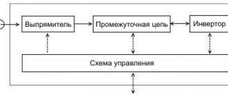
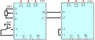
Scheme 1. Variable frequency drive.
A frequency converter (FC) is a device that combines a rectifier and an inverter. The rectifier converts alternating current of industrial frequency into direct current, and the inverter vice versa. Output thyristors (GTO) or transistors (IGBT), opening and closing by electronic control, generate the required voltage, similar to three-phase. The ability to change the voltage frequency allows you to change the power supplied to the load not discretely (as with mechanical adjustment), but continuously. Due to this principle of operation, a variable frequency drive can smoothly regulate the rotation parameters of the motor.
Advantages of using variable frequency drives for IM control
- Facilitates the starting mode of the drive.
- Allows the engine to run for a long time, regardless of the load level.
- Provides greater accuracy of adjustment operations.
- Allows you to monitor the status of individual nodes in the circuits of an industrial electrical network. Due to this, it is possible to keep a constant record of the amount of time the engines have worked in order to later evaluate their performance.
- The presence of electronic components makes it possible to diagnose engine malfunctions remotely.
- Various feedback sensors (pressure, temperature) can be connected to the device. As a result, the rotation speed will be stable under constantly changing loads.
- When the mains voltage fails, controlled braking and restart are activated.
- As a result:
- the level of efficiency increases due to which you can save about 30-35% of electricity;
- the quantity and quality of the final product increases;
- wear of component mechanisms is reduced;
- equipment service life increases.
According to the latest statistics, approximately 70% of all electricity generated in the world is consumed by electric drives. And every year this percentage is growing.
With a correctly selected method of controlling an electric motor, it is possible to obtain maximum efficiency, maximum torque on the shaft of the electric machine, and at the same time the overall performance of the mechanism will increase. Efficiently operating electric motors consume a minimum of electricity and provide maximum efficiency.
For electric motors powered by an inverter, the efficiency will largely depend on the chosen method of controlling the electrical machine. Only by understanding the merits of each method can engineers and drive system designers get the maximum performance from each control method.
For asynchronous electric motors connected to a frequency converter, the following main control methods exist:
1. Scalar
· Scalar U/f control;
· Scalar U/f control with encoder;
2. Vector
· Open-loop vector control;
· Closed loop vector control;
All four methods use PWM pulse width modulation, which changes the width of a fixed signal by varying the width of the pulses to create an analog signal.
SCALAR REGULATION
U/f control method
The scalar method of controlling an AC induction motor is to maintain a constant voltage/frequency (U/f) ratio throughout the entire operating speed range, while only controlling the magnitude and frequency of the supply voltage.
The U/f ratio is calculated based on the nominal values (voltage and frequency) of the controlled AC motor. By maintaining a constant value of the U/f ratio, we can maintain a relatively constant magnetic flux in the motor gap. If the U/f ratio increases then the motor becomes overexcited and vice versa if the ratio decreases the motor is in an unexcited state.
Dependence of motor supply frequency on time with scalar control
Changing the motor supply voltage with scalar control
At low speeds it is necessary to compensate for the voltage drop across the stator resistance, so the U/f ratio at low speeds is set higher than the nominal value. The scalar control method is most widely used to control asynchronous electric motors. It is often used in simple electric drive systems due to its simplicity and the minimum number of parameters required for operation. This control method does not require the mandatory installation of an encoder and mandatory settings for a variable-frequency electric drive. This leads to lower costs for auxiliary equipment (sensors, feedback wires, relays, etc.). U/f control is quite often used in high-frequency equipment, for example, it is often used in CNC machines to drive spindle rotation.
U/f is the only way to regulate the speed of an asynchronous electric motor, which allows the control of several electric drives from one frequency converter. Accordingly, all machines start and stop simultaneously and operate at the same frequency.
But this control method has several limitations. For example, when using the U/f control method without an encoder, there is absolutely no certainty that the shaft of an asynchronous machine rotates. In addition, the starting torque of an electric machine at a frequency of 3 Hz is limited to 150%. Yes, the limited torque is more than enough to accommodate most existing equipment. For example, almost all fans and pumps use the U/f control method.
This method is relatively simple due to its looser specification. Speed regulation is typically in the range of 2% - 3% of the maximum output frequency. The speed response is calculated for frequencies above 3 Hz. The response speed of the frequency converter is determined by the speed of its response to changes in the reference frequency. The higher the response speed, the faster the electric drive will respond to changes in the speed setting.
The speed control range when using the U/f method is 1:40. By multiplying this ratio by the maximum operating frequency of the electric drive, we obtain the value of the minimum frequency at which the electric machine can operate. For example, if the maximum frequency value is 60 Hz and the range is 1:40, then the minimum frequency value will be 1.5 Hz.
The U/f pattern determines the relationship between frequency and voltage during operation of a variable frequency drive. According to it, the rotation speed setting curve (motor frequency) will determine, in addition to the frequency value, also the voltage value supplied to the terminals of the electric machine.
Operators and technicians can select the desired U/f control pattern with one parameter in a modern frequency converter. Pre-installed templates are already optimized for specific applications. There are also opportunities to create your own templates that will be optimized for a specific variable frequency drive or electric motor system.
Devices such as fans or pumps have a load torque that depends on their rotation speed. The variable torque (picture above) of the U/f pattern prevents control errors and improves efficiency. This control model reduces magnetizing currents at low frequencies by reducing the voltage on the electrical machine.
Constant torque mechanisms such as conveyors, extruders and other equipment use a constant torque control method. With constant load, full magnetizing current is required at all speeds. Accordingly, the characteristic has a straight slope throughout the entire speed range.
f control method with encoder
With the scalar control method, the speed of an induction motor is controlled by setting the stator voltage and frequency, so that the magnetic field in the gap is maintained at the desired value. To maintain a constant magnetic field in the gap, the U/f ratio must be constant at different speeds.
As the speed increases, the stator supply voltage must also increase proportionally. However, the synchronous frequency of an induction motor is not equal to the shaft speed, and the slip of an asynchronous motor depends on the load. Thus, a scalar open-loop control system cannot accurately control speed when a load is present. To solve this problem, speed feedback, and therefore slip compensation, can be added to the system.
Thus, if it is necessary to increase the accuracy of rotation speed control, an encoder is added to the control system. The introduction of speed feedback using an encoder allows you to increase the control accuracy to 0.03%. The output voltage will still be determined by the specified U/f pattern.
This control method is not widely used, since the advantages it provides compared to standard U/f functions are minimal. Starting torque, response speed and speed control range are all identical to standard U/f. In addition, when operating frequencies increase, problems with the operation of the encoder may arise, since it has a limited number of revolutions.
When to use scalar control
Scalar control of AC motors is a good alternative for applications where there is no variable load and high dynamic loads (fans, pumps). Scalar control does not require a rotor position sensor to operate, and the rotor speed can be estimated from the frequency of the supply voltage. When scalar control is used, a high-performance digital signal processor is not required as is the case with vector control.
Disadvantages of Scalar Control
With scalar motor control, the stator currents are not directly controlled.
And the process of scalar regulation of a synchronous motor with permanent magnets can easily become uncontrollable (leave the synchronous state), especially when the load torque exceeds the value of the limiting torque of the electric drive. The scalar method is not suitable for controlling a synchronous motor at low speeds with high dynamic loads.
scalar control method is relatively simple to implement, but has several significant disadvantages:
· firstly, if a speed sensor is not installed, it is impossible to control the rotation speed of the shaft of an asynchronous motor, since it depends on the load (the presence of a speed sensor solves this problem), and in the case of a synchronous motor, when the load changes, you can completely lose control;
Secondly, you cannot control the moment. Of course, this problem can be solved using a torque sensor, but the cost of installing it is very high, and will most likely be higher than the electric drive itself. In this case, torque control will be very inertial;
· it is also impossible to control torque and speed at the same time.
Scalar control is sufficient for most tasks in which an electric drive is used with an engine speed control range of up to 1:10.
When maximum speed is required, the ability to regulate over a wide range of speeds and the ability to control the torque of the electric motor, vector control is used.
VECTOR CONTROL
Vector control is a method of controlling brushless AC motors, which allows you to independently and practically inertia-free control the rotation speed and torque on the motor shaft.
The main idea of vector control is to control not only the magnitude and frequency of the supply voltage, but also the phase. In other words, the magnitude and angle of the space vector are controlled. Vector control has higher performance compared to scalar control. Vector control eliminates almost all the disadvantages of scalar control.
Open-loop vector control
Open-loop vector control (VC) is used for broader and more dynamic speed control of an electrical machine. When starting from a frequency converter, electric motors can develop a starting torque of 200% of the rated torque at a frequency of only 0.3 Hz. This significantly expands the list of mechanisms where an asynchronous electric drive with vector control can be used. This method also allows you to control the machine's torque in all four quadrants.
The torque is limited by the motor. This is necessary to prevent damage to equipment, machinery or products. The torque value is divided into four different quadrants, depending on the direction of rotation of the electric machine (forward or reverse) and depending on whether the electric motor implements regenerative braking mode. Limits can be set for each quadrant individually, or the user can set the overall torque in the frequency converter.
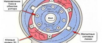
The motor mode of an asynchronous machine will be provided that the magnetic field of the rotor lags behind the magnetic field of the stator. If the rotor magnetic field begins to outstrip the stator magnetic field, then the machine will enter regenerative braking mode with energy release; in other words, the asynchronous motor will switch to generator mode.
For example, a bottle capping machine may use torque limiting in quadrant 1 (forward direction with positive torque) to prevent overtightening of a bottle cap. The mechanism moves forward and uses the positive torque to tighten the bottle cap. But a device such as an elevator with a counterweight heavier than the empty car will use quadrant 2 (reverse rotation and positive torque). If the cabin rises to the top floor, then the torque will be opposite to the speed. This is necessary to limit the lifting speed and prevent the counterweight from free falling, since it is heavier than the cabin.
Current feedback in these frequency converters allows you to set limits on the torque and current of the electric motor, since as the current increases, the torque also increases. The output voltage of the inverter may increase if the mechanism requires more torque, or decrease if its maximum permissible value is reached. This makes the vector control principle of an asynchronous machine more flexible and dynamic compared to the U/F principle.
Also, frequency converters with vector control and open loop have a faster speed response of 10 Hz, which makes it possible to use it in mechanisms with shock loads. For example, in rock crushers, the load is constantly changing and depends on the volume and dimensions of the rock being processed.
Unlike the U/F control pattern, vector control uses a vector algorithm to determine the maximum effective operating voltage of the electric motor.
Vector control of the VU solves this problem due to the presence of feedback on the motor current. As a rule, current feedback is generated by the internal current transformers of the frequency converter itself. Using the obtained current value, the frequency converter calculates the torque and flux of the electrical machine. The basic motor current vector is mathematically split into a magnetizing current and torque vector.
Using the data and parameters of the electrical machine, the inverter calculates the magnetizing current and torque vectors. To achieve maximum performance, the frequency converter must keep the vector data separated by an angle of 900. This is significant since sin 900 = 1, and a value of 1 represents the maximum torque value.
In general, vector control of an induction motor provides tighter control. The speed regulation is approximately ±0.2% of the maximum frequency, and the regulation range reaches 1:200, which can maintain torque when running at low speeds.
Vector feedback control
Feedback vector control uses the same control algorithm as open-loop VAC. The main difference is the presence of an encoder, which allows the variable frequency drive to develop 200% starting torque at 0 rpm. This point is simply necessary to create an initial moment when moving off elevators, cranes and other lifting machines, in order to prevent subsidence of the load.
The presence of a speed feedback sensor allows you to increase the system response time to more than 50 Hz, as well as expand the speed control range to 1:1500. Also, the presence of feedback allows you to control not the speed of the electric machine, but the torque. In some mechanisms, it is the torque value that is of great importance. For example, winding machine, clogging mechanisms and others. In such devices it is necessary to regulate the torque of the machine.
Advantages of vector control:
· high accuracy of speed control;
· smooth start and smooth rotation of the engine over the entire frequency range;
· quick response to load changes: when the load changes, there is practically no change in speed;
· increased control range and control accuracy;
· losses due to heating and magnetization are reduced, and the efficiency of the electric motor is increased.
The disadvantages of vector control include:
· the need to set the parameters of the electric motor;
· large speed fluctuations at constant load;
· high computational complexity.
Comparison table of frequency converter control methods.
| Control method | Speed control range | Speed error3,% | Torque rise time, ms | Starting torque | Price | Description | ||
| Scalar | 1:101 | 5-10 | Not available | Short | Very low | It has a slow response to load changes and a small speed control range, but is easy to implement. | ||
| Vector | Linear | Field-oriented control | >1:2002 | 0 | <1-2 | High | High | Allows you to smoothly and quickly control the main engine parameters - torque and speed. For this method to work, information about the rotor position is required. |
| Direct torque control with FDA | >1:2002 | 0 | <1-2 | High | High | A hybrid method developed to combine the advantages of https://engineering-solutions.ru/motorcontrol/vector/#foc and https://engineering-solutions.ru/motorcontrol/vector/#dtc. | ||
| Nonlinear | Direct torque control with switching table | >1:2002 | 0 | <1 | High | High | It has high dynamics and a simple circuit, but a characteristic feature of its operation is high current and torque ripples. | |
| Direct self-government | >1:2002 | 0 | <1-2 | High | High | It has an inverter switching frequency lower than other methods and is designed to reduce losses when controlling high-power electric motors. | ||
Bibliography:
1. Botan Electric. “How to choose the right frequency converter control method? https://elenergi.ru, 2016
2. Cristian Busca. "Open loop low speed control for PMSM in high dynamic application. - Aalborg, Denmark.": Aalborg universitet, 2010
3. Bial Akin, “Nishant Garg. Scalar (V/f) control of 3-phase induction motors. Application report. SPRABQ8.- Dallas, USA.": Texas Instruments
4. Articles https://engineering-solutions.ru
VFD Application Industries
The list of industries is extensive; it is more difficult to find an industry where emergency situations are not applied:
Oil production and refining
: pumping equipment, drive of air cooling units (ACU) and cooling towers, comprehensive automation of various technological lines.
Metallurgy
: drives of roller tables, conveyors, rolling mills, winding devices of drawing mills, pumps, fans.
Mechanical engineering
: drive of processing machines, pumps, conveyor lines, printing machines.
Mining and processing production
: crushers, mixers, conveyors, sand and pulp pumps.
Chemical industry
: pumps, mixers, granulators, extruders, centrifuges, smoke exhaust and fan drives, automated control systems.
Food industry
: granulators, extruders, mills, crushers, cutters, pulp presses, labeling machines, conveyors, production lines, pumps, fans.
Housing and communal services
: various pumping equipment, automated control systems.
Construction complex
: cranes, lifting mechanisms.
Transport
: ship drive, electric transport.
Advantages of the frequency regulation method
- The electric motor can be controlled at a considerable distance in a convenient location
- Soft start-up and reduced device maintenance costs
- Possibility to increase productivity by adjusting the speed according to the required production needs
- Increased efficiency of the frequency converter up to 97% of an asynchronous machine and up to 95% increases energy efficiency due to the control method of the electric motor used
- The static converter is used for variable torque (low torque, low speeds) with a reduced voltage at the connection terminals to the electric motor. Also, for use in the case of constant torque and power, in such a case, high efficiency is achieved through smooth speed control. Thanks to these capabilities, the system can be considered universal
- Mandatory speed control helps achieve process optimization
How to choose a frequency converter
Please note:
- Power and type of asynchronous electric motor.
- Range and accuracy of speed control.
- The need to accurately maintain torque and rotation speed on the motor shaft.
- Compliance of the device design with personal wishes.
TIP: if any of the parameters must meet special requirements, then it is better to choose not a potentially suitable variable frequency electric drive, but one that is of a higher class.
Types of frequency converters
There are several types of frequencies, which are currently the most common for production and use:
Electric machine (electric induction) converters: used in cases where the use of electronic frequency converters is impossible or impractical. Structurally, such devices are asynchronous motors with a wound rotor, which operate in generator-converter mode.
These devices are converters with scalar control. At the output of this device, a voltage of a given amplitude and frequency is created to maintain a certain magnetic flux in the stator windings. They are used in cases where it is not necessary to maintain the rotor rotation speed depending on the load (pumps, fans and other equipment).
Electronic converters: widely used in any operating conditions for various equipment. Such devices are vector, they automatically calculate the interaction of the magnetic fields of the stator and rotor and provide a constant value of the rotor speed regardless of the load.
Completed projects
NPO "Vint", Moscow. Thrusters for ship propulsion. Vessels equipped with them gain greater maneuverability when mooring, passing through narrow spaces, and trawling. The risk of ship collisions is significantly reduced. Unloading and loading times are reduced, saving time and money.
Stroybezopasnost LLC, Tikhoretsk. Equipment for tower crane drives. This solution simplifies control, makes it possible to finely regulate the speed over a wide range, and results in the absence of inrush currents.
JSC "Tagmet", Taganrog. Roller conveyors of a slot hardening furnace. They ensure accurate pipe catching in the loading zone and separation at the outlet and trouble-free operation of the equipment. The main economic effect of using frequency converters is improving product quality.
OJSC "Ulyanovsk Sugar Factory", r.p. Tsilna, Ulyanovsk region. Press drive 500 kW. It regulates the speed according to the load: as a result, the chips are supplied unevenly and there are no transfers, while maintaining the desired level of pressure in the shaft. The service life of equipment is increased, the number of emergency stops is reduced, and process maintenance is simplified.
MUP "Vodokanal", Novocheboksarsk. Automated operational dispatch control system (ASODU) for water supply in Novocheboksarsk. In addition to reducing direct energy costs, the accident rate has decreased and the quality of service has improved.
Construction of the power section
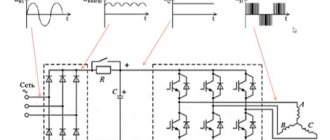
The most widely used are frequency converters with an intermediate DC link, built according to the rectifier-autonomous inverter circuit. The operating principle and scope of application of such frequency converters depend on the type of rectifier and autonomous inverter used (voltage inverter or current inverter).
There are several different rectifier designs. Based on their operating principle, they can be divided into three groups: controlled, semi-controlled and uncontrolled. Circuit design, all rectifiers are built using a three-phase bridge circuit.
The most widespread are uncontrolled rectifiers. Performed on the simplest and cheapest semiconductor devices - diodes, they are characterized by maximum simplicity and reliability, high efficiency, as well as a fairly high quality of the output (rectified) voltage and harmonic composition of the current consumed from the network. However, the uncontrollability of the energy conversion process does not allow the implementation of recovery modes, which are necessary in many cases.
Controlled rectifiers, usually made on low-frequency thyristors, lack both the disadvantages and most of the advantages of diode rectifiers. They have high efficiency and reversibility in the direction of energy conversion and are usually used in conjunction with autonomous current inverters to regulate the output current of the converter. The disadvantages of controlled rectifiers are the increased level of ripple of the rectified voltage, the reduced power factor, which decreases in proportion to the output voltage, and the one-way direction of the output current. If it is necessary to ensure the flow of rectified current in both directions, reversible thyristor converters are used, consisting of two thyristor rectifiers connected back-to-back, one of which is designed to flow the load current in the forward direction, and the other in the reverse direction. This complicates and increases the cost of the converter.
Semi-controlled rectifiers occupy an intermediate position between controlled and uncontrolled rectifiers, allowing you to regulate the value of the rectified voltage without the possibility of energy recovery into the network. In the case of controlled and semi-controlled rectifiers, it becomes possible to disconnect the power circuit of frequency converters from the network without the use of additional equipment.
Depending on the type of stand-alone inverter, the DC loop can be designed as a constant voltage link (usually a C or LC filter) or as a constant current link (a filter in the form of a reactor with significant inductance). The capacitance value of the capacitor in the DC link is usually 2000–20000 μF; Such capacitors are large in size and high in cost.
Characteristic features of autonomous current inverters (AIT, Fig. 1a) are power supply from a current source (a choke of significant inductance is included in the source circuit), exchange of reactive energy of the load with a switching capacitor, significant voltage fluctuation at the inverter input at a constant source current, as well as dependence of the form voltage curve at the output and input of the inverter depending on the nature of the load. AITs are technically simpler to implement than AINs, since they do not have a return diode bridge. In frequency converters based on AIT, when using controlled rectifiers, it is possible to recuperate energy into the network, which is important for electric drives operating in intermittent operating modes.
Rice. 1. a)
A characteristic disadvantage of AIT is that it cannot operate at idle speed (with the engine turned off). In addition, when using AIT, significant power losses and the formation of additional disturbing moments in the engine are possible, leading to speed fluctuations. If it is necessary to generate motor currents close to sinusoidal, a significant complication of the AIT circuit is required.
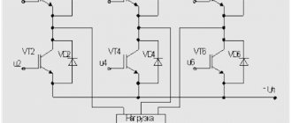
Features of autonomous voltage inverters (AVI, Fig. 1b) are power supply from a voltage source, closure of the reactive current circuit of the load through freewheeling diodes, and independence of the shape of the voltage curve at the inverter output from the nature of the load. The disadvantage of the AIS is the need to use reversible rectifiers to organize regenerative operating modes of the electric drive. However, the use of voltage inverters allows, without complicating the circuit, to obtain high energy performance and provide output currents close to sinusoidal. This is what determines the widespread use of AIN in modern electric drives.
Rice. 1. b)
To construct power switches in the range of switched currents up to 50 A, insulated gate bipolar transistors (IGBTs) and insulated gate field-effect transistors (MOSFETs), as well as low- and high-frequency diodes and thyristors are used. Power bipolar transistors in the range up to 50 A find their main application in low-cost industrial equipment. In the range of switched currents of more than 50 A, the main devices used are power modules based on bipolar transistors and turn-off thyristors (GTO, GCT, IGCT). Particular attention should be paid to transistor and diode-transistor modules made using integrated technology based on IGBT-type transistors. Low power losses in key modes, high operating voltages and currents, short turn-on and turn-off times of these modules, as well as the possibility of using them in parallel operation, make it possible to create powerful and compact converter units with a high switching frequency of semiconductor switches.
Rice. 2.
Technical features of using a frequency drive
- To ensure high performance, you can freely switch to any mode in the settings.
- Almost all devices have diagnostic functions, which allows you to quickly resolve the problem. However, it is recommended to first check the settings to eliminate the possibility of involuntary actions by employees.
- An adjustable drive can synchronize conveyor processes, or set a certain ratio of interdependent quantities. Reducing equipment leads to optimization of technology.
- In the auto-tuning state, the motor parameters are automatically stored in the memory of the frequency converter. This increases the accuracy of torque calculations and improves slip compensation.
Application area
Manufacturers offer a wide range of drives used in areas where electric motors are used. Ideal solution for all types of loads, including pumps and fans. Mid-range systems are used in coal-fired power plants, mining, mills, utilities, etc. The rating range is as follows: 3 kV, 3.3 kV, 4.16 kV, 6 kV, 6.6 kV, 10 kV and 11 kV.
With the advent of an adjustable electric drive, controlling water pressure does not cause problems for the end user. The interface with a well-thought-out script structure is ideal for controlling pumping equipment. Thanks to its compact design, the drive can be installed in a variety of cabinet designs. New generation products have the properties of advanced technology:
- high speed and accuracy of control in vector mode;
- significant energy savings;
- fast dynamic characteristics;
- large low-frequency torque;
- double braking, etc.
Purpose and technical indicators
Complete VFDs with voltages up to and above 1 kV (designed for receiving and converting energy, protecting electrical equipment from short-circuit currents, overloads) allow:
- smoothly start the engine, and, therefore, reduce its wear;
- stop, maintain engine speed.
Complete cabinet-mounted VFDs up to 1 kV perform the same tasks in relation to motors with a power of 0.55 - 800 kW. The drive operates normally when the mains voltage is between -15% and +10%. During non-stop operation, power reduction occurs if the voltage is 85%-65%. Overall power factor cosj = 0.99. The output voltage is automatically regulated by an automatic transfer switch (ATS).