Current to voltage converter
A current-to-voltage converter (or IU converter for short) is a circuit solution that allows you to convert the output current signal of a source into voltage.
It is also called an amplifier - resistance converter . This name was given in the technical literature because the simplest current-to-voltage converter is a resistor.
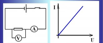
All the magic of transformation occurs according to Ohm's law. Current iin flowing through resistor R Uout to drop across it . The magnitude of this voltage is directly proportional to the product of the resistor resistance and the input current. Perhaps the formula sounds even simpler:
Uout = R × iin
The main disadvantage of using a single resistor is its non-zero resistance. This circumstance becomes a serious problem when the source is not able to provide the required voltage level across the resistor. The result will be a voltage drop at the output.
Resistance affects the operation of the converter even more if the current source has a small output operating range. Such sources include, for example, a photodiode. Its output current is units of μA.
In the case of a DAC , especially a high-quality one, using a resistor for conversion is preferable. Read why and why in the article Resistor for a DAC with current output. This is due to some phase problems of the circuits that will be discussed. Fortunately for us, sources like the photodiode do not care about phase distortion.
How does a transformer work?
The transformer operates by mutual induction. First, let's look at what induction is.
What is induction
If an electric current is passed through a wire, a magnetic field will appear.
The magnetic field is an integral part of the electric field. And in a magnetic field the energy of the electric one is conserved.
In permanent magnets, the presence of a magnetic field is explained by the direction of the “domains in one direction.” Those. Each individual atom has its own small magnetic field. With permanent magnets, these small magnetic fields point in one direction. This is why a permanent magnet has such a strong magnetic field.
And other materials can be magnetized, i.e. make sure that the magnetic fields are directed in one direction. This will result in an “artificially created” magnet.
By the way, a magnet that magnetizes and demagnetizes screwdrivers is very popular among repairmen. This type of screwdriver is convenient to use, since small bolts and screws will remain on the screwdriver and will not fall off in case of careless movement.
And inductance is the ability of a material to accumulate a magnetic field when an electric current flows through this material.
The more a material can create a magnetic field, the higher its inductance.
The magnetic field can be increased by making a coil.
All you have to do is take the wire and wrap it around the frame. And the magnetic fields of the turns will add up.
This is the inductor.
The wire in the inductor must be insulated. Because if at least one turn is in a short circuit with another, then the magnetic field will be uneven. There will be an interturn short circuit, due to which the magnetic field will lose its uniformity.
If we apply direct current to the coil, then the magnetic field will be constant. It won't change. What if you disconnect the coil from the source? Then the phenomenon of self-induction will occur. As the current decreases, there is nothing left to support the magnetic field. And all the energy that was in the magnetic field turns into electrical energy.
A change in the magnetic field creates an electric field.
Increase in inductance by core
How to increase inductance? Only using the number of turns and wire diameter? The inductance is also influenced by the environment. Air is not the best material for storing or transmitting a magnetic field. It has low magnetic permeability. Moreover, with changes in air density and temperature, this value changes. Therefore, ferromagnets are used to increase inductance. These include iron, nickel, cobalt, etc.
If you make a core in the center of the coil from such materials, you can increase the inductance of the coil many times over.
Cores (magnetic cores) are made from ferromagnets. They mainly use electrical steel, which is specially made for these purposes.
By the way, it is now much easier to regulate the inductance with the core. It is enough to smoothly move the core inside the coil, and the inductance will change smoothly. This is more convenient than moving the coils away from each other.
Mutual inductance and the principle of current transfer
Since energy can be stored in a coil due to a magnetic field, then this energy can be transferred to another coil.
Let's say there are two identical inductors. One is connected to power, the other is not.
When power is connected, a magnetic field will appear at the first coil. And if you bring the second coil closer to the first, an EMF is induced in the second coil due to the magnetic field of the first.
But the EMF of the second coil will not last long. If a constant voltage is applied to the first coil, then the magnetic field will be constant.
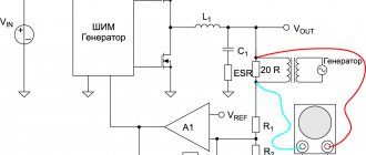
Circuit of current-voltage converter on op-amp
The current-to-voltage converter circuit is not new at all, but it is proven and trouble-free. In general it looks like this:
iin signal current flows into the inverting input. Since the input current of an ideal op-amp is zero, all incoming current goes to the feedback R. This current creates a voltage drop across the resistor according to the same Ohm’s law.
As a result, the op-amp will try to maintain a voltage across the load resistance RN that is proportional to the input current. The gain of the circuit in this case has the dimension of resistance. Which once again explains the Soviet name amplifier-resistance converter:
K = Uout ÷ iin = R
Need for voltage conversion
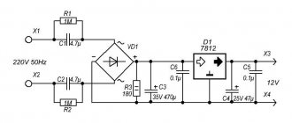
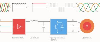
Each device has requirements for the characteristics of the supply current. In everyday life, alternating current with a frequency of 50 Hz is usually used, from which the one needed for a particular type of electrical equipment is obtained. For example, a power adapter for a smartphone can be used for this purpose.
Sometimes it becomes necessary to perform the opposite transformation. This is true in cases where electricity is received in the form of direct current. This situation occurs, for example, when using solar panels. This method is cheap and effective, but requires further conversion of DC to AC.
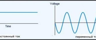
Converting DC to AC is beneficial due to the advantages of the latter. The following facts can be cited as an example:
- Use in transformers reduces losses when transmitting electricity over significant distances.
- Alternating current ensures efficient operation of induction heaters.
- Choke filters make it possible to get rid of high-frequency interference. The frequency is selected by changing the inductance of the coil.
- The use of alternating current allows you to obtain a constantly changing magnetic field.
Converter for grounded source
Let's consider several circuits of a current-to-voltage converter using an op-amp, suitable for any case. Let's start with the converter circuit for the photodiode.
The direction of current flow is shown by an arrow, and for this case the output voltage will be:
Uout = − iin × R
The minus sign appears due to the selected direction of photodiode current flow. (Indicated by the arrow in the diagram above)
This diagram also shows an additional 1 MΩ resistor from the non-inverting ( + ) input of the op-amp to ground. The circuit will remain operational without this resistor, and the input of the operational amplifier in this case is directly grounded.
However, with a 1 MΩ resistor in the feedback circuit, for every 1 µA of input current, 1 Volt of voltage will be generated at the output. At this gain (a million times) a resistor is desirable due to the non-ideal nature of op amps.
The current-to-voltage converter is also used with signal sources connected to the power bus. This circuit is often used with elements such as phototransistors. The phototransistor consumes (passes) current under the influence of an external light source, the positive power bus.
Areas of use
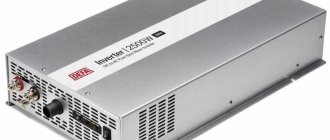
100 ampere separator
The scope of application of multi-zone voltage converters is very extensive. They are traditionally used for the following purposes:
- in linear devices for distribution and transmission of electricity;
- for carrying out such critical technological operations as welding, heat treatment and the like;
- when it is necessary to supply power to load circuits in a wide variety of technical fields.
In the first case, the EMF generated at power plants is increased with the help of these devices from 6-24 kV to 110-220 kV - in this form it is easier to “drive” it through wires over long distances. At regional substations, other transformer devices ensure its reduction, first to 10 (6.3) kV, and then to the usual 380 Volts.
When servicing process equipment, voltage converters are used as electrothermal installations or welding transformers.
In industry
The most extensive area of application is providing high-quality power to the following industrial designs of consumers:
- equipment operating in automatic control and monitoring lines;
- telecommunications and communication devices;
- a wide range of electrical measuring instruments;
- special radio and television equipment and the like.
A special function is performed by so-called “isolating” transformers, used to isolate load lines from the high-voltage input.
Since such converters “play an auxiliary role,” most often they have low power and relatively small dimensions.
In everyday life, medicine and defense industry
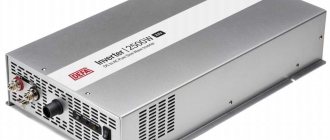
Voltage converter 24/12V DC-20
Voltage converters are widely used in everyday life. Most power supplies used for charging household appliances, as well as more complex devices such as:
- Surge Protectors;
- inverters;
- backup power supplies, etc.
These devices are most in demand in medicine, the military, as well as in energy and science. In these industries, they are subject to particularly “strict” requirements regarding the quality of the converted voltage (“purity” of the sinusoid, for example).
Current to voltage converter for ungrounded source
Such a converter is distinguished by the presence of a second current-sensing resistor in the signal current circuit, which is grounded. The circuit of a symmetrical current-voltage converter is similar to a differential amplifier.
As a result of the voltage drop across the grounded resistor, the op-amp input potential drops below the ground potential, and the output voltage is set to:
Uout = −2 × iin × R
A symmetrical current-to-voltage converter is an example of an operating circuit that requires an ungrounded (floating) signal source. The same photodiode can serve as such a source. In this case, the photodiode can be moved outside the board. To further minimize interference, it is advisable to use a shielded cable with the shield connected to ground.
Types of inverters
Inverters can be classified according to several criteria. One of them is the shape of the received signal. Inverters are capable of producing:
- Square wave signals.
- Stepped shape. In this case, the DC voltage is processed in two stages. First, unipolar pulses of the desired type and double frequency are formed. Then, using a bridge converter, a multipolar signal with the necessary characteristics is obtained.
- Sinusoidal shape. In this case, a high-frequency signal of the same amplitude is first obtained. Special modulation is then performed repeatedly using a bridge inverter.
Based on their operating principle, inverters are divided into autonomous and grid-driven. The latter are called dependent. They are used, for example, on electric locomotives as power converters.
Autonomous devices are divided into:
- voltage inverters;
- current;
- resonant.
Inverters are built based on different circuits:
- A bridge inverter without a transformer is used to convert DC voltage in cases where it is necessary to obtain output power above 500 VA at a voltage of 220 or 380 V.
- A zero-output transformer circuit converts DC to AC when no more than 250-500 VA is required. Such an inverter will provide power to devices that consume 12 or 24 V.
- For industrial purposes, when power from several kilovolt-amperes to tens is required or to provide energy for critical equipment, a bridge inverter with a transformer is used.
In all of these cases, an alternating current is obtained, the amplitude of which in shape to one degree or another approaches a sinusoid.
Questions about the transformer design
-Why is the gap between the coils kept to a minimum? This is done for better contact of magnetic fields. If the gap is large, then the efficiency of the transformer will be low.
-Is it possible to make a transformer without a core with the same power as one with a core? Yes, but then you will have to increase the number of turns to increase the magnetic flux. For example, with a core, the windings can have several thousand turns. And without a core, you will have to increase the magnetic flux due to turns. And the number of turns will be several tens of thousands. This not only increases the size of the coils, but also reduces their efficiency and increases the chances of overheating.
-Is it possible to connect a step-down transformer as a step-up transformer? If you have a transformer that lowers the mains voltage from 220 V to 12 V, then it can be connected as a step-up one. That is, you can apply an alternating voltage of 12 V to the secondary winding and get an increased voltage of 220 V on the primary.
-What will happen if mains voltage is applied to the secondary winding of the step-down transformer? Then the winding will burn out. Its resistance, number of turns and wire cross-section are not designed for such voltages.
-Is it possible to make a transformer yourself with your own hands at home? Yes, this is quite possible. And many radio amateurs and electronics engineers do this. And some also earn money. selling finished products. But it is worth remembering that this is long, complex and not easy work. We need quality materials. This includes transformer iron, enameled copper wires of various sections, and insulating materials.
All materials must be of high quality. If the copper wire is poorly insulated, then an interturn short circuit is possible, which will inevitably lead to overheating. First you need to calculate all the parameters of the future transformer. This can be done using various programs that are available online.
Next, there are long hours of assembly. Especially if you decide to wind a toroidal transformer.
You need to wind the turns tightly and evenly, write down every ten so as not to get confused and not change the characteristics of the future converter or power supply.
-What happens if you turn on a transformer without a core? Since the transformer was initially designed with a core, it will not be able to completely convert the voltage. That is, there will be something on the secondary, but obviously not the same parameters. And if you connect a load to windings without a core, they will quickly heat up and burn out.
Transformer faults
The main malfunctions of transformers include:
- Corrosion and rust on the core;
- Overheating and insulation failure;
- Interturn short circuit;
- Deformation of the housing, windings and core
- Water getting into the winding.
How to check for integrity
The transformer can be checked with a conventional multimeter. Set the device to resistance measurement mode and check the windings.
They shouldn't be on edge, ever. If there are no breaks anywhere, then you can find the primary and secondary windings by measuring resistance. The primary winding of a step-down transformer will have a higher resistance than the secondary winding. This is all due to the number of turns. The more turns and the smaller the diameter of the wire, the greater the winding resistance.
You can also find a passport for your transformer. It indicates the resistance of the windings and their parameters, which will need to be checked with a multimeter.
Safely test transformer operation
If you decide to wind your transformer or test the old one, then be sure to connect the light bulb to the open circuit (in series!). If something wrong happens, the light bulb will light up and take over the current and be able to save the faulty transformer.
Transformers are used in many places. Their design is different and for each task it is unique in its own way.
useful links
- Working with ADC (ADC) in ESP32 in documentation from Espressif (ENG).
- Working with ADC (ADC) in ESP32 in documentation from NodeMCU (ENG).
- Recommendations for ESP32 circuit design from the manufacturer. Pay attention to VDDA - analog power supply - reference voltage for the ADC.
- An example of working with an ESP32 (ENG) ADC.
- Working with ADC in ESP8266 (Eng).
- ADC in ESP8266 (Eng).
- Discussion of what is the maximum voltage for the ESP8266 (ENG) ADC.
- Discussion of how to use the ESP8266 (RUS) ADC.
- Discussion of ESP32 ADC accuracy (ENG).
Spread the love