Design features and operating principle
Of the several methods of converting voltage to power electronic components, two that are most widespread can be identified:
- Analog, the main element of which is a step-down transformer, in addition to its main function, it also provides galvanic isolation.
- Impulse principle.
Let's look at how these two options differ.
PSU based on a power transformer
Let's consider a simplified block diagram of this device. As can be seen from the figure, a step-down transformer is installed at the input, with its help the amplitude of the supply voltage is converted, for example, from 220 V we get 15 V. The next block is a rectifier, its task is to convert the sinusoidal current into a pulsed one (the harmonic is shown above the symbolic image). For this purpose, rectifying semiconductor elements (diodes) connected via a bridge circuit are used. Their operating principle can be found on our website.
Simplified block diagram of an analog power supply
The next block performs two functions: it smoothes the voltage (a capacitor of appropriate capacity is used for this purpose) and stabilizes it. The latter is necessary so that the voltage does not “drop” when the load increases.
The given block diagram is greatly simplified; as a rule, a source of this type has an input filter and protective circuits, but this is not important for explaining the operation of the device.
All the disadvantages of the above option are directly or indirectly related to the main design element - the transformer. Firstly, its weight and dimensions limit miniaturization. In order not to be unfounded, we will use as an example a step-down transformer 220/12 V with a rated power of 250 W. The weight of such a unit is about 4 kilograms, dimensions 125x124x89 mm. You can imagine how much a laptop charger based on it would weigh.
Step-down transformer OSO-0.25 220/12
Secondly, the price of such devices is sometimes many times higher than the total cost of the other components.
Pulse devices
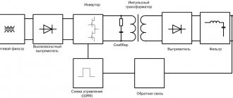
As can be seen from the block diagram shown in Figure 3, the operating principle of these devices differs significantly from analog converters, primarily in the absence of an input step-down transformer.
Figure 3. Block diagram of a switching power supply
Let's consider the operating algorithm of such a source:
- Power is supplied to the network filter; its task is to minimize network noise, both incoming and outgoing, that arises as a result of operation.
- Next, the unit for converting sinusoidal voltage into pulsed constant voltage and a smoothing filter come into operation.
- At the next stage, an inverter is connected to the process; its task is related to the formation of rectangular high-frequency signals. Feedback to the inverter is carried out through the control unit.
- The next block is IT, it is necessary for automatic generator mode, supplying voltage to the circuit, protection, controller control, as well as the load. In addition, the IT task includes ensuring galvanic isolation between high and low voltage circuits.
Unlike a step-down transformer, the core of this device is made of ferrimagnetic materials, this contributes to the reliable transmission of RF signals, which can be in the range of 20-100 kHz. A characteristic feature of IT is that when connecting it, the inclusion of the beginning and end of the windings is critical. The small dimensions of this device make it possible to produce miniature devices; an example is the electronic harness (ballast) of an LED or energy-saving lamp.
An example of miniature switching power supplies
- Next, the output rectifier comes into operation, since it works with high-frequency voltage; the process requires high-speed semiconductor elements, so Schottky diodes are used for this purpose.
- At the final phase, smoothing is performed on an advantageous filter, after which voltage is applied to the load.
Now, as promised, let’s look at the operating principle of the main element of this device – the inverter.
Simple power supply
Often there is a need to power several microcircuits or transistors. In this case, you can make a low-power power supply.
Good options are 78L05, 78L12, 79L05, 79L08 stabilizers.
These designs are designed for a current of one hundred milliamps, although they are very miniature and compact. Their installation on the radiator is not required.
- Making your own power supply is easy. The voltage is supplied through a stabilizer.
- In this scheme, the stabilizer is a limiter on the flow of elements.
- The allowed value is one ampere, so the remaining elements of the block must be designed for a current of more than one ampere.
- That is, after equalization, the stabilizer input needs to be supplied a few volts more than the output for smooth operation.
- Do not overestimate the U value to prevent overheating of the microcircuit.
How does an inverter work?
RF modulation can be done in three ways:
- pulse-frequency;
- phase-pulse;
- pulse width.
In practice, the last option is used. This is due both to the simplicity of implementation and to the fact that PWM has a constant communication frequency, unlike the other two modulation methods. A block diagram describing the operation of the controller is shown below.
Block diagram of a PWM controller and oscillograms of the main signals
The operating algorithm of the device is as follows:
The reference frequency generator generates a series of rectangular signals, the frequency of which corresponds to the reference one. Based on this signal, a sawtooth UP is formed, which is supplied to the input of the PWM comparator. The signal UUS coming from the control amplifier is supplied to the second input of this device. The signal generated by this amplifier corresponds to the proportional difference between UП (reference voltage) and UРС (control signal from the feedback circuit). That is, the control signal UUS is, in fact, a mismatch voltage with a level that depends on both the current across the load and the voltage across it (UOUT).
This implementation method allows you to organize a closed circuit that allows you to control the output voltage, that is, in fact, we are talking about a linear-discrete functional unit. Pulses are generated at its output, with a duration depending on the difference between the reference and control signals. Based on it, a voltage is created to control the key transistor of the inverter.
The process of stabilizing the output voltage is carried out by monitoring its level; when it changes, the voltage of the control signal UPC changes proportionally, which leads to an increase or decrease in the duration between pulses.
As a result, the power of the secondary circuits changes, which ensures stabilization of the output voltage.
To ensure safety, galvanic isolation between the power supply and feedback is necessary. As a rule, optocouplers are used for this purpose.
Can I use a planar transformer?
Of course you can. But the question is whether it is necessary. A planar transformer is a device based on a printed circuit board. The use of such models is indispensable for compact equipment such as phones, computers and others.
However, if we are talking about replacing or independently designing a device, then such an innovative technology is not needed due to the high cost and complexity of installation.
There is no need to reinvent the wheel: there are a number of methods for calculating, creating and installing traditional transformers that are ready to perform almost any task for the user. The use of a planar transformer is justified only if the device requires special compactness and mobility.
Strengths and weaknesses of pulsed sources
If we compare analog and pulse devices of the same power, the latter will have the following advantages:
- Small size and weight due to the absence of a low-frequency step-down transformer and control elements that require heat removal using large radiators. Thanks to the use of high-frequency signal conversion technology, it is possible to reduce the capacitance of the capacitors used in the filters, which allows the installation of smaller elements.
- Higher efficiency, since the main losses are caused only by transient processes, while in analog circuits a lot of energy is constantly lost during electromagnetic conversion. The result speaks for itself, increasing efficiency to 95-98%.
- Lower cost due to the use of less powerful semiconductor elements.
- Wider input voltage range. This type of equipment is not demanding in terms of frequency and amplitude; therefore, connection to networks of various standards is allowed.
- Availability of reliable protection against short circuits, overload and other emergency situations.
The disadvantages of pulse technology include:
The presence of RF interference is a consequence of the operation of the high-frequency converter. This factor requires the installation of a filter that suppresses interference. Unfortunately, its operation is not always effective, which imposes some restrictions on the use of devices of this type in high-precision equipment.
Special requirements for the load, it should not be reduced or increased. As soon as the current level exceeds the upper or lower threshold, the output voltage characteristics will begin to differ significantly from the standard ones. As a rule, manufacturers (even recently Chinese ones) provide for such situations and install appropriate protection in their products.
Accessories
To assemble a 12 Volt power supply circuit we will need:
- Thermistor;
- Capacitors (2 pcs.);
- Diode bridge;
- Drivers;
- Transformer;
- Diodes for output;
- Field effect transistors;
Scope of application
Almost all modern electronics are powered from blocks of this type, as an example:
- various types of chargers;
Chargers and external power supplies - external power supplies;
- electronic ballast for lighting fixtures;
- Power supply for monitors, TVs and other electronic equipment.
Monitor Switching Power Module
Assembling a switching power supply with your own hands
Let's consider the circuit of a simple power supply, where the above-described principle of operation is applied.
Schematic diagram of a pulse power supply
Designations:
- Resistors: R1 – 100 Ohm, R2 – from 150 kOhm to 300 kOhm (selectable), R3 – 1 kOhm.
- Capacitances: C1 and C2 - 0.01 µF x 630 V, C3 -22 µF x 450 V, C4 - 0.22 µF x 400 V, C5 - 6800 -15000 pF (selectable), 012 µF, C6 - 10 µF x 50 V, C7 – 220 µF x 25 V, C8 – 22 µF x 25 V.
- Diodes: VD1-4 - KD258V, VD5 and VD7 - KD510A, VD6 - KS156A, VD8-11 - KD258A.
- Transistor VT1 – KT872A.
- Voltage stabilizer D1 - microcircuit KR142 with index EH5 - EH8 (depending on the required output voltage).
- Transformer T1 - a w-shaped ferrite core with dimensions 5x5 is used. The primary winding is wound with 600 turns of wire Ø 0.1 mm, the secondary (pins 3-4) contains 44 turns Ø 0.25 mm, and the last winding contains 5 turns Ø 0.1 mm.
- Fuse FU1 – 0.25A.
The setup comes down to selecting the values of R2 and C5, which ensure excitation of the generator at an input voltage of 185-240 V.
Possible schematic solutions
There are two connection diagrams for the secondary winding of transformers, and indeed all electronics:
- A star that is used to increase the power of the network.
- A triangle that maintains constant voltage in the network.
Regardless of the chosen scheme, the most difficult is the manufacture and connection of small transformers. This includes atx, which is so popular in search engine queries. This is a model that is installed in computer system units, and it is extremely difficult to make it yourself.
Difficulties in the manufacture of small transformers include the complexity of the winding and insulation, the correct connection of the secondary winding, regardless of the chosen circuit, as well as the difficulty of finding a core. In short, it is easier and cheaper to buy such a transformer. But how to choose the right model is a completely different story.