Any electrical equipment is designed with stable mains voltage parameters in mind. This is necessary for two reasons:
- A device connected to the network must provide stable output current parameters in accordance with its intended purpose;
- The electrical circuit of the equipment needs protection from input current anomalies, which are the main cause of malfunctions and failure of electricity consumers due to burnout of their conductive contacts and elements.
To ensure that the mains supply voltage remains unchanged, a special device is used - a voltage stabilizer. It equalizes the characteristics of the input current and ensures that consumers are disconnected in the event of a short circuit or other critical network anomalies.
Parametric stabilizer
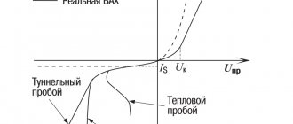
Its operating principle is based on the properties of semiconductor devices. The current-voltage characteristic of a semiconductor - a zener diode is shown in the graph.
During turn-on, the zener diode's properties are similar to those of a simple silicon-based diode. If the zener diode is turned on in the opposite direction, the electric current will initially increase slowly, but when a certain voltage value is reached, breakdown occurs. This is a mode where a small voltage increase creates a large zener diode current. The breakdown voltage is called stabilization voltage. To avoid failure of the zener diode, the current flow is limited by resistance. When the zener diode current fluctuates from the lowest to the highest value, the voltage does not change.
The diagram shows a voltage divider, which consists of a ballast resistor and a zener diode. A load is connected in parallel to it. When the supply voltage changes, the resistor current also changes. The zener diode takes over the changes: the current changes, but the voltage remains constant. When you change the load resistor, the current will change, but the voltage will remain constant.
Connection diagram
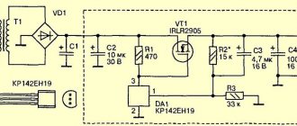
And here is the connection diagram for such stabilizers. This circuit is suitable for all stabilizers of the 78XX family.
In the diagram we see two capacitors that are sealed on each side. These are the minimum values of capacitors; it is possible, and even desirable, to supply a higher value. This is required to reduce ripple at both the input and output. For those who have forgotten what ripple is, you can look at the article on how to obtain a constant voltage from an alternating voltage.
Compensation stabilizer
The device discussed earlier is very simple in design, but makes it possible to connect power to the device with a current that does not exceed the maximum current of the zener diode. As a result, voltage stabilizing devices are used, which are called compensation devices. They consist of two types: parallel and serial.
The device is named according to the method of connection to the adjustment element. Compensating stabilizers of the sequential type are usually used. His diagram:
The control element is a transistor connected in series with the load. The output voltage is equal to the difference between the values of the zener diode and the emitter, which is several fractions of a volt, therefore it is considered that the output voltage is equal to the stabilizing voltage.
The considered devices of both types have disadvantages: it is impossible to obtain the exact value of the output voltage and make adjustments during operation. If it is necessary to create the possibility of regulation, then a compensatory type stabilizer is manufactured according to the following scheme:
In this device, regulation is carried out by a transistor. The main voltage is supplied by a zener diode. If the output voltage increases, the base of the transistor becomes negative in contrast to the emitter, the transistor will open by a larger amount and the current will increase. As a result, the negative voltage at the collector will become lower, as well as at the transistor. The second transistor will close, its resistance will increase, and the terminal voltage will increase. This leads to a decrease in the output voltage and a return to its previous value.
When the output voltage decreases, similar processes occur. You can adjust the exact output voltage using a tuning resistor.
Voltage stabilizer using a transistor
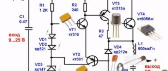
If you need to provide a more or less significant load current and reduce its effect on stability, you need to enhance the output current of the stabilizer using a transistor connected according to the emitter follower circuit (Fig. 2).
Rice. 2. Circuit of a parametric voltage stabilizer using one transistor.
The maximum load current of this stabilizer is determined by the formula:
In = (Ist – Ist.min)*h21e.
where Ist. – average stabilization current of the zener diode used, h21e – current transfer coefficient of the base of transistor VT1.
For example, if we use a KS212Zh zener diode (average stabilization current = (0.013-0.0001)/2 = 0.00645A), a KT815A transistor with h21 e - 40), we can get no more current from the stabilizer according to the circuit in Fig. 2: ( 0.006645-0.0001)40 = 0.254 A.
In addition, when calculating the output voltage, you need to take into account that it will be 0.65V lower than the stabilization voltage of the zener diode, because the silicon transistor drops about 0.6-0.7V (approximately take 0.65V).
Let's try to calculate the stabilizer according to the diagram in Figure 2.
Let's take the following initial data:
- Input voltage Uin = 15V,
- output voltage Uout = 12V,
- maximum current through the load In = 0.5A.
The question arises, what to choose - a zener diode with a large average current or a transistor with a large h21e?
If we have a KT815A transistor with h21e = 40, then, following the formula In = (Ist -Ist.min)h21e, we will need a zener diode with a difference between the average current and the minimum current of 0.0125A. In terms of voltage, it should be 0.65V greater than the output voltage, that is, 12.65V. Let's try to find it from the reference book.
Here, for example, is a KS512A zener diode, its stabilization voltage is 12V, the minimum current is 1 mA, the maximum current is 67 mA. That is, the average current is 0.033A. In general it is suitable, but the output voltage will not be 12V, but 11.35V.
We need 12V. It remains to either look for a 12.65V zener diode, or compensate for the lack of voltage with a silicon diode, connecting it in series with the zener diode as shown in Figure 3.
Fig.3. Schematic diagram of a parametric voltage stabilizer, supplemented with a diode.
Stabilizers on microcircuits
Such devices in the integrated version have increased characteristics of parameters and properties that differ from similar semiconductor devices. They also have increased reliability, small dimensions and weight, as well as low cost.
Series regulator
- 1 – voltage source;
- 2 – Adjustment element;
- 3 – amplifier;
- 4 – main voltage source;
- 5 – output voltage detector;
- 6 – load resistance.
The adjustment element acts as a variable resistance connected in series with the load. When the voltage fluctuates, the resistance of the adjustment element changes so that compensation for such fluctuations occurs. The control element is influenced by feedback, which contains a control element, a main voltage source and a voltage meter. This meter is a potentiometer from which part of the output voltage comes.
The feedback adjusts the output voltage used for the load, the output voltage of the potentiometer becomes equal to the main voltage. Voltage fluctuations from the main one creates some voltage drop at the regulation. As a result, the output voltage can be adjusted within certain limits by the measuring element. If the stabilizer is planned to be manufactured for a certain voltage value, then the measuring element is created inside the microcircuit with temperature compensation. If there is a large output voltage range, the measuring element is performed behind the microcircuit.
Parallel stabilizer
- 1 – voltage source;
- 2 – regulating element;
- 3 – amplifier;
- 4 – main voltage source;
- 5 – measuring element;
- 6 – load resistance.
If we compare the circuits of stabilizers, then a device of a sequential type has increased efficiency at partial load. A parallel type device consumes constant power from the source and supplies it to the control element and the load. Parallel stabilizers are recommended for use with constant loads at full load. The parallel stabilizer does not create a danger in the event of a short circuit, the sequential type does not create a danger during idle. At a constant load, both devices create high efficiency.
Principles for calculating characteristics
Parametric voltage stabilizer
For the simplest calculation of characteristics, the following data is required:
- Supply voltage;
- Load current;
- Output voltage.
Calculation procedure:
- Based on the output parameters, the type of stabilizing element is determined;
- The key element is selected according to the following criteria:
- Stabilization coefficient Вst≥In/Ist;
- The permissible collector-emitter voltage is greater than the maximum input voltage;
- The maximum collector current must be greater than the load.
Stabilizer on a chip with 3 pins
Innovative variants of sequential stabilizer circuits are made on a 3-pin microcircuit. Due to the fact that there are only three outputs, they are easier to use in practical applications, since they displace other types of stabilizers in the range of 0.1-3 amperes.
- Uin – raw input voltage;
- U out – output voltage.
You may not use containers C1 and C2, but they allow you to optimize the properties of the stabilizer. Capacity C1 is used to create system stability, capacitance C2 is needed for the reason that a sudden increase in load cannot be tracked by the stabilizer. In this case, the current is supported by capacitance C2. In practice, 7900 series microcircuits from Motorola are often used, which stabilize a positive voltage value, and 7900 – a value with a minus sign.
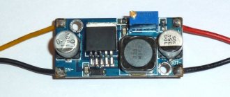
The microcircuit looks like:
To increase reliability and create cooling, the stabilizer is mounted on a radiator.
How to make a power supply for 5, 9.12 Volts
How to make a simple and highly stable power supply for 5, 9 or even 12 Volts? Yes, very simple. To do this, you need to read this article and install a stabilizer on the radiator at the output! That's all! The circuit will be approximately like this for a 5 Volt power supply:
Two electrolytic capacitors to eliminate ripple and a highly stable 5 volt power supply at your service! To get a power supply for a higher voltage, we also need to get a higher voltage at the output of the transformer. Aim for the voltage on capacitor C1 to be no less than in the datasheet for the stabilizer being described.
To ensure that the voltage stabilizer does not overheat, apply the minimum voltage specified in the datasheet to the input. For example, for the 7805 stabilizer this voltage is 7.5 Volts, and for the 7812 stabilizer the desired input voltage can be considered a voltage of 14.5 Volts. This is due to the fact that the voltage difference, and therefore the power, the stabilizer will dissipate on itself.
As you remember, the power formula is P=IU, where U is voltage and I is current. Consequently, the higher the input voltage of the stabilizer, the greater the power consumed by it. And excess power means heating. As a result of heating, such a stabilizer may overheat and enter a protection state, in which further operation of the stabilizer stops or even burn out.
Basic parameters of the zener diode
Let's consider the main parameters of the zener diode
according to its current-voltage characteristic.
Volt-ampere characteristics of the zener diode
Stabilization voltage Ust
determined by the voltage on the zener diode when
the stabilization current Ist
. Currently, zener diodes are produced with stabilization voltages from 0.7 to 200 V.
Maximum permissible direct stabilization current Ist.max
limited by the value of
the maximum permissible power dissipation Pmax
, which in turn depends on the ambient temperature.
Minimum stabilization current Ist.min
is determined by the minimum value of the current through the zener diode, at which the operability of the device is still fully maintained. Between the values of Ist.max and Ist.min, the volt-ampere characteristic of the zener diode is most linear and the stabilization voltage changes slightly.
Differential resistance of the zener diode rCT
– a value determined by the ratio of the increase in stabilization voltage on the device ΔUCT to the small increase in stabilization current ΔiCT that caused it.
A zener diode connected in the forward direction, like a conventional diode, is characterized by values of constant forward voltage Upr
and
the maximum permissible direct direct current Ipr.max
.
Transistor and Zener diode circuit
Connecting a key element to a simple zener diode device allows you to increase the load current with minimal difficulty. The use of a field-effect transistor instead of a bipolar one makes it possible to reduce power dissipation and reduce the drop at semiconductor junctions, thus increasing the efficiency of the design.
Important! When using FETs, the hand and tool must be grounded.
Which voltage stabilizer to choose depends on the requirements for the load current value, stabilization coefficient, and design dimensions.
This largely depends on personal preference. Compensation and parametric devices are easy to understand, easy to assemble and configure. Pulse devices are more technically complex. Although there are many off-the-shelf switching regulator ICs available, lack of a clear understanding of their operation can make troubleshooting difficult. A design selected with a certain current reserve can stand under load for an unlimited time.