Connecting a bathroom hood fan can be done in several ways.
- via door or motion sensor
- humidity sensor
- directly from a light bulb or lamp in the bathroom
But the most correct way to do this would be through a light switch installed on the bathroom lighting, or through a separate two-key switch.
How not to connect and why
The first options have a lot of inconveniences, which are not entirely noticeable at first.
For example, let’s say you set up the hood to turn on using a door opening sensor. At the same time, it turns off according to a timer after 5 minutes. It would seem very convenient.
However, it is quite problematic to install such a sensor on an interior door. Not to mention other aspects of operation. For example, what to do if you stay in the toilet longer than the set time.
Open and close the door again? What if there are guests in the kitchen?
In addition, the cables will have to be routed under the tiles, several extra holes will have to be drilled, etc. Simple motion sensors are sensitive to humidity and fail very quickly.
You will have to select expensive models with appropriate IP humidity protection, depending on the zones in the bathroom.
Some people consider the most convenient option to be installing a switch on the hood directly inside the bathroom. However, the PUE prohibits this.
Why this is so, the relevant links and explanations from Rostechnadzor specialists will be given at the end of the article.
https://youtu.be/https://youtu.be/wdpTUvxVWFU
_
Connecting a bathroom fan via a switch
Therefore, let's consider the most correct and reliable method - connecting from a lighting switch located on the outside of the bathroom.
For installation you will need very few materials:
- cable VVGnG-Ls 3*1.5mm2 or NYM 3*1.5mm2
Which one is better to choose, read the article “The best cable for wiring NYM or VVGnG-Ls”.
The body of most hoods is plastic, so these models do not need to be grounded. If you have ventilation with metal elements, then you will need a 4-core cable 4 * 1.5 mm2
- Vago terminal blocks
The loads here are small, so these terminals, controversial for many, would be quite appropriate here. There is no need for any twisting followed by welding, soldering or crimping.
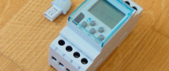
- the exhaust fan itself with a timer
Varieties and characteristics
The ERA model is the most popular in our market. Let's look at it in more detail.
Other mechanisms and models with a timer from Vents, Ballu, Electrolux are connected in a similar way.
Here are the technical specifications and detailed data for all popular models:
Electrolux EAFM-100THERA SB D100 OptimaVents 100 KDomovent 100 CERA D 100 E 100SCBallu Green EnergyERA D 100 4C ETVents 100 Quiet
Operating modes of the hood in the bathroom
These fans with a timer have two operating modes:
- toilet - upper position of a special jumper
- bathroom - lower position of the jumper
Switching modes is done on the control board in the upper right corner.
Others have similar jumpers class=”aligncenter” width=”720″ height=”420″[/img]
When working in the “toilet” mode, after turning on the light and supplying power to the board, the ventilation immediately starts working. As soon as the light is turned off, the fan does not stop, but will continue to spin for a certain time.
You set this time yourself by unscrewing the adjusting screw with a screwdriver.
In the “bathroom” mode, the operation is somewhat different. This mode is suitable specifically for showers and bathrooms, without a toilet.
For example, if you are taking a shower or bath, the noise of the blades and drafts will only disturb you. Therefore, when the lights in the room are turned on, the fan does not work.
If the light was on for more than 90 seconds, then only after it is turned off will the hood operate and start. Its further operation will again last as long as you unscrewed the timer adjustment screw.
The whole thing is controlled from the light switch located in the corridor.
Availability of natural ventilation
You should start by finding the ventilation hole (shaft) and cleaning it, since small debris, dust and even cobwebs can accumulate there over the years. After checking and putting the vent in order, do the following maneuver: light a match or candle and bring it to the ventilation vent. If the flame flickers towards the hole, then everything is in order with your natural ventilation. For some, this method of checking may seem insufficient, then you should turn to another: take a small sheet of paper and lean it against the shaft: it is held up by the air flow - excellent, if it slides to the floor - the air flow is insufficient or there is none at all.
In case of low flow, we recommend using a fan and installing it in the ventilation shaft hole. This device is represented by a wide range on the market of electrical household appliances, but the axial fan is in greatest demand. In addition to the type of design, you should also choose its size (depending on the size of the air vent) and the manufacturer, after which you can begin connecting yourself. This is not so difficult to do, so below we will look at several ways to connect it yourself.
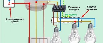
Connection diagram and connection of wires in the distribution box
As a rule, there is a distribution box with wires located on top of this switch. It can accommodate 3 cables:
- one goes down to the switch (Off)
- the second is the power coming from the switchboard (Gr.Osv)
- third - goes to the lamps in the bathroom (Light)
How to make the connection correctly, and what will be the connection diagram for all these wires in the junction box and on the fan itself? This can be schematically drawn as follows:
To connect all contacts, from the box to the ventilation installation site, you will need to lay another VVGnG-Ls 3*1.5mm2 cable.
The ends of the cable are stripped on both sides and signed.
- L-phase power
- T-phase for hood control via timer
- N-zero
There is no need to twist anything, just fit everything on the Wago clamps.
First, connect phase L to the main power cable coming from the switchboard.
Next, connect the neutral wires.
Please note that for the hood to operate correctly, a voltage of 220V must always be present at the terminals of the control board.
That is why one phase core of the cable is connected directly to the light switch.
That's why a three-core cable is used here. If you only have 2 wires going into your bathroom, you won’t be able to implement a circuit with a timer.
Phase T, which is supplied to the fan timer, is connected after the switch. That is, to the wire that goes to the lamps in the bathroom.
Thus, the ventilation is controlled through the light switch. All that remains is to correctly connect all the conductors on the fan itself.
Remove the protective decorative frame to get to the contacts.
There is a timer in the upper right corner. Immediately adjust it to the approximate operating time. Adjustment is carried out over a wide range - from 15 seconds to 45 minutes.
For some, it is turned almost to zero from the factory. As a result, the blades stop rotating immediately after the light is turned off.
People think that the hood is broken. Although it was enough to just tighten the screw.
Now connect the cables to the appropriate terminals:
- phase power conductor L - to the terminal with a similar marking
- fan timer phase - to the middle contact with the inscription T
- zero - to the remaining terminal N
Please note that if you have only 2 wires, phase and zero, then in order for the system to work at least in manual mode, you will have to make a jumper between terminals N and T.
Then the device will only work when the light keys are turned on and off. There can be no talk of any automation or time delay here.
Some other models are affected by the correct connection of the neutral - N and phase - L conductors. If your fan behaves in an unclear way and works or, on the contrary, refuses to work correctly, try swapping them.
Check the indicator light to see where exactly the phase is coming from and check again with the diagram indicated in the device passport.
Next, secure the fan and check its operation by turning the bathroom lights on and off.
Fastening is best done with glue or sealant.
Drilling holes for dowels is often problematic:
- or the holes are located close to the edge of the tile
- or there may be reinforcement in this place, and you will simply break your entire wall with a hammer drill
Here, as they say, depends on your luck.
Using an electromagnetic relay
Using a simple relay will slightly complicate the circuit, but will relieve the temperature sensor from the presence of high current. A large current will flow through the relay contacts. It is cheaper and easier to replace the relay than the temperature sensor to turn on the electric fan. To carry out the upgrade, you will need a wire and a relay with a bracket for mounting to the body.
Disconnect the temperature sensor, and the wires that were on it must be connected to the normally open pair of contacts of our relay. Half the job is done, the power part is ready. Now control. We connect one terminal of the temperature sensor to ground, but connect the second to the relay coil.
From the second terminal of the coil you need to stretch the wire to the positive terminal of the battery. It is advisable that the connection be made through a fuse, the operating current of which can be 1 Ampere. The coil consumes a small amount of current, so the worst thing that can happen is a short circuit in the wiring. Subsequently, you can connect a forced activation button in parallel with the temperature sensor, which you will install in the car interior.
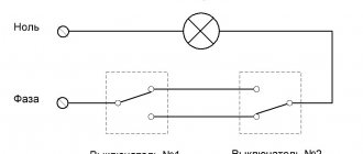
Connection via two-button switch
Another suitable option is to connect the fan through the same light switch, but with two buttons.
Here the diagram will look like this:
In fact, your hood will sit regardless of the lighting. But for this, most likely you will have to change the single-key model to a two-key model. Plus pull the extra cable from the junction box down.
There are also pitfalls here. Firstly, do not mix up the phase connection on the switch contacts.
And this happens all the time.
Secondly, do not forget that through this switching device, it is the phase that must be broken, and not the zero. Even with the correct initial connection, over time the circuit may spontaneously change.
It is enough for some local electrician, in the general switchboard or entrance wiring, to accidentally swap two conductors L and N. And in your entire apartment the “polarity” will automatically change on all switches.
What will this mean? Well, for example, when you turn on only one fan with the second button, your LED lights in the toilet may blink, flash and go out.
The effect is quite well known for LED lamps.
Semiconductor Applications
Instead of an electromagnetic relay, you can use a thyristor switch, or a design based on field-effect transistors. The essence is the same, only there are no moving contacts; their functions are performed by electrons and holes in the semiconductor crystal. But do not forget about cooling the thyristors and transistors, install radiators that will be able to provide the necessary heat transfer.
Soft engine start is a very useful function for engine control. This innovation will ensure a gradual increase in the load on the electric motor. This idea is accomplished by using PWM modulation. But along with all the innovations, you can use a second temperature sensor in the cooling system, whose response temperature is 5 degrees lower than the main one.
Connect directly
If you initially abandoned junction boxes and use recessed socket boxes for switching, then the third connection diagram will be similar, and the differences here are practically not noticeable.
It’s just that all connections are made directly in the socket box. It can be done by crimping or using the same Vago clamps, if space allows.
There are also expensive, sophisticated models with remote controls.
They are connected in two ways:
- directly from the distribution box - forced manual shutdown is performed by a button on the fan itself
- via a separate light switch button
Connection diagram for VO VAZ 2110
The circuit diagram for switching on the cooling fan of the VAZ 2110 on carburetor and injection cars is different. On cars with a carburetor engine, a thermobimetallic sensor TM-108 is used for this, and on cars with an injection engine, control is carried out by a controller.