Often a situation arises when it is necessary for the light bulbs in one of the rooms to be turned on from different places. For such cases, on flights of stairs there are pass-through switches, which are difficult to install, so it is usually impractical to install such switches in apartments.
It is much easier to turn on several light bulbs from one regular switch. How to connect two light bulbs to one switch will be discussed in this article.
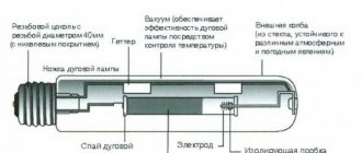
Switch device
The main element of the switch is the working part, mounted in the socket box. It is a metal structure with an attached drive. The drive is used to turn the device on and off. The drive is a moving contact that closes and opens an electrical circuit between two static contacts.
The first contact is called incoming: it is connected to a phase from the mains. The second contact (outgoing) is connected to the phase conductor coming from the lighting device. When the switch is positioned correctly, both fixed contacts are initially in an open state. When you press the device button, the moving contact provokes the closure of both fixed contacts. As a result, current flows through the closed circuit of their electrical network to the light bulb, and it lights up.
To ensure safety, the working part of the switch is housed in a housing made of dielectric material. The cases are made of plastic or porcelain.
Other components of the switch are the frame and keys. These elements are usually made from plastic. The keys are fixed on the drive of the working part. Moving as a result of pressing, the key changes the position of the contact, which leads to turning the light on or off.
The frame is designed to prevent a person from accidentally touching the switch contacts. In other words, the frame acts as a barrier between the energized elements and the person. The frame is fixed with screws or latches made of plastic.
The only difference between a two-key device and a single-key device is the presence of a pair of output contacts. Each contact is connected to a phase conductor of one of the lamps.
Regular switch for one lamp
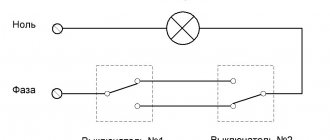
The figure below shows a diagram of connecting a light bulb to a regular light switch.
The switch is installed in a phase gap. Zero is directed to the lighting fixture. If you set the switch to zero, the contacts will soon burn out. The reason is the increased load when electricity passes through the zero contact.
Another reason for breaking a phase conductor is the need to quickly disconnect voltage from the consumer in the event of an emergency. Zero does not allow the system to be de-energized, but only opens the circuit.
Note! Electrical installation work should only be carried out in a de-energized electrical network. If it is not possible to determine the phase conductor by color scheme, it is allowed to supply current to carry out “ringing”. Before checking, you need to make sure that there are no short circuits in the exposed wiring.
Two lamps per switch
The diagram for connecting two lamps to one switch is similar to the rules for connecting one lamp. The neutral conductor is sequentially directed from the junction box through all lighting sources. The phase wire running through the switch is connected to the second contacts of the light bulbs.
The contacts must be connected as securely as possible. It is recommended to use terminal blocks. Connections are made with screws or Wago blocks (the conductor is pressed with a spring).
Note! It is unacceptable to twist wires of different metals (copper and aluminum). Otherwise, the result of such actions will be an oxidation process, which will lead to loosening of the contact and overheating.
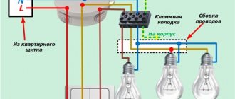
The diagram below shows the connection of two light bulbs to a single-key switch.
Each light source has a marking indicating the load limit. This information must be kept in mind when calculating the total power of connected lighting fixtures.
Main conclusions
Now you know how to connect two working light bulbs to one switch. The exact connection method depends on additional nuances. However, the general principle of action is the same: it is necessary to follow safety rules and connect wires of the same type.
Situations where one switch controls two lighting fixtures at once occur quite often. The only difference is that sometimes it is necessary to operate both lamps simultaneously with one switch, while in other cases it is necessary for each lamp to light up separately. This means that in the first case we will need a single-key switch, and in the second we will have to install a device with two keys. Let's talk about each of them separately and consider in detail how to connect two light bulbs to one switch.
The ability to connect two light bulbs to one switching device at once allows you to save materials, time and effort, because you don’t have to install a second switch, lay extra wires, or drill additional holes and grooves in the walls.
Separate lighting
A similar scheme is often used in office buildings, where it is necessary to separately illuminate many local areas. The separate lighting scheme is not particularly complicated, although it requires special knowledge.
The switch is placed in a phase break. The devices are equipped with one input and two output voltage contacts. The phase wires after the switch go to the lighting fixtures. The neutral conductor will be common to all light sources in the room.
As a result, pressing one of the keys turns on only the devices connected to a specific phase. Other light sources do not turn on.
Serial connection
You can connect spotlights in series, although this is not the best solution. Despite the fact that this type of connection requires a minimum number of wires, it is practically not used in everyday life. This is because it has two significant drawbacks:
- The lamps do not glow at full strength because they are supplied with reduced voltage. How much reduced depends on the number of connected light bulbs. For example, if three lamps are connected to 220 V, you need to divide by 3. This means that each lamp receives 73 V. If 5 lamps are connected, divide by 5, etc.
Series connection principle
It is for these reasons that this type of connection is used exclusively in Christmas tree garlands, where a large number of low-power light sources are collected. You can, of course, use the first disadvantage: connect 18 or 19 12 V light bulbs in series to a 220 V network. In total they will give 220 V (with 18 pieces 216 V, with 19 - 228 V). In this case, you don’t need a transformer, which is a plus. But if one of them burns out (or even the contact deteriorates), it will take a long time to find the cause. And this is a big minus that negates all the positive aspects.
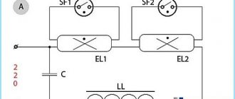
Diagram of serial connection of light bulbs (spotlights)
If you decide to connect spotlights in series, this is easy to do: the phase bypasses all the lamps one after another, zero is supplied to the second contact of the last bulb in the chain.
If we talk about the actual implementation, then the phase from the distribution box is supplied to the switch, from there to the first spotlight, from its second contact to the next... and so on until the end of the chain. The neutral wire is connected to the second contact of the last lamp.
Diagram of sequential connection of spotlights via a single-key switch
This scheme has one practical application - in the entrances of houses. You can connect two incandescent light bulbs in parallel to a regular 220 V network. They will glow incandescently, but will burn out extremely rarely.
Chandelier with multiple arms
To connect a multi-lane lighting device using a two-key switch, you will need a three-wire conductor. One core is shortened so that it goes into the junction box, and a couple of other wires should reach the switch.
The phase wire is directed to the breaker. The outgoing conductors are fixed in the terminal blocks of the switch. The lighting device comes with an output of three wires: neutral and two phase. The zero from the distribution box is directed to the zero contact, and the outgoing wires from the switch are connected to the phases of a multi-arm chandelier.
The connection diagram for a chandelier with five arms is shown in the figure below.
The result is a connection where pressing one key only turns on a pair of lamps. Another key controls three lamps. If you want to turn on all the lights, you must press both keys. Ultimately, this design provides a choice of three light intensity options: with two, three or five bulbs.
In retail chains there are switches with three keys. Their connection diagram is a little more complicated, but generally similar to those given earlier.
Parallel connection
In most cases, a parallel circuit for connecting spotlights (lamps) is used. Even though a large number of wires are required. But the voltage is supplied to all lighting devices at the same level; if one burns out, one does not work, all the others work. Accordingly, no problems with finding the location of the breakdown.
Parallel connection diagram for spotlights
How to connect spotlights in parallel
There are two ways to connect in parallel:
- Ray. Each lighting fixture has a separate cable (two or three wires, depending on whether you have a ground connection or not).
- Trailed. The phase coming from the switch and the neutral from the panel go to the first lamp. A piece of cable goes from this lamp to the second one, and so on. As a result, four pieces of cable are connected to each lamp, except the last one.
Methods for implementing parallel connection
Radial
The beam connection scheme is more reliable - if problems occur, then only this light bulb does not light up. There are two disadvantages. The first is high cable consumption. You can put up with it, since the wiring is done once and for a long time, and the reliability of such an implementation is high. The second disadvantage is that a large number of wires converge at one point. High-quality connection of them is not an easy task, but it can be solved.
You can connect a large number of wires using a conventional terminal block. In this case, a phase is supplied from one side and, using jumpers, it is distributed to the required number of contacts. On the opposite side, the wires going to the light bulbs are connected.
Methods for connecting wires in radial design
In almost the same way, you can use Vago terminal blocks for the corresponding number of contacts. You need to select a model for parallel connection. It is better if they are filled with a paste that prevents oxidation.
This method is good - it’s easy to implement (strip the wires, insert them into the sockets and that’s it), but there are a lot of low-quality fakes, and the originals are expensive (and it’s not a fact that they will sell you the original). That's why many people prefer to use a regular terminal block. By the way, there are several types, but carbolite ones with a protective screen are considered more reliable (they are black in the picture above).
And the last acceptable method is to twist all the conductors with subsequent welding (soldering will not work here, since there are too many wires, it is very difficult to ensure reliable contact). The downside is that the connection is permanent. If something happens, you will have to remove the welded part, so you need a “strategic” supply of wires.
An example of a beam connection for spotlights
To reduce cable consumption with the radial connection method, a line is drawn from the switch to the middle of the ceiling, fixed there, and wires are routed from it to each lamp. If you need to make two groups, install a two-key (two-position) switch, draw a separate line from each key, then turn off the lamps according to the chosen circuit.
Daisy chain connection
Daisy chain connections are used when there are a lot of lamps and it is very expensive to run a separate line to each one. The problem with this method of implementation is that if there is a connection problem in one place, all others also become inoperative. But localization of the damage is simple: after a normally working lamp.
Read also: Bta12 600b connection diagram
Actual implementation of parallel connection in a daisy chain method
In this case, you can also divide the lamps into two or more groups. In this case, you will need a switch with the appropriate number of keys. The connection diagram in this case does not look very complicated - just add one more branch.
How to connect spotlights to a double switch
Actually, the diagram is valid for both methods of implementing parallel connection. If necessary, you can make three groups. There are also such three-position switches. If you need four groups, you will have to install two two-position ones.
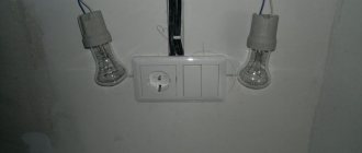
Connection from an outlet
In some cases, you need to connect an additional lighting fixture with a dedicated switch. In this situation, connecting from an existing outlet will do.
When installing a single-key switch, you will need a two-wire wire and a switching device. For a voltage breaker installed above the socket, zero and phase are removed from it. The phase wire is interrupted inside the switch, and the neutral wire is left intact. Other lighting devices in the circuit are provided with power in a similar way to the above circuits.
For electrical installation work, you will need three wires (zero and two phases). For a three-key switch, one more phase core is required.
Preparatory work
No matter how many keys your switch has (one, two or three), the preparatory work will be the same.
To begin with, you need to install a general distribution box and a mounting box for the switching device in the room; it is also called a socket box:
- If the walls in your room are made of PVC, plasterboard sheets, wood or MDF panels, install a special bit with serrated edges on a drill and make a hole. Insert the mounting box into it and fix it to the wall using self-tapping screws.
- For concrete or brick walls, make a hole using a hammer drill or drill with an attachment that works on concrete surfaces. But in this case, the mounting boxes must also be fixed using gypsum or alabaster mortar
As a rule, the installation of holes is carried out simultaneously with the laying of grooves. This is done purely for aesthetic reasons; there is a lot of dirt from such construction work, and it’s better to spray it once and clean it up. Grooves are grooves in the wall surface into which connecting wires will then be laid. They can be done using various tools:
- Hammer and chisel. This is an old ancestral method, its advantage is the complete absence of costs for purchasing tools (every man has a hammer and chisel). The disadvantage of this method of gating is that it takes a lot of time and effort.
- Bulgarian. This tool is often called the worst of the best. It’s convenient that grooves can be made quickly and without much effort. But it is from the grinder that there is a lot of noise and dust, and besides, it is not possible to make grooves of the same depth along the entire length, and it is almost impossible to work with the grinder in the corners of the room. So choose such a power tool as a last resort.
- Hammer. All you need is to purchase a special attachment for it - a strober or a spatula. In all other respects there are no shortcomings, it’s fast, convenient, the grooves are more or less even.
- Wall chaser. This is the ideal tool for this type of work. Works efficiently, safely and quickly. The grooves are smooth, there is no dust, since the wall chaser is connected to a construction vacuum cleaner. They are comfortable to work with and the tool does not make much noise. The only drawback is the high price. But there are services where you can rent a wall chaser.
Briefly about gating walls using the tools listed above is described in this video:
It is necessary to lay two-core wires into the grooves and fix them with cement or alabaster mortar.
So, the preparatory work is completed, the boxes are mounted, the wires are laid, and you can connect the light bulbs and switch.