It would be appropriate: in a corridor to connect three rooms to lighting at once - a bathroom, toilet and kitchen, if they are located close to each other; if the room has a multi-arm chandelier or combined main and additional lighting; when the ceiling is made at several levels; if a long corridor consists of three parts; if you need to control the lighting of three rooms from one point.
With a light indicator - serve as a beacon for finding a switch or signaling in which rooms the lights are on. The round pieces inside the box are soldered wires, made in the form of twists with welding, crimped with self-clamping insulating caps, connected with terminals or a screw connection.
The switch consists of: a protective part - a key and a frame; working part - mechanism for fixing wires and housing. Connecting wires to a three-key switch There are various models of triple switches: for external, internal installation or combined - in one housing with a socket. How to connect a three-key switch? How to install in a socket box? Three-key devices are convenient to use to control multi-arm chandeliers.
Simplification of the installation procedure for a three-key switch is achieved by reducing labor costs when creating a common technological niche for placing the core of the device and laying an electrical cable to it.
When the ends of the probes are closed, the device emits a sound signal, which is very convenient, since there is no need to look at the device display.
The changeover contact of the second switch is connected to the lamp, and the lamp, in turn, is connected to the neutral wire of the supply network.
According to the rules for installing electrical appliances PUE, the device must be connected in such a way that the phase current conductor opens. Cross-switch diagram and connection
How to connect a chandelier with 3 lamps to a switch with 1 key
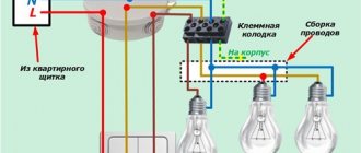
Connecting this lighting device to a single-key switch is carried out in several stages. First of all, you need to deal with the wires in the chandelier itself. Here, each cartridge is connected to two wires - phase and neutral, the insulation of which is painted in different colors. Most often, the blue conductor is considered zero, and the remaining colors indicate phase. In accordance with the rules, the phase is connected to the central contact of the cartridge, and the zero is connected to the side.
The chandelier arms are attached to the body, where all the wires are combined. Their distribution for a single-key switch is as follows: phase wires are combined into one group, and neutral wires into another. It should be remembered that zero is supplied to the chandelier directly, bypassing the switch. Subsequently, the nodes of the phase and neutral wires coming out of the chandelier are connected to the corresponding conductors of the electrical network.
The distribution box also has two wires - phase and neutral. It supplies a two-core cable separately to the chandelier and separately to the switch. The lamp is supplied with phase and zero, and the switch is supplied with only phase to both contacts. Closing and opening the contacts allows you to turn the light bulbs on and off.
Converting a double switch into a triple device
Connection diagrams for double and triple switches
In order to make the most of switching products, some users try to make a triple switch out of a double switch. Such a rework does not require much effort or a lot of time. You just need to replace the double device with a new model:
- Buy a switch with three keys in the store.
- Dismantle the old double product.
- Install a new triple switch in its place.
When remaking, you will need to lay an additional line towards the junction box.
It is needed to connect to a third lighting fixture or group. You can try to hide it in the thickness of the walls, but the gating procedure is associated with large labor costs for making grooves for the cable. It is much cheaper and easier to lay pieces of plastic cable channel from the outlet to the box, and from it to the chandelier. After fixing it on the walls (the covers are first removed), the wire sections are laid to the required places and then connected to the free terminals. Upon completion of installation, all that remains is to close the cable channels with covers and check the switch for functionality
Three-key switches are universal devices through which it is possible to significantly expand the functionality of switching units.
How to connect a chandelier with 3 lamps to a switch with 2 keys
Before installation begins, you need to decide which lamps will be turned on by each key. In this case there are very few options. As a rule, one key turns on one light bulb, and the other turns on two at once. You can also change the functions of the keys among themselves for ease of use.
Typically there are 3 conductors or a three-core cable coming out through the floor slab. In modern houses, 4 yellow ground wires with a green stripe are added to them. The remaining wires are determined using an indicator screwdriver with the switch in the on position. The wire on which there is no voltage will be zero, and all the rest will be phase.
In the chandelier itself, the phase wires can be combined in advance into groups. Of the three bulbs, two are connected to each other to turn on simultaneously. If this is not done, the wires must be distributed independently. Next, the neutral wires of the chandelier and the network are connected to each other. Then the phases of the chandelier and the switch are connected. After this, a functionality check is performed.
If you need to change the functions of the keys, just swap the wires. If both keys are turned on at the same time, all the lights will light up at once. All connections are made with the protective device disabled.
How to connect a chandelier with 3 lamps to a switch with 3 keys
This diagram is an expanded version of the previous connection, and all the main steps remain the same. In this case, four wires come from the ceiling, and there are three or more in the chandelier. The fourth yellow-green wires relate to grounding and are designated PE. They just need to be connected to each other. If there is no ground wire in the chandelier, then the same wire on the ceiling must be cut and carefully insulated. The remaining conductors are connected according to the same scheme described above.
In some cases, the fourth wire coming from the ceiling can act as another phase. This option is most suitable when using a three-key switch. It makes it possible to control all the light bulbs in the chandelier. A three-key switch makes it possible to turn on and off each independent group of lamps. To do this, you will need another free core in the ceiling wiring, which has already been mentioned. All actions will be the same as for the two-key design. The phase of the home network is connected to the input contact of the switch, and from the output the phase goes to each group of lamps.
When installing a switch, you must follow electrical safety rules to avoid electric shock. Therefore, before performing electrical installation work, you need to disconnect the entire electrical network. You can check the absence of electricity using an indicator screwdriver.
Thus, connecting a chandelier with three lamps is not particularly difficult. The most important thing is to carefully study the diagram and, if possible, use only solid cables, with a minimum number of extensions and twists. As a result, the operation of the chandelier will be long and safe.
From this article you will learn what cross-section of wires is needed to connect to a chandelier, how to ring and determine the phases on the ceiling: we are looking for a ground wire, we are looking for phases and zero, the designation of the chandelier wires.
How to connect a chandelier in a simple way, rules for connecting wires, connecting a 2,3,4,5, 6 chandelier to a single and double switch and many other questions.
DESIGN FEATURES OF THE CHANDELIER
Chandeliers are most often used as lighting devices in residential premises - multi-lamp lamps designed for installation on the ceiling.
A chandelier is a structure that connects several lighting elements - light bulbs - to provide good lighting in the room.
If you use a regular light bulb in a room, then to ensure proper lighting you will need to install a powerful lighting element, and even then, if the room is large, it will not be enough.
But such light is not always needed, so the best option is to use several lamps.
But in the case of using ordinary light bulbs, each of them will have to run its own wire or branch from the junction box.
But if you install a chandelier, the design of which involves installing several light bulbs, then the complexity of the connection will be the same as for one or more light bulbs.
But at the same time, all lighting elements included in the design will be powered, and from one wire.
And all because the wiring branching occurs at the entrance to the chandelier, and not in the junction box.
Well, don’t discount the aesthetic side of the issue. A lonely light bulb hanging on the ceiling looks dull, or maybe a beautiful chandelier.
Read also: Copper bracelets: benefits and harms reviews
To get good lighting in a room with a perfect combination of lighting fixtures with the interior, it is not enough just to purchase a suitable chandelier, you also need to hang it and connect it correctly.
Therefore, next we will consider how to properly connect the chandelier.
WHAT IS TO BE CONSIDERED BEFORE CARRYING OUT WORK?
Let’s immediately identify a few key points that should definitely be taken into account:
- Design of a chandelier (They are usually divided among themselves by horns - elements at the end of which sockets for light bulbs are installed. As mentioned above, the division into power branches for light bulbs is made at the entrance to the chandelier, and the horns can be considered these branches. By design, chandeliers are hornless, two-, three-, four- and five-horn);
The switch used (the method of connection depends on this. If, for example, the switch is a single-key switch and when the light is turned on, all the lamps of the chandelier will light up, then this is one connection diagram, but the use of two- or three-key switches, each key of which will be responsible for the operation of a specific group lamps require the use of a slightly different connection method);
- The presence of additional equipment in the design of the chandelier (a fan or a remote control unit makes certain adjustments to the connection diagram);
- Features of the electrical network of the house (in old buildings, two-wire wiring is usually used, and in new or restored buildings the number of wires is already three).
- Breaking the circuit with a switch is carried out only through the phase line, and the neutral conductor and grounding conductor (if any) go directly to the consumer;
- For each branch, a separate phase wire is laid at the output of their switch (It is separated in the switch itself. A single-key switch has one phase conductor at the output, a two-key switch has two, a three-key switch has three). This affects the wire used leading from the switch;
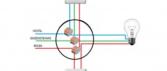
- On the terminal blocks of the chandeliers you can find the designation of the terminals, which makes the connection easier (the marking “L” indicates that the terminal is phase, “N” is neutral, “PE” is grounding).
And one more thing - it’s one thing to simply remove the old lighting fixture and connect a new one in its place, and quite another thing to completely create a lighting power line, including laying wiring from the distribution board, installing switches, junction boxes and lighting fixtures, and then connecting them into one network.
We will not delve into the specifics of independently installing the power supply branch of a chandelier, since we are more interested only in how to connect the lighting elements, although some points regarding wiring will be touched upon.
HELPFUL INFORMATION
Let us immediately point out some features that can help:
Now directly, how to connect the chandelier to the switch.
Let's assume that the line is made in advance, the switch is in place, and 2 or 3 wires stick out from the ceiling (with the third wire being “ground”).
In general, the connection diagram is the simplest - “one-key switch - 1 lighting fixture.”
If the chandelier is armless (with 1 lamp), then the connection method does not differ at all from powering a simple light bulb.
SINGLE KEY SWITCH – 1 CHANDELIER
Before starting work, you should determine which wire is which. It would be good if modern wiring with color differences between the cores was used. At the initial stage, only “land” is of interest.
If the electricians did not mess anything up, the ground wire will have a yellow-green braid.
But you will have to figure out the phase and zero yourself and for this you will only need an indicator screwdriver, but all precautions should be taken, since the test is done in live wiring.
Therefore, before applying voltage, you should make sure that the ends of the wires are separated in different directions and do not touch each other.
And only after this can voltage be applied (you also need to turn the switch to the “on” position).
After we touch the ends of the wiring with the tip of the indicator screwdriver, the indicator light that comes on when touched will indicate that the core is phase, which means the second one is zero.
If there are three wires at the output, and it is not clear which of them is zero and ground, you can use a test light to determine it (we connect a two-core wire to a regular 220 lamp through a socket). Then we identify the phase with an indicator screwdriver.
And then we connect the light bulb to the phase wire and one of the other two.
If the lamp lights up after applying voltage, then the second wire will be zero (if it doesn’t light up, the “ground” is connected to the control). For reliability, the wires should be swapped.
After determining where each wire is, all that remains is to connect them to the corresponding terminals of the chandelier terminal block, and then secure it to the ceiling hook. In general, everything is as simple as shelling pears.
The diagram for connecting the chandelier to two terminals is as follows:
If the circuit is three-wire, then the connection is made like this:
Now let’s assume that the chandelier is a two-arm chandelier and you need to connect it to a single-key switch.
Each horn is a branch and two wires must come from it (phase and zero), but the “ground” is connected to the body, so it does not go to the branches.
Let's assume that there are blue and brown wires coming from each horn.
To connect the chandelier, you need to separate the wires of the horns by color and twist them together (the blue ones are separate from the brown ones).
Then we connect them to the power line, and it does not matter what color the wires will be phase and neutral.
For example, we connect the brown wires through the block to the phase conductor, and the blue wire to the zero.
Then we isolate everything and check its functionality. Here we note that with such a connection, no matter how many bulbs there are in the chandelier, they will all light up when turned on.
It happens that the third wire in a chandelier or wiring is superfluous (ground is not provided in the lighting fixture or power line).
In the case of a chandelier, we simply ignore this output (this will not affect the performance in any way), but the grounding conductor of the wiring will need to be insulated.
In general, this is a general diagram for connecting a chandelier and it is identical for everyone, but there are some nuances that will be indicated below.
A little about wiring connections. To do this, you can use either terminal blocks or conventional twisting followed by insulation with protective caps.
Each connection method has its own advantages and disadvantages.
Terminals are more convenient for installation, but it is not always possible to install it.
The twist is more compact in size, but it is not always possible to twist the wires well.
TWO-KEY SWITCH – CHANDELIER
Now let's talk about how to connect a chandelier to a two-key switch.
Since the number of lamps and their division into groups can be very different, we will consider several options:
Read also: Life hack on how to sharpen a razor yourself
- “The switch is a chandelier with two lamps.” Since it was mentioned that in such a switch the phase is divided into two lines, for which a separate key is intended to open the circuit, then 3-4 wires should come out on the ceiling (two phases, zero and ground). It is assumed that each key will power its own lamp. To connect everything, you must first decide where the phase and neutral terminals are. We take the wires of each of the horns, separate two of the same color (for example, blue), twist them and connect them to the zero terminal of the power line. All that remains is to deal with the brown wires of the chandelier. Each of them must be individually connected to the phase terminals of the wiring. There should be three connections in total - two phase (with brown wires) and one neutral (with double blue wires);
“The switch is a three-arm chandelier.” The peculiarity of this scheme comes down only to the correct separation of the wires. Since there are three lamps, and only two keys (and therefore two phase wires), one of them will power two chandelier bulbs at the same time. As a result, we also get three connections. First we connect zero. To do this, we select one wire of the same color (blue) for each horn, twist them all together and connect them to the neutral wire. That leaves three brown wires. We twist two of them and connect them to one of the phase conductors, and the third to the second phase;
“Switch – 4-, 5-, 6-arm chandelier.” Here the connection diagram is the same as above, that is, the total number of connections will be three. As before, we twist all the wires of the same color (blue) into one twist and connect it to the neutral core (here a twist is more suitable, not a terminal block). We divide the remaining wires into two halves (for example, in a 4-arm chandelier, you can divide them so that when you turn on one key, two parallel light bulbs light up). We twist each half of the wires and connect them to one of the phase wires. We do the same with the other part of the wires.
ONE SWITCH – SEVERAL CHANDELIERS
Now let's look at how to connect several chandeliers to one switch. Here you will also have to consider the features of the power line.
For example, let’s take a single-key switch that will power three chandeliers at once.
The lighting line diagram with this switch is as follows: phase and zero go from the switchboard to the distribution box.
A wire goes into it from the phase conductor to the switch, and returns to it again.
As a result, in the box we have a zero and a phase (with a switch included in the circuit), to which we can connect the wiring leading to the consumer.
Therefore, in order to connect three chandeliers to this switch at once, it is enough to throw one common line and insert the phase and neutral wires of the lighting devices into it.
Moreover, it is better to connect each chandelier to a common line in distribution boxes (they additionally need to be installed). And then in the chandelier itself, divide it into horns (branches).
CONNECTING A CHANDELIER WITH ADDITIONAL EQUIPMENT
Now about connecting the chandelier in which the fan is mounted. This lighting device does not require anything special to connect, since the fan is the same consumer as a regular light bulb (that is, the circuit is the same as that of a two-arm chandelier).
It should be connected to a two-key switch so that you can turn off the light or fan if necessary.
Also, when connecting such a chandelier, you should read the instructions, which should indicate which of the wires going to power the fan is phase and which is neutral, and use this information when connecting.
The same applies to chandeliers that have remote control using a remote control.
Inside such a device there will be a special executive unit with a controller that receives signals from the remote control.
So, this unit requires power, and it works on the same principle as a light bulb.
But in chandeliers with LED lamps, the lighting elements operate from a 12V network with direct current. And for this purpose, the design of the lighting device contains a step-down transformer, which has phase and neutral terminals.
Connecting this chandelier is as easy as connecting a regular light bulb.
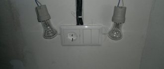
Sometimes there is a need to install a combination switch to power the chandelier, combined with an outlet.
And here the whole peculiarity lies precisely in connecting the switch itself, and not the lighting device.
Since there is an outlet, in order for it to function, both phase and zero must be supplied to it.
And if only a phase conductor was routed to a conventional switch, then a neutral conductor will also have to be routed to the combined switch. The connection diagram for such a switch is presented below.
There are times when the part of the supply wiring protruding from the ceiling is not enough to connect the chandelier. In this case, you can simply increase them.
To do this, you can take two pieces of copper wire with a cross-section of at least 1.5 mm. sq. and connect them to the line terminals using twisting. Then the connection points should be properly insulated.
SAFETY
When connecting a chandelier, do not forget about safety precautions. All work should be carried out only with de-energized wiring. Moreover, simply disconnecting the line at the switch is not enough; it must be de-energized at the distribution board.
You need to be very careful about the distribution of wiring before connecting.
If the instructions contain recommendations for connection, they must be followed.
All connections must be of high quality. If terminal blocks are used, then the clamps should be tightened well, and in the case of twists, the wires should be tightened with pliers. All exposed connections require high-quality insulation.
Functionality checks should only be carried out after all connections have been isolated.
Often a situation arises when it is necessary for the light bulbs in one of the rooms to be turned on from different places. For such cases, on flights of stairs there are pass-through switches, which are difficult to install, so it is usually impractical to install such switches in apartments.
It is much easier to turn on several light bulbs from one regular switch. How to connect two light bulbs to one switch will be discussed in this article.
Switch device
The main element of the switch is the working part, mounted in the socket box. It is a metal structure with an attached drive. The drive is used to turn the device on and off. The drive is a moving contact that closes and opens an electrical circuit between two static contacts.
Read also: DIY honing head
The first contact is called incoming: it is connected to a phase from the mains. The second contact (outgoing) is connected to the phase conductor coming from the lighting device. When the switch is positioned correctly, both fixed contacts are initially in an open state. When you press the device button, the moving contact provokes the closure of both fixed contacts. As a result, current flows through the closed circuit of their electrical network to the light bulb, and it lights up.
To ensure safety, the working part of the switch is housed in a housing made of dielectric material. The cases are made of plastic or porcelain.
Other components of the switch are the frame and keys. These elements are usually made from plastic. The keys are fixed on the drive of the working part. Moving as a result of pressing, the key changes the position of the contact, which leads to turning the light on or off.
The frame is designed to prevent a person from accidentally touching the switch contacts. In other words, the frame acts as a barrier between the energized elements and the person. The frame is fixed with screws or latches made of plastic.
The only difference between a two-key device and a single-key device is the presence of a pair of output contacts. Each contact is connected to a phase conductor of one of the lamps.
Types of switches and their advantages
Touch switch with remote control
The standard triple switch is available in the following versions:
- single device with three separate keys;
- touch triple device (or a more advanced wireless model);
- combined triple switch with socket.
The last option is an example of extended functionality, combining switching and power units.
Device with backlight function in the housing
Other versions of switches are also possible, differing in their appearance (design).
The advantages of these devices, regardless of their type, include:
- a large selection of lighting combinations;
- a variety of schemes by which they are connected to the supply line;
- ease of installation and operation.
Touch devices allow you to control the process of turning on and off by lightly touching the central part of the key; switching them does not require effort.
Wireless samples are still a rarity in everyday life, since they are very expensive. Often, special modules (dimmers) are built into “advanced” models that allow you to change the brightness of the light or backlight connected to them.
Regular switch for one lamp
The figure below shows a diagram of connecting a light bulb to a regular light switch.
The switch is installed in a phase gap. Zero is directed to the lighting fixture. If you set the switch to zero, the contacts will soon burn out. The reason is the increased load when electricity passes through the zero contact.
Another reason for breaking a phase conductor is the need to quickly disconnect voltage from the consumer in the event of an emergency. Zero does not allow the system to be de-energized, but only opens the circuit.
Note! Electrical installation work should only be carried out in a de-energized electrical network. If it is not possible to determine the phase conductor by color scheme, it is allowed to supply current to carry out “ringing”. Before checking, you need to make sure that there are no short circuits in the exposed wiring.
Two lamps per switch
The diagram for connecting two lamps to one switch is similar to the rules for connecting one lamp. The neutral conductor is sequentially directed from the junction box through all lighting sources. The phase wire running through the switch is connected to the second contacts of the light bulbs.
The contacts must be connected as securely as possible. It is recommended to use terminal blocks. Connections are made with screws or Wago blocks (the conductor is pressed with a spring).
Note! It is unacceptable to twist wires of different metals (copper and aluminum). Otherwise, the result of such actions will be an oxidation process, which will lead to loosening of the contact and overheating.
The diagram below shows the connection of two light bulbs to a single-key switch.
Each light source has a marking indicating the load limit. This information must be kept in mind when calculating the total power of connected lighting fixtures.
Transmitter connection option
Instead of connecting two light bulbs to a 220 V network, you can connect lighting fixtures to the network using 12 V frequency converters. Such devices conduct electric current to several lamps with a short pause of 1-2 seconds. At the same time, lighting devices receive electricity smoothly, without a sharp increase in load.
When can you connect the converter:
- for supplying current to incandescent lamps;
- for providing electricity to halogen light bulbs.
The switch is installed in the circuit before the converter. Otherwise, the contacts may burn out. This should happen because the current is greater at low voltage. In addition, the converter provides a slight delay in the incoming voltage. If a breaker is added after the switch, then the gradual, smooth start of the light bulbs will not be ensured. Thus, the whole point of including the converter in the circuit is lost.
If a two-key switch is mounted, then you will need to connect 2 converters. Power will have to be supplied to it through a second line. “Zero” will remain common.
Separate lighting
A similar scheme is often used in office buildings, where it is necessary to separately illuminate many local areas. The separate lighting scheme is not particularly complicated, although it requires special knowledge.
The switch is placed in a phase break. The devices are equipped with one input and two output voltage contacts. The phase wires after the switch go to the lighting fixtures. The neutral conductor will be common to all light sources in the room.
As a result, pressing one of the keys turns on only the devices connected to a specific phase. Other light sources do not turn on.
Chandelier with multiple arms
To connect a multi-lane lighting device using a two-key switch, you will need a three-wire conductor. One core is shortened so that it goes into the junction box, and a couple of other wires should reach the switch.
The phase wire is directed to the breaker. The outgoing conductors are fixed in the terminal blocks of the switch. The lighting device comes with an output of three wires: neutral and two phase. The zero from the distribution box is directed to the zero contact, and the outgoing wires from the switch are connected to the phases of a multi-arm chandelier.
The connection diagram for a chandelier with five arms is shown in the figure below.
The result is a connection where pressing one key only turns on a pair of lamps. Another key controls three lamps. If you want to turn on all the lights, you must press both keys. Ultimately, this design provides a choice of three light intensity options: with two, three or five bulbs.
In retail chains there are switches with three keys. Their connection diagram is a little more complicated, but generally similar to those given earlier.
Two-gang switch
The use of a two-key switch is possible in rooms with separate lighting when connecting a multi-light chandelier or a separate bathroom, where it is located between the doors to the bathroom and toilet. Naturally, it makes no sense to install two conventional switches side by side if it is possible to place a more compact device.
Separate room lighting
Such lighting is most often used in office spaces, where there is more natural light near the window, but at the same time, the working day in winter is short. The connection diagram in this case is not complicated, but requires certain knowledge.
The switch is also installed in the phase wire break. Such devices have one voltage input and two voltage output contacts. The phases that have passed through the switch are distributed among the luminaires depending on the project or the wishes of the owner.
Zero is common to all lighting fixtures in the room. Then, when one of the keys is turned on, power will be supplied only to the devices connected to this phase, while the rest will not work. Lighting devices in a separate bathroom are also connected according to a similar scheme.
Multi-arm chandelier
When connecting a multi-arm chandelier via a two-key switch, a three-core wire is required. One of the cores is shortened so that it can be inserted into the distribution box (usually above the switch), and the other two reach the switching device itself.
As in the previous case, a phase is supplied to the breaker, and the outgoing wires are fixed in the terminal blocks of the switch. The chandelier itself includes a lead of three wires, one of which is neutral, and the other two, phase, are connected (in the example of a five-arm) to two and three light sources, respectively. The direct zero from the distribution box goes to the zero contact, and the wires coming out of the switch are connected to the phase wires from the chandelier.
The result is a connection in which, if you act one by one, pressing one of the device’s keys turns on only two light bulbs, and pressing the other turns on three, but if stronger lighting is needed, you can turn on both keys.
Thus, with the help of such a breaker, three options for lighting intensity are produced, which ensures a variety of illumination.
There are also switches on sale that have three keys. Their installation diagram is a little more complicated, but similar to those given above. With their help, you can implement more lighting options.
Connection from an outlet
In some cases, you need to connect an additional lighting fixture with a dedicated switch. In this situation, connecting from an existing outlet will do.
When installing a single-key switch, you will need a two-wire wire and a switching device. For a voltage breaker installed above the socket, zero and phase are removed from it. The phase wire is interrupted inside the switch, and the neutral wire is left intact. Other lighting devices in the circuit are provided with power in a similar way to the above circuits.
For electrical installation work, you will need three wires (zero and two phases). For a three-key switch, one more phase core is required.
Purpose and design
Often, connecting a three-key model is used to control the lighting of different rooms from one place.
The main purpose of a triple switch is to install lighting devices with several groups of loads (light bulbs, for example) in switching circuits. The simplest scheme for switching it on involves installing it in a phase line break, to which three different illuminators are connected (one for each changeover mechanism with a key). In addition, this device can be used in the following situations:
- be part of a device called an “electrical extension tee”;
- to control the switching on of light in three adjacent rooms from one common corridor;
- if necessary, switch several loads at once when connecting them from an outlet;
- for controlling electrical circuits in which the number of energy consumers exceeds the number of keys (five lights, for example).
In the latter case, the lamps are divided into groups, each of which is switched by a separate button.
From a design point of view, a three-key switch is a triple rocker mechanism consisting of identical units. When the position of one of the buttons changes, the internal circuit of the product is closed, after which the voltage supplied to the group is transferred to the corresponding load.
If you return the key to its original state, the previously formed electrical circuit opens, and the light bulb connected to it goes out. The same thing happens with all other groups of the three-key switch.
The peculiarity of the switching mechanism is that its input contacts are combined into one block, and the upper terminals are designed separately. This allows three independent loads to be connected to the switch.