Currently, many home devices require a stable voltage connection of 3 volts and a load current of 0.5 amperes. These may include:
- Players.
- Cameras.
- Phones.
- DVRs.
- Navigators.
These devices are united by a power source in the form of a rechargeable battery or 3-volt batteries.
How to create power from a household network at home without spending money on batteries or batteries? For these purposes, there is no need to design a multi-element power supply, since special microcircuits in the form of stabilizers for low voltages are commercially available.
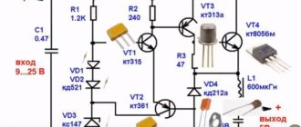
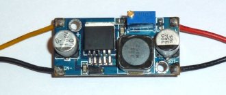
3 volt stabilizer circuit
The depicted circuit is made in the form of an adjustable stabilizer, and makes it possible to create an output voltage from 1 to 30V. Therefore, this device can be used to power various devices for 1.5 V power supply, as well as for connecting 3 V devices. In our case, the device is used for a player, the output voltage is set to 3 V.
Chip modifications
Modifications of the microcircuits included in the series differ in their housing. Most unipolar unregulated stabilizers are made in the TO-220 “transistor” package. It has three outputs, which is not enough in all cases. Therefore, some of the microcircuits were produced in multi-pin packages:
- DIP-14;
- 4-2 - the same, but in a ceramic shell;
- 16-15.01 – planar housing for surface mounting (SMD).
In such versions, mainly adjustable and bipolar stabilizers are produced.
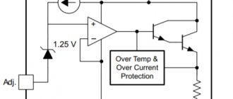
Circuit operation
Using a variable resistance, the required output voltage is set, which is calculated by the formula: U out=1.25*(1 + R2 / R1). Instead of a voltage regulator, the SD1083 / 1084 microcircuit is used. Without changes, domestic similar microcircuits 142KREN 22A / 142KREN 22 are used, which differ in output current, which is an insignificant factor.
For the microcircuit to operate normally, it is necessary to install a small radiator for it. Otherwise, when the output voltage is low, the regulator operates in current mode and heats up significantly even without load.
Pin assignment and operating principle
According to the principle of operation, all microcircuits in the series belong to linear regulators. This means that the input voltage is distributed between the regulator element (transistor) of the stabilizer and the load so that the voltage drops across the load, which is set by the internal elements of the microcircuit or external circuits.
If the input voltage increases, the transistor closes; if it decreases, it opens slightly so that the output voltage remains constant. When the load current changes, the stabilizer acts in the same way, maintaining the load voltage constant.
This scheme has disadvantages:
- The load current constantly flows through the regulating element, so the power P=Uregulator⋅Iload is constantly dissipated on it. This power is wasted and limits the efficiency of the system - it cannot be higher than Uload/Uregulator.
- The input voltage must exceed the stabilization voltage.
But the ease of use and low cost of the device outweigh the disadvantages, and in the range of operating currents up to 3 A (and even higher), it makes no sense to use anything more complex.
For voltage regulators with a fixed voltage, as well as for adjustable stabilizers of new developments (K142EN12, K142EN18) in three- and four-pin versions, the pins are designated by the numbers 17,8,2. This illogical combination was obviously chosen to match the pins with microcircuits in DIP packages. In fact, such “dense” markings are preserved only in technical documentation, and on the diagrams they use terminal designations corresponding to foreign analogues.
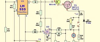
Switchable stabilizer on a chip
This scheme is the easiest and simplest. It can be mounted independently on a regular LM 317 LZ chip. By turning off and on the resistance in the feedback circuit, two different output voltages are generated. in this case, the load current can increase to 100 milliamps.
We must not forget about the pinout of the microcircuit, since it differs from conventional stabilizers.
Connection diagram KR142EN5A
As you can see, the DA1 microcircuit is connected according to a standard circuit in the positive arm of the CH. With the advent of specialized microcircuits, the situation has changed. Manufactured microcircuit voltage stabilizers are capable of operating over a wide range of output voltage and current; they often have a built-in protection system against overcurrent and overheating - as soon as the temperature of the microcircuit crystal exceeds the permissible value, the output current is limited.
If we assume that the voltage at the emitter junction of transistor VT1 and the forward voltage of diode VD1 are approximately the same, then the current distribution between the DA1 microcircuit and the control transistor depends on the ratio of the resistance values of resistors R2 and R1.
All of the above serves only for the preliminary selection of a stabilizer; before designing a power supply, you should familiarize yourself with the full reference characteristics, at least in order to know exactly what the maximum permissible input voltage is, whether the stability of the output voltage is sufficient when the input voltage, load current or temperature changes.
SN with adjustable output voltage, the output voltage of which can be adjusted from 0 to 10 V. In such cases, you can facilitate the operation of the microcircuit by connecting an external control transistor to it.
In this case, it is necessary to take into account the differences in pinout of microcircuits for positive and negative voltages. To achieve a very high ripple suppression ratio, the control input can be shunted with a capacitance. This circuit solution is borrowed from [1]. Operation of voltage stabilizer KREN8B
A little more about the module and how it works
This is a semiconductor diode that has the property of producing a certain voltage value regardless of the current supplied to it. This statement is not completely true for absolutely all options, because different models have different characteristics. If you apply a very strong current to an SMD module (or any other type) that is not designed for this purpose, it will simply burn out. Therefore, the connection is made after installing a current-limiting resistor as a fuse, the value of the output current of which is equal to the maximum possible value of the input current to the stabilizer.
It is very similar to an ordinary semiconductor diode, but has a distinctive feature - its connection is done in reverse. That is, the minus from the power source is supplied to the anode of the zener diode, and the plus to the cathode. Thus, a reverse branch effect is created, which provides its properties.
A similar module is a stabistor - it is connected directly, without a fuse. It is used in cases where the parameters of the input electricity are precisely known and do not fluctuate, and the output also produces an exact value.
Main characteristics of KR142EN5A
- Output voltage: 5V
- Output current: 2A
- Maximum input voltage: 15 V
- Input-output voltage difference: 2.5V
- Power dissipation (with heatsink): 10 W
- Output voltage accuracy: 0.05V
Maximum operating values of KR142EN5A:
- Power dissipation: internally limited
- Storage temperatures: -55 … +150С
- Range (operating) temperatures of the crystal: -45 … +125С
Features of the KR142EN5A stabilizer:
- Correction of the safe operation area of the output transistor
- Internal protection against crystal overheating
- Internal short circuit current limiter
Indication of passport characteristics
They are also the main indicators of domestic and imported zener diodes, which must be used as a guide when selecting a zener diode for a specific electronic circuit.
- UCT – indicates what nominal value the module is capable of stabilizing.
- ΔUCT – used to indicate the range of possible incoming current deviation as a safe damping.
- ICT – parameters of the current that can flow when the rated voltage is applied to the module.
- ICT.MIN – shows the smallest value that can flow through the stabilizer. In this case, the voltage flowing through the diode will be in the range UCT ± ΔUCT.
- ICT.MAX – the module is not able to withstand a voltage higher than this value.
142EN1, 142EN2, 142EN3, 142EN4
The required output voltage is set with variable resistor R2.
The peak value of the current through battery GB1 depends on the resistance of resistor R3 with a resistance of 1 Ohm indicated on the diagram - 0.6 A. It has become possible to equip each board of a complex device with its own voltage stabilizer CH, and therefore use a common unstabilized source to power it.
At the moment the power is turned on, the capacitor S3 begins to charge, so the transistor is open and bypasses the lower arm of the divider R1R2. Typically, an input capacitor is not needed if the stabilizer housing is within 15cm of the input filter capacitance, otherwise it is required.
If we assume that the voltage at the emitter junction of transistor VT1 and the forward voltage of diode VD1 are approximately the same, then the current distribution between the DA1 microcircuit and the control transistor depends on the ratio of the resistance values of resistors R2 and R1. Thanks to the large input resistance of the op-amp, it becomes possible to increase the resistance of the divider R1R2 tens of times compared to the SN with the typical inclusion of the DA1 microcircuit and, thereby, significantly reduce the current consumed by it.
When operating a device with a load current of less than 0. A bipolar SN based on a unipolar microcircuit can be made according to the circuit shown in Fig. As the output current increases, this voltage drop increases, and when it reaches 0, at the moment the power is turned on, the capacitor S3 begins to charge, so the transistor is open and bypasses the lower arm of the divider R1R2.
Other topics
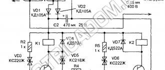
All overload protection systems remain fully operational even if the control input is disabled. MV with stepped switching. MV protected from damage by discharge current of capacitors. At the same time, the microcircuit maintains the output voltage at a level determined by its type: as the voltage increases, its regulating element closes, thereby reducing the current flowing through it, and the voltage drop across the R2VD2 circuit decreases.
In addition, an output capacitor can be added to smooth out transients. We present to your attention a somewhat unusual method of obtaining stable voltage values, 3-pin stabilizers for which either do not exist in nature or are not yet widespread. The literature offers many ways to find a way out of this situation. Behind the designations indicated in the table there may also be letters and numbers indicating certain design or operational features of the microcircuit. The total number of stabilizer elements was quite significant, especially if it was required to regulate the output voltage, protect against overload and output short circuit, and limit the output current at a given level.
All overload protection systems remain fully operational even if the control input is disabled. Last messages. If this voltage, on the contrary, increases, the process proceeds in the opposite direction and the equality of the output voltages is also restored. Proven 12 volt stabilizer for 10 rubles for LEDs and DRLs
Additional markings for glass models
Diodes in glass cases have their own designations, which we will consider below. They are so simple (unlike options with plastic cases) that they are almost immediately memorized by heart; there is no need to use a reference book every time.
Color coding is used for plastic diodes, such as SOT-23. The solid body of the module has two flexible leads. On the case itself, next to the stripe described above, several numbers are written in the same color, separated by a Latin letter. Usually the record looks like 1V3, 9V0, and so on, the variety allows you to select any parameters according to the designation, as in SMD.
What does this code marking mean? It shows the stabilization voltage for which this element is designed. For example, 1V3 shows us that this value is 1.3 V, while the second option is 9 volts. Typically, the larger the body itself, the greater the stabilizing property it has. The photo below shows a zener diode in a glass case with a 5.1 V cathode marking
Additionally, it is customary to classify all linear stabilizers
- by type of location within the circuit of variable resistances in relation to the load: parallel;
- consistent.
- compensation (they are distinguished by the presence of feedback, the ability to compare output parameters with reference ones with the simultaneous formation of a control signal for subsequent adjustment);
Devices of the pulse operating principle are characterized by the use of a special storage device (its role can be a choke or a capacitor). Its distinctive feature is higher efficiency in comparison with linear models, but at the same time the simultaneous formation of interference at the output of the unit, and when using incorrectly calculated filters, interference also penetrates the supply network.
In addition, pulsed DC stabilizers make it possible to obtain increased or decreased voltages, depending on the installation circuit used. Some models are inverting with reverse polarity and have functionality that allows both higher and lower values to be obtained.