Home > Theory > Transistor voltage stabilizer
For electronic equipment to operate, voltages with precisely specified characteristics are required. But in an industrial network, the voltage is constantly changing. Its level depends on the enterprises, buildings and equipment connected to the system. The functioning of any device directly depends on voltage; fluctuations in this parameter affect the quality of work, for example, when there are changes, the receiver may begin to wheeze or hum. In order to solve this problem, transistor stabilizers are used.
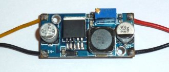
Pulse type stabilizer
The principle of operation of the stabilizer
The operating principle is to maintain the output voltage within specified narrow limits, regardless of the load current and input size.
According to the principles of construction, stabilizing devices are divided into the following groups:
- Parametric;
- Compensatory;
- Pulse.
Parametric stabilizers are based on the use of the current-voltage characteristic of the stabilizing element, where a section with a low differential resistance is selected (when the current changes by a significant amount, the voltage on the element remains constant).
Volt-ampere characteristic of a zener diode
More complex compensation designs use feedback, the magnitude of which is proportional to the difference between the output voltage and the reference voltage.
For your information. Pulse devices are based on the principle of energy storage in a reactive element - capacitance or inductance.
Simple parametric voltage stabilizer
Current stabilizer on a transistor
The simplest design contains only two elements:
- Stabilizing diode – zener diode;
- Current limiting resistor.
This stabilizer circuit has limited use, since it operates in a limited range of load resistance - the current through the zener diode must be at least 3-10 times greater than the load.
Parametric circuit
Voltage stabilizer using a transistor
What is a voltage stabilizer
If you supplement the design with a zener diode with an emitter follower, you will get a parametric stabilizer based on a transistor and a zener diode with better parameters in terms of load current.
In this circuit, the load voltage is determined by the difference between the drop across the zener diode and the base-emitter junction. Stabilization occurs because the potential difference of the base-emitter junction weakly depends on the emitter current.
Turning on the amplification element allows you to increase the load current by a factor of Bst, where Bst is the static transfer coefficient. Using a composite element (Darlington circuit), the permissible load current can be further increased to several amperes.
Darlington circuit
The parametric voltage stabilizer circuit on a transistor has disadvantages. Some voltage instability at the base-emitter junction worsens the stabilization coefficient of the design as a whole. Reducing the load power below a certain minimum causes the output voltage to increase (for silicon components by 0.6 Volts as the base current becomes zero).
Ways to reduce transistor turn-off time
If we have a base resistor and we control the transistor from the microcontroller output with a power supply of 3.3 V, then it turns out that we turn on the transistor with a current of 3.3 V, and turn off the transistor with a current through the same resistor, but with a current of 0.7 V, that is, the base current is turning off the transistor will be less.
Figure 4. Transistor turn-off time 1200 nsec
This is one of the reasons why the transistor turns off more slowly. To increase the turn-off speed of the transistor, we can use the following circuit.
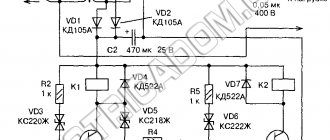
Figure 5. Transistor turn-off time 400 nsec
In the circuit in Figure 5, when turned off, when the output signal from the microcontroller becomes equal to 0 V, it turns out that both resistors 300 Ohms and 200 Ohms are connected in parallel and the total resistance becomes smaller, which leads to an increase in the base current of the transistor when turned off. This increases the turn-off speed of the transistor.
Another way to increase the turn-off speed of a transistor is to reduce the saturation depth of the transistor when turned on. A diode connected from the base to the collector will reduce the saturation depth. At the beginning of switching on, there is a high voltage on the collector, the diode is closed and all the base resistor current flows through the emitter junction of the transistor. When the collector voltage drops below the base voltage, this diode will begin to shunt the emitter junction and part of the base resistor current will flow through the diode, while the current through the emitter junction will decrease and this will reduce the saturation depth of the transistor.
Figure 6. Transistor turn-off delay is about 20 nsec
Principles for calculating characteristics
Parametric voltage stabilizer
For the simplest calculation of characteristics, the following data is required:
- Supply voltage;
- Load current;
- Output voltage.
Calculation procedure:
- Based on the output parameters, the type of stabilizing element is determined;
- The key element is selected according to the following criteria:
- Stabilization coefficient Вst≥In/Ist;
- The permissible collector-emitter voltage is greater than the maximum input voltage;
- The maximum collector current must be greater than the load.
Compensating stabilizers
In compensation stabilizers, the reference (reference) potential is compared with the output potential. The difference, through a negative feedback loop, goes to the base of the key transistor, controlling the amount of its opening.
The accuracy of stabilization depends on the accuracy of the reference voltage formation. Since the comparison device consumes low current, the reference potential can be formed using a parametric stabilizer using a zener diode and a resistor.
Compensation scheme
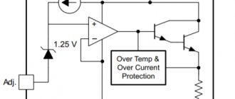
Performance can be further improved by using a current source instead of a current limiting resistor. It is most convenient to use a field-effect transistor as such a source. Compensation devices have good characteristics, so most manufacturers of element base produce ready-made modules that allow you to create structures with a minimum of elements.
Main technical characteristics of LM338
Simple regulated power supply
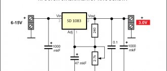
The first diagram is a typical connection of the LM338 trim. The circuit provides an adjustable output voltage from 1.25 to the maximum supplied input voltage, which should not be more than 35 volts.
Variable resistor R1 is used to smoothly regulate the output voltage.
Simple 5 Amp Regulated Power Supply
This circuit produces an output voltage that can be equal to the input voltage, but the current varies well and cannot exceed 5 amperes. Resistor R1 is precisely selected to maintain a safe 5 amp limiting current limit that can be drawn from the circuit.
Regulated 15 amp power supply
As mentioned earlier, the LM 338 microcircuit alone can handle only 5A maximum, however, if it is necessary to obtain a higher output current, in the region of 15 amperes, then the connection diagram can be modified as follows:
In this case, three LM338 are used to provide high current load with the ability to regulate the output voltage.
Variable resistor R8 is designed for smooth adjustment of the output voltage
Digitally controlled power supply
In the previous power supply circuit, a variable resistor was used to regulate the voltage. The circuit below allows you to obtain the required output voltage levels using a digital signal supplied to the bases of the transistors.
The value of each resistance in the transistor collector circuit is selected in accordance with the required output voltage.
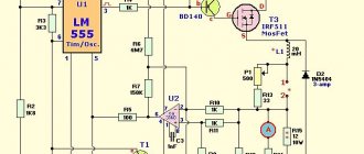
Lighting controller circuit
In addition to power supply, the LM338 IC can also be used as a light controller. The circuit shows a very simple design where a phototransistor replaces a resistor, which is used as a component to regulate the output voltage.
The lamp, the illumination of which must be kept at a stable level, is powered by the output of LM338. Its light falls on the phototransistor. When the illumination increases, the resistance of the photoresistor drops and the output voltage decreases, and this in turn reduces the brightness of the lamp, maintaining it at a stable level.
12V charger for LM338
The following circuit can be used to charge 12 volt lead acid batteries. The RS resistor can be used to set the required charging current for a specific battery.
Smooth switching circuit (soft start) of the power supply
Some sensitive electronic circuits require soft power switching. Adding capacitor C1 to the circuit makes it possible to smoothly increase the output voltage to the set maximum level.
Thermostat circuit for LM338
The LM338 can also be configured to maintain the heater temperature at a certain level.
Here another important element has been added to the circuit - the LM334 temperature sensor. It is used as a sensor which is connected between adj LM338 and ground. If the heat from the source increases above a predetermined threshold, the resistance of the sensor decreases and accordingly the output voltage of the LM338 decreases, subsequently reducing the voltage across the heating element.
Information taken from joyta.ru
Buy Adjustable Voltage Stabilizers LM338 for $2.65
Switching stabilizers
The use of simple designs on transistors has a disadvantage - a large dissipation power is released on the key element, which is greater, the greater the difference between the input and output parameters.
The main difference between pulsed devices is that transistors operate in switch mode, controlling the accumulation and release of energy by reactive elements. The energy stored by a choke or capacitor allows not only to stabilize the voltage, but also to increase it or invert the polarity.
Pulse converters assembled on discrete elements are difficult to design and adjust. Nowadays circuits are produced in the form of integrated circuits, which require a switch only to increase power. The devices require virtually no adjustment and are highly reliable.
Pulse device chip
Stabilized regulated power supply with overload protection
Many amateur radio power supplies (PS) are made on KR142EN12, KR142EN22A, KR142EN24, etc. microcircuits. The lower limit of adjustment of these microcircuits is 1.2...1.3 V, but sometimes a voltage of 0.5...1 V is necessary. The author offers several technical power supply solutions based on these microcircuits.
The integrated circuit (IC) KR142EN12A (Fig. 1) is an adjustable voltage stabilizer of the compensation type in the KT-28-2 package, which allows you to power devices with a current of up to 1.5 A in the voltage range 1.2...37 V. This integrated stabilizer has thermally stable current protection and output short circuit protection.
Fig.1. IC KR142EN12A
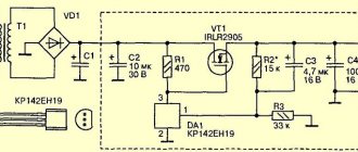
Based on the KR142EN12A IC, you can build an adjustable power supply, the circuit of which (without a transformer and diode bridge) is shown in Fig. 2. The rectified input voltage is supplied from the diode bridge to capacitor C1. Transistor VT2 and chip DA1 should be located on the radiator. Heat sink flange DA1 is electrically connected to pin 2, so if DA1 and transistor VD2 are located on the same radiator, then they need to be isolated from each other. In the author's version, DA1 is installed on a separate small radiator, which is not galvanically connected to the radiator and transistor VT2.
Fig.2. Adjustable power supply on IC KR142EN12A
Composite transistor circuit
A parametric voltage stabilizer on a transistor limits the load current not only due to the permissible current of the key element. Long before the moment of the limiting mode, stabilization deteriorates, since it is limited by the static transfer coefficient of the key transistor.
The load current can be increased by using components connected according to the Darlington circuit. In such a connection, the total transmission coefficient is equal to the products of the coefficients of both transistors. Power amplifier Darlington transistors are often produced in a single package, without requiring additional connections.
Transistor and Zener diode circuit
Connecting a key element to a simple zener diode device allows you to increase the load current with minimal difficulty. The use of a field-effect transistor instead of a bipolar one makes it possible to reduce power dissipation and reduce the drop at semiconductor junctions, thus increasing the efficiency of the design.
Important! When using FETs, the hand and tool must be grounded.
Which voltage stabilizer to choose depends on the requirements for the load current value, stabilization coefficient, and design dimensions.
This largely depends on personal preference. Compensation and parametric devices are easy to understand, easy to assemble and configure. Pulse devices are more technically complex. Although there are many off-the-shelf switching regulator ICs available, lack of a clear understanding of their operation can make troubleshooting difficult. A design selected with a certain current reserve can stand under load for an unlimited time.
Standard Zener Voltages
Zener diodes are available for sale with characteristic voltages ranging from just over 1 V to several hundred volts. For each voltage setting, one or more power ratings are typically available, ranging from just under 0.5 W to over 5 W. Among the most common Zener diode families are the low-power BZX55 series, with VZ voltages from 2.4 V to 75 V and maximum power dissipation up to 500 mW. The BZX85 family of power zener diodes are also widely used with VZ voltages from 2.7 to 100 V and maximum power dissipation up to 1300 mW. There is no point in talking about the domestic D814 and D815, since they have already left the amateur radio scene.