Voltage conversion is necessary in order to realize the possibility of operating various devices from an alternating current network. In addition, powering electronic circuits with different voltages forces not only the conversion of alternating electricity into direct electricity, but also an increase or decrease in the potential difference to the required parameters.
Switching voltage converter
Pulse Conversion Basics
The operation of such devices, also called switching stabilizers (IS), is based on key stabilization. The circuit contains an element that adjusts the output parameters due to its locking and unlocking.
A conventional transformer circuit includes a low-frequency transformer with a primary and secondary winding. Pulse conversion also implies the presence of a transformer, but a high-frequency one.
Attention! High-frequency pulse transformers are smaller in size and cheaper, but their power is higher.
Pulse voltage converters (PVC) allow the use of three types of circuits:
- increasing;
- downward;
- inverter
IPNs have high efficiency and small dimensions. They include the following elements:
- power supply (power supply);
- key – switching element;
- energy storage device of inductive nature – inductor, coil;
- blocking diode;
- output voltage filter – high-capacity capacitor.
The filter is usually connected in parallel with the load.
Advantages and disadvantages
The design of single-phase servo-drive voltage stabilizers has a number of advantages that have brought great popularity to this type of electrical equipment. The increased demand for EMCs encourages many manufacturers to produce various modifications of them. The advantages of this design are as follows:
- high efficiency of the device;
- voltage stabilization accuracy error – 2%;
- no distortion of current output parameters;
- wide range of stabilization of input voltage level deviations;
- the toroidal shape of the transformer coil minimizes the dispersion field;
- the dimensions and large cross-sectional area of the winding wire allow a high load power threshold;
- low cost of stabilizers.
Along with its advantages, EMC has disadvantages:
- Slow response of the servo drive to changes in input voltage. The mechanical drive of the brush assembly is to blame. For example, to smooth out a voltage surge of 50 volts, the device will take about 5 seconds. During this time, sensitive electronics may suffer significant damage.
- The low wear resistance of the brush assembly requires regular replacement of graphite contactors. This factor does not allow EMC to compete with relay and thyristor analogues.
- The operation of the brush assembly with a certain wear of the brushes can cause sparking inside the stabilizers. Therefore, it is strictly forbidden to use it in conditions of high fire danger.
Principle of operation
Voltage stabilizer 12 volts
A switching voltage regulator uses the principle of comparing the reference voltage with the output voltage. The circuit allows you to adjust the duration of the key opening. The input voltage from the power source (PS) is passed by the switch according to the control signal of specified parts (pulses), taking into account that the average potential (lowered or increased) was stable.
IC block diagram
Types of device
The classic electromechanical stabilizer is practically no longer used, but has many advantages. It is distinguished by smooth voltage regulation, which allows you to count on high accuracy of correction of the operating parameters of the electrical circuit. Such models are still used to service sensitive audio equipment and lighting systems. More common is an automatic relay-type voltage stabilizer, the adjustment of which occurs thanks to a mechanical switch.
This option is advisable to use in private houses, country houses and apartments. Digital switching stabilizers are also growing in popularity. The concept of this device fully fits into the concept of modern compact household appliances. Pulse models have displays with a control menu, provide the ability to program the stabilizer function, are characterized by quick adjustment and a high degree of reliability.
Comparison with linear stabilizer
Transistor voltage stabilizer
To compare the two conversion principles, you need to remember that linear stabilizers (LS) are usually a voltage divider. Its unstable potential is supplied to the input of the divider, and the stable potential is removed from the second (lower) arm. The principle of stabilization is to constantly change the resistance of the upper arm of the circuit so that on the lower arm it remains stable.
For your information. When the Uin/Uout ratio is high, the efficiency of the linear stabilizer is very low. This is due to energy losses on the regulating resistor. It heats up, which is why some of the input power is lost.
Such assemblies have their advantages, namely: simplicity of the circuit, a minimum of elements and the absence of interference. Compared to linear ones, switching stabilizers (IS) are more complex, but they work more stable when the circuit is properly selected.
Self-oscillations may occur in the IC, which lead to partial inoperability or complete failure of the converter. This occurs when the source impedance Uin exceeds the value of the IC impedance, then as Uin decreases, the input current increases.
Stabilized power supply 12V/30A
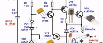
We present a powerful stabilized 12 V power supply. It is built on an LM7812 stabilizer chip and TIP2955 transistors, which provides a current of up to 30 A. Each transistor can provide a current of up to 5 A, respectively, 6 transistors will provide a current of up to 30 A. You can change the number of transistors and get desired current value. The microcircuit produces a current of about 800 mA.
A 1 A fuse is installed at its output to protect against large transient currents. It is necessary to ensure good heat dissipation from transistors and the microcircuit. When the current through the load is large, the power dissipated by each transistor also increases, so that excess heat can cause the transistor to fail.
In this case, a very large radiator or fan will be required for cooling. 100 ohm resistors are used for stability and to prevent saturation as... the gain factors have some scatter for the same type of transistors. The bridge diodes are designed for at least 100 A.
Notes
The most expensive element of the entire design is perhaps the input transformer. Instead, it is possible to use two series-connected car batteries. The voltage at the input of the stabilizer must be a few volts higher than the required output (12V) so that it can maintain a stable output. If a transformer is used, the diodes must be able to withstand a fairly large peak forward current, typically 100A or more.
No more than 1 A will pass through LM 7812, the rest is provided by transistors. Since the circuit is designed for a load of up to 30 A, six transistors are connected in parallel. The power dissipated by each of them is 1/6 of the total load, but it is still necessary to ensure sufficient heat dissipation. Maximum load current will result in maximum dissipation and will require a large heatsink.
To effectively remove heat from the radiator, it may be a good idea to use a fan or water-cooled radiator. If the power supply is loaded to its maximum load, and the power transistors fail, then all the current will pass through the chip, which will lead to a catastrophic result. To prevent breakdown of the microcircuit, there is a 1 A fuse at its output. The 400 MOhm load is for testing only and is not included in the final circuit.
Computations
This diagram is an excellent demonstration of Kirchhoff's laws. The sum of currents entering a node must be equal to the sum of currents leaving this node, and the sum of the voltage drops on all branches of any closed circuit circuit must be equal to zero. In our circuit, the input voltage is 24 volts, of which 4V drops across R7 and 20 V at the input of LM 7812, i.e. 24 -4 -20 = 0. At the output, the total load current is 30A, the regulator supplies 0.866A and 4.855A each 6 transistors: 30 = 6 * 4.855 + 0.866.
The base current is about 138 mA per transistor, to get a collector current of about 4.86A, the DC gain for each transistor must be at least 35.
TIP2955 meets these requirements. The voltage drop across R7 = 100 Ohm at maximum load will be 4V. The power dissipated on it is calculated by the formula P= (4 * 4) / 100, i.e. 0.16 W. It is desirable that this resistor be 0.5 W.
The input current of the microcircuit comes through a resistor in the emitter circuit and the B-E junction of the transistors. Let's apply Kirchhoff's laws once again. The regulator input current consists of 871 mA current flowing through the base circuit and 40.3 mA through R = 100 Ohms. 871.18 = 40.3 + 830. 88. The input current of the stabilizer must always be greater than the output current. We can see that it only consumes about 5 mA and should barely get warm.
Testing and Bugs
During the first test, there is no need to connect the load. First, we measure the output voltage with a voltmeter; it should be 12 volts, or a value not very different. Then we connect a resistance of about 100 Ohms, 3 W as a load. The voltmeter readings should not change. If you do not see 12 V, then, after turning off the power, you should check the correctness of installation and the quality of soldering.
One of the readers received 35 V at the output, instead of the stabilized 12 V. This was caused by a short circuit in the power transistor. If there is a short circuit in any of the transistors, you will have to unsolder all 6 to check the collector-emitter transitions with a multimeter.
Functional diagrams by type of control circuit
Parametric voltage stabilizer
Based on the type of control circuit, several operating circuits can be distinguished, including:
- Schmitt trigger;
- PWM – pulse width modulation;
- PFM – pulse frequency modulation.
Important! Switching regulators are self-regulating devices that rely on a reference voltage to serve as a reference for the regulation circuit.
Block diagrams of IPN with Schmitt trigger and PWM
With Schmitt trigger
With this stabilization circuit design, the upper and lower trigger thresholds are compared with Uin. For this purpose, a comparator is used - a comparison device. The key opens at the moment when the output voltage equals the trigger voltage (Umax). The energy accumulated during this time is supplied to the load, and Uout then decreases. As soon as its value reaches Umin (lower threshold), the trigger switches, closing the switch.
This method is called stabilization with two-position adjustment or relay. Circuits with a Schmitt trigger have voltages at the output of the device with a ripple value determined by the difference in response thresholds. This pulsation is practically impossible to eliminate.
In an IC with a Schmitt trigger, frequency conversion depends on Uin and In (load current) and is variable.
With pulse width modulation
At the output of such circuits, Uav (average) is obtained, which is influenced by the duty cycle of the pulses and Uin. An operational amplifier (op-amp) is a circuit for comparing Uout and Uop (reference) by subtraction and subsequent amplification. The result goes to the modulator, which adjusts its parameters depending on this result.
The modulator changes (increasingly) the ratio of the time at which the key is open to the period of the generator clock pulse if Uout < Uop.
The circuit achieves such a switch control that the difference between Uout and Uop is minimized when Uin or the current through the load (In) changes.
Attention! In ICs with PWM, frequency conversion does not depend on Uin and In.
With pulse frequency modulation
Such assemblies differ in that the duty cycle of the pulses (frequency) directly depends on a decrease in Uin or an increase in In. In this case, the duration of the pulse unlocking the key is unchanged. The pulse frequency is subordinated to the signal of the difference between Uout and Uop. A monostable multivibrator with a controlled trigger frequency can easily cope with sending commands to the switch.
Monostable transistor multivibrator
Basic circuits of the power section
Depending on the purpose of the IS, three basic models of its construction can be distinguished:
- downward;
- increasing;
- inverting.
Regardless of the design and purpose of the IC, devices used as a key can be:
- thyristor;
- transistor (bipolar or field effect).
The main task of such an element is to open or close upon a command received by the control electrode.
Buck Converter
Typically, it is necessary to reduce the voltage more often, which is why such ICs are more in demand.
The simplest step-down IC circuit
For the step-down voltage stabilizer shown in the diagram, the switch on field-effect transistor VT1 will open when control voltage is applied to it. The current from the positive terminal will flow to the load through the smoothing choke L1. The diode VD1 connected in parallel to the circuit does not currently pass current. After opening the key, the current circuit is as follows: inductor L1 – load – common wire – diode VD1 – inductor L1. In this case, the current passing through the inductor will not stop instantly, but will gradually decrease.
Important! For chokes with high inductance, it does not become equal to zero until the next opening of the key. Installation of such elements is impractical due to increased size and cost.
At this time, capacitor C1 will be discharged to the load and maintain U out. Capacitance C, together with inductance L, forms a filter that reduces the ripple range.
Boost converter
Unlike lowering Uin, this type of circuit is used to power load circuits that require a voltage higher than that of the source to operate.
Boosting IP
The circuit components are the same, but included differently. When the transistor is open, the diode is closed, and the current in the inductor increases linearly. When the key is locked, the current begins to move along the circuit: positive terminal - inductor L1 - diode VD1 - load - negative terminal. Capacitor C1 will be charged at this time. It will maintain current on the load while it discharges to it the next time the key is opened.
Inverting converter
Such an assembly also does not have galvanic isolation between the input and output stages. It has a completely different connection of the inductor, capacitor and load. They are located in parallel.
Inverting IC
When the VT1 key is open, current flows through the circuit: positive terminal - transistor - inductor - negative terminal. The choke stores energy with the assistance of a magnetic field. When the transistor closes, the current flow path changes: inductor - capacitor C1 - diode VD1 - inductor. The energy of the inductor and the energy of the capacitor will be completely transferred to the load. The amplitude of the ripple depends entirely on the capacitance C1. At this moment, the voltage across the load does not change, despite the fact that the current through C1 drops almost to zero.
By the way. The output voltage of inverting ICs may differ from the voltage of the power supply, either up or down.
For home
You need to understand that for a home, even an error of 8-10% in relay models is acceptable and most devices “digest” such deviations calmly
Thyristor ones have a higher accuracy of operation, it is usually 3-5%, it would seem, why is this in everyday life? But at the same time, they react faster, as they wrote earlier, and overloads, in the moment, endure much greater ones, and this is important when starting currents of pumps, machines, etc. Well, expensive audio and video equipment gravitates towards good power supply
Example
As an example, let's look at stabilizers from one manufacturer: thyristor Energia Classic and Energia Ultra have an operating accuracy of 5 and 3%, respectively, and tolerate an overload of 180%. Representatives of the Voltron Energy relay segment operate with an accuracy of 5% and are able to withstand a short-term overload of 110%.
Thyristor three-phase stabilizers
Thyristor stabilizers, at the moment, produce only single-phase ones, but for a 380 V network, a modular set of 3 single-phase devices is purchased, and if a device appears that requires exactly 380 V, then a network control unit is purchased.
Effect of diode on efficiency
A diode connected to an electrical circuit causes a voltage drop of 0.4 to 0.7 V. At a current of several amperes and a low Uout, a loss of power occurs on the element, which leads to a decrease in efficiency. An alternative option is used - replacing the diode with a field-effect transistor. Select one so that in the open state the voltage drop across it is minimal.
Attention! Instead of a diode, you can put another switch in the circuits, which will work in antiphase with the main one.
Features of use
Switching stabilizers can be used as drivers for LEDs and LED lamps. In addition, they are used in various devices, such as:
- power supplies for LCD television receivers;
- navigation equipment;
- power supplies for computers and digital system devices.
Switching stabilizers are used for chargers and converting alternating current into direct electricity.
Pulse noise filtering
Strong interference emitted by a pulse voltage stabilizer (VST) at the moment of switching the switch (current and voltage surges) must be suppressed. This requires applying filters and placing them at the input and output.
Input impedance
For ISNs operating under load, as Uin increases, the input current (Iin) decreases. This means its input impedance is negative differential. When connecting the ISN to sources with high internal resistance, unstable operation is possible.
Use in AC networks
To connect to an alternating current source, a rectifier and filter are installed in front of the ISN. This is an area where there is a danger of electric shock to a person. Elements included in this area must be protected from touch or marked with a marker (graphic and color warning).
Do LED bulbs need to be recycled?
LEDs that have lost their consumer properties are classified as waste of the fourth hazard class, that is, they are considered low-hazard. Materials used during the production stage can have a negative impact on the environment and must be recycled.
Hazard class, waste composition and FKKO code
LED lamps are waste of hazard class IV. Enterprises engaged in the production of lighting equipment are required to carry out their certification. This is described in detail in Russian Government Decree No. 712, issued on September 16, 2013.
Additional information: According to the Federal Classification of Municipal Waste (FKKO), LEDs are designated with the code 4 82 415 01 52 4.
Any LED lamp is multi-component. It consists of:
- base elements;
- aluminum body parts;
- polycarbonate;
- plastic.
All these components must be recycled or used in secondary production after recycling. No chemicals are used in the disposal or recycling process. Sorting is carried out without the use of personal protective equipment.
What the law says, Rospotrebnadzor requirements
LED lighting devices are manufactured in Russia according to GOST R 54815-2011/1EC/PAS 62612/2009. Often people who use such lamps at home throw them into ordinary garbage containers, which is contrary to the requirements of Rospotrebnadzor.
Before recycling LED lamps, the structure must be disassembled into individual elements and sorted by materials. The rest is taken care of by special processing enterprises.
Administrative responsibility for individual entrepreneurs and organizations
If waste LED lighting devices do not have waste certificates for products of the fourth hazard class, the enterprise bears administrative responsibility. According to the current regulatory framework, the violator is obliged to pay penalties in the amount of up to 250 thousand rubles. In addition, organizations can issue an administrative order to suspend activities for up to three months.
Benefits of OS regulation
IC voltage regulation feedback is an important option for switching regulators. It allows you to maintain a stable voltage at the output of the device, sensitively monitoring surges in voltage and current. The ISN uses broadband feedback (the wider the frequency interval, the lower the ripple level as a result).
The availability of components for constructing ISN on the radio components market makes it possible to assemble any of the pulse stabilizer circuits with your own hands. The use of ready-made stabilizers on integrated circuits (ICs) and switches on field-effect transistors makes the device as compact as possible.
Comments:
Metelkin
The article is good. It should be added that the pulse stabilizer is designed for low current, i.e. There is no way to connect a TV or computer through it, only a light bulb or some kind of cooler.
Romka
Does anyone know the circuit diagram of a stabilizer for an energy-saving light bulb and is it profitable to assemble it yourself? How much cheaper/more expensive is it than buying a new lamp?
Pashka
Which capacitor should be installed in the electricity storage unit for the stabilizer?