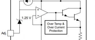
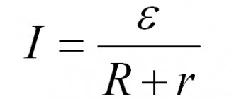
The integrated, adjustable linear voltage regulator LM317 is more suitable than ever for the design of simple, adjustable power supplies for electronic equipment with a variety of output characteristics, both with adjustable output voltage and with a given load voltage and current.
To facilitate the calculation of the required output parameters, there is a specialized LM317 calculator, which can be downloaded from the link at the end of the article along with the LM317 datasheet.
Technical characteristics of the stabilizer LM317:
- Providing output voltage from 1.2 to 37 V.
- Load current up to 1.5 A.
- Availability of protection against possible short circuit.
- Reliable protection of the microcircuit from overheating.
- Output voltage error 0.1%.
This inexpensive integrated circuit is available in TO-220, ISOWATT220, TO-3, and also D2PAK packages.
Purpose of the microcircuit pins:
Powerful pulse current stabilizer
A wide range of supply currents and loads is not always the main requirement for stabilizers. In some cases, decisive importance is given to the high efficiency of the device. This problem is successfully solved by a pulse current stabilizer microcircuit, replacing compensation stabilizers. Devices of this type allow you to create high voltage across the load even in the presence of a low input voltage.
In addition, there is a pulse-type boost current stabilizer. They are used together with loads whose supply voltage exceeds the input voltage of the stabilizing device. Two resistors used in the microcircuit are used as output voltage dividers, with the help of which the input and output voltage alternately decreases or increases.
Online calculator LM317
Below is an online calculator for calculating a voltage stabilizer based on LM317. In the first case, based on the required output voltage and the resistance of resistor R1, resistor R2 is calculated. In the second case, knowing the resistances of both resistors (R1 and R2), you can calculate the voltage at the output of the stabilizer.
For a calculator for calculating the current stabilizer on LM317, see here.
Circuit with two secondary windings of a transformer
The second scheme (Fig. 3) is less common, but is also present. Its difference is that the power transformer has a secondary winding of double the number of turns, with a tap from the middle. This circuit allows you to make a full-wave rectifier using two diodes, instead of four diodes in a circuit with a secondary winding without a tap.
Fig.Z. Rectifier circuit with two secondary windings.
The advantage of this scheme is that it already has a transformer with a double secondary winding. And this allows you to make a good bipolar power supply with a full-wave rectifier. Changes in the circuit are shown in Fig. 4.
We connect a rectifier bridge between the ends of the secondary winding, and take the tap as a neutral wire. Thus, we add another capacitor and two diodes.
Examples of application of the LM317 stabilizer (connection circuits)
Current stabilizer
This current stabilizer can be used in circuits of various battery chargers or regulated power supplies. The standard charger circuit is shown below.
This connection circuit uses a direct current charging method. As can be seen from the diagram, the charge current depends on the resistance of resistor R1. The value of this resistance ranges from 0.8 Ohm to 120 Ohm, which corresponds to a charging current from 10 mA to 1.56 A:
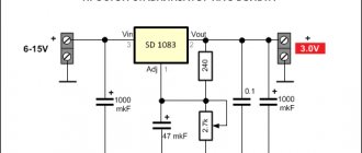
5 Volt power supply with electronic switching
Below is a diagram of a 15 volt power supply with soft start. The required smoothness of switching on the stabilizer is set by the capacitance of capacitor C2:
Adjustable voltage regulator on LM317
Switching circuit with adjustable output voltage
Linear voltage stabilizers based on transistors and integrated circuits.
Online calculation of circuit elements of linear stabilizers with fixed and adjustable output voltage.To maintain stable operation and maintain the declared parameters of electrical equipment, in most cases it must be powered by a constant voltage that is not controlled by any external influences. Typically, this function is assigned to devices called voltage stabilizer . A voltage stabilizer is an electrical energy converter designed to maintain the output voltage level within specified limits when the following quantities change: input voltage, load resistance, and ideally, temperature and other external influences.
Not so long ago, such units were built on zener diodes and transistors, however, with the advent of specialized microcircuits, the need for independent design of such circuits quickly subsided, due to the obvious ease of implementation of stabilizers made on integrated circuits. But in vain!
Where the values of the stabilization coefficient Kst can be calculated in tens rather than hundreds or thousands, the simplest parametric stabilizer not only has the right to exist, but also outperforms its integral counterparts in such an important parameter as the purity of the output voltage and the absence of impulse noise at the moment of a sharp changes in load current. Let's look at these simplest voltage stabilizer devices.
Fig.1 a) The simplest circuit b) With an emitter follower c) With an adjustable output. voltage
The voltage stabilizer circuit shown in Fig. 1 a) is used mainly with devices through which significant currents do not flow. The value of the current Iin flowing both through the zener diode and through the load depends on the value of the resistor Rst. The magnitude of this current is calculated by the formula: Rst = (Uin - Ust)/ Iin , and Iin must satisfy the condition Iin ≥ In. max + Ist. min , where In. max is the maximum current in the load at a given output voltage, and Ist. min - the minimum stabilization current of the zener diode, specified in the characteristics of the semiconductor. In zener diodes of domestic manufacturers, the parameter Ist. min , as a rule, is specified explicitly; for foreign ones it may not be specified at all. Where should a poor Jew go? In this case, I would recommend focusing on the current value from the “Izk” datasheets (the value at which the zener diode has maximum impedance) and increasing this value by 2…3 times. Although, by and large, the optimal (from the point of view of achieving maximum parameters) current for a zener diode is the test current, at which the main characteristics of the semiconductor are measured.
For the zener diode to perform its tasks most efficiently, it is quite important that the load power does not exceed the power dissipated by the semiconductor. Therefore, if there is a need to stabilize the voltage in loads that consume significant power, an additional current amplifier is used - an emitter follower (Fig. 1 b)). In this case, the load for the zener diode is the input resistance of the repeater Rin ≈ Rн x (1 + β) , i.e. the load current can be increased by β times. Here it is important to take into account the voltage drop at the emitter junction of the transistor, and therefore the voltage at the output of the stabilizer will be 0.6...0.7 V (1.2...1.4 V for a composite transistor) less than the stabilization voltage of the zener diode .
By installing a variable resistor in parallel with the zener diode (Fig. 1c)), it becomes possible to change the stabilization voltage in the load from zero to almost the maximum value of the zener diode stabilization voltage (minus the voltage drop Ube at the transistor junction). Naturally, the current flowing through the variable must also be taken into account, setting its value - no less than the input current of the emitter follower. Let's spice up the material covered with a calculator.
TABLE OF CALCULATION OF LINEAR VOLTAGE STABILIZER ELEMENTS
Compensating linear stabilizer circuits are the basis of most integrated circuits that perform the function of stabilizing voltages and currents, and in their simplest form can be made using a zener diode and a pair of transistors (Fig. 2).
Fig.2 Circuits of compensation linear voltage stabilizers
Here the zener diode is a source of reference voltage, and transistor T2 is a device for comparing the output voltage supplied through a resistive divider to its base with the reference voltage at its emitter. The output voltage has increased, and along with it the voltage at the base of T2, the transistor opens slightly and attracts the voltage at the base of the regulating transistor T1 to the negative (ground) bus, thereby reducing the voltage at its emitter, and accordingly at the output of the circuit. The output voltage has decreased - everything is the same, only in reverse. Compensation stabilizers based on transistors have a higher stabilization coefficient compared to the devices presented in Fig. 1, but due to the presence of feedback they also have their drawbacks. In this regard, we will not dwell on them in detail, but will move directly to integrated stabilizers, which have a similar principle of operation, but are much more complex in structure, have higher characteristics and at the same time are very simple and easy to implement.
There are two types of such integrated circuits: adjustable voltage regulators and stabilizers with a fixed output voltage. In the second case, the stabilizer circuit takes on an indecently primitive appearance, unworthy of any serious discussion. In the case of regulators with adjustable output voltage, the circuit is still quite simple, but requires some mental manipulation associated with calculating the resistive divider to obtain the required output voltage.
A typical connection diagram for most adjustable microcircuits is shown in Fig. 3.
Fig.3
The formula for calculating the output voltage is Vout = Vref x (1+R2/R1) + Iadj x R2 , and the resistance value R1 is usually set by the chip manufacturer to achieve the best output characteristics.
To reduce pulsations, some fighters place additional electrolytes of significant quantities in parallel with resistor R2. Of course, these heroes are fighters, but why break the chairs? Any sudden increase in load current, leading to a decrease in the output voltage, will not be able to be processed immediately by the automatic adjustment circuit due to the delay in the feedback circuit caused by this capacitor, and this will significantly reduce the performance of the device. And if for static loads the speed parameter of the stabilizer on the drum, then for dynamic ones (for example, such as ULF) it is very important. Therefore, either these electrolytes are not needed at all, or (if Datasheet strongly recommends them) install small capacitors in strict accordance with the manufacturer’s recommendations.
To begin with, here is a reference table with the main technical characteristics of the most commonly used integrated stabilizers with output voltage regulation.
Type
| U input max V | I out max A | I out min mA | U out min V | U out max V | |
| KR142EN11 | -40 | 1,5 | 10 | -1,2 | -37 |
| KR142EN12 | 40 | 1,5 | 10 | 1,2 | 37 |
| KR142EN18 | -40 | 1,5 | 10 | -1,2 | -37 |
| KR142EN22 | 35 | 5 | 10 | 1,25 | 34 |
| KR142EN22A | 35 | 7,5 | 10 | 1,25 | 34 |
| KR142EN22B | 35 | 10 | 10 | 1,25 | 34 |
| LT1083 | 35 | 7,5 | 10 | 1,2 | 34 |
| LT1084 | 35 | 5 | 10 | 1,2 | 34 |
| LT1085 | 35 | 3 | 10 | 1,2 | 34 |
| LM117 | 40 | 1,5 | 5 | 1,2 | 37 |
| LM137 | -40 | 1,5 | 10 | -1,2 | -37 |
| LM138 | 35 | 5 | 10 | 1,2 | 32 |
| LM150 | 35 | 5 | 10 | 1,2 | 33 |
| LM217 | 40 | 1,5 | 5 | 1,2 | 37 |
| LM317 | 40 | 1,5 | 5 | 1,2 | 37 |
| LM317LZ | 40 | 0,1 | 5 | 1,2 | 37 |
| LM337 | -40 | 1,5 | 10 | -1,2 | -37 |
| LM337LZ | -40 | 0,1 | 10 | -1,2 | -37 |
| LM338 | 35 | 5 | 10 | 1,2 | 32 |
| LM350 | 35 | 3 | 10 | 1,2 | 33 |
| TL783 | 126 | 0,7 | 0,1 | 1,25 | 125 |
The table below allows you to calculate the values of divider resistors for some popular types of adjustable stabilizer microcircuits presented by different manufacturers.
TABLE OF CALCULATION OF ELEMENTS OF MICROCIRCUITS - VOLTAGE STABILIZERS
| Output voltage Uout (V) |
| Resistance R1 (Ohm) |
| Resistance R2 (Ohm) |
| Maximum permissible input voltage (V) |
| Maximum load current (A) |
| Comments for input errors |
If you don’t want a sudden “powerful fart” to be heard, pay attention to the polarity of capacitor C2.
It must match the polarity of the input (output) voltage. Separately, I would like to dwell on MICRO-POWER STABILIZERS WITH LOW CONSUMPTION.
Stabilizers of this kind will not be at all superfluous in the household, since they will be able to provide such an important indicator of electronic equipment with autonomous power supply as the efficiency of its components.
Here the choice of integrated circuits is noticeably poorer, and the prices, as a rule, are noticeably higher than for analogues with standard consumption, so I will start with a simple, but time-tested circuit using discrete elements.
Fig.2
What is good about KT315 in this inclusion? At the reverse-biased junction KT315 at a voltage of 6 - 7.5V, depending on the type of transistor, an electrical (I’m not afraid of this word) breakdown occurs, which allows it to be used as a zener diode for the same breakdown voltage value. Moreover, a transistor in this connection, unlike many industrial zener diodes, works well at low stabilization currents, about 100 μA.
Of the relatively affordable integrated stabilizers with low internal consumption, I can recommend LP2950, LP2951, LM2931, LM2936 and the like.
lm317 calculator
To simplify the calculation of the resistor value, you can use a simple calculator that will help calculate the required values not only for LM317, but also for L200, zener diode TL431, M5237, 78xx.
(319.9 KiB, downloads: 50,534)
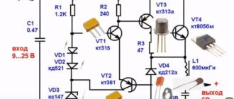
Update from 02.25.16
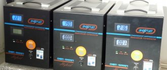
For example, you got your hands on a power supply from a router with a “change” of 9-12 volts at the output. If the dimensions allow, then why not build a stabilizer inside?
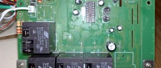
The body must be carefully split along the seam using a knife and a tangible tap on the knife. All the electronics can be done on the board, but I didn’t bother and soldered it “over the top”, using hot glue here and there. LED - optional. The halves are glued back together with superglue.
Sometimes you have to replace the plug. The most common are 5.5/2.1 mm (outer/inner diameter) and 5.5/2.5 mm.
If possible, it is better to take those on the right with a yellow insulator. They are not made so poorly.