Surge Protectors - These are electronic devices with a complex structure, which means they have different functionality and possible malfunctions. There are various incidents in their work that are associated with the greatest loads, and there are also real breakdowns. These concepts should be distinguished, for which there are several tips.
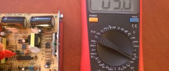
First of all, let's look at how you can perform a quality check of the operation of this device. The most reliable method of monitoring the quality of a device is a conventional voltmeter, which can measure the voltage in the apartment network, as well as the voltage at the output of the device. In a home outlet, the voltage can fluctuate in the range of 170-240 volts, and at the output of the stabilizing device it should be equal to 220 volts.
But not everyone uses a simple method of checking the operation of a voltage stabilizer, since they trust the data from the indicator. But this trust is not always justified, and sometimes on Chinese devices the digital indicator is simply connected directly to the relay. In this case, the relays have a fairly large step, and it will always show 220 V. In fact, the output will have a completely different value.
How to check all voltage stabilizing devices with a multimeter
Voltage stabilizers are electronic devices with a complex structure, which means they have different operating problems and possible malfunctions.
There are various incidents in their work that are associated with the greatest loads, and there are also real breakdowns. These concepts should be distinguished, for which there are several tips. First of all, let's look at how you can perform a quality check of the operation of this device. The most reliable method of monitoring the quality of a device is a conventional voltmeter, which can measure the voltage in the apartment network, as well as the voltage at the output of the device. In a home outlet, the voltage can fluctuate in the range of 170-240 volts, and at the output of the stabilizing device it should be equal to 220 volts.
But not everyone uses a simple method of checking the operation of a voltage stabilizer, since they trust the data from the indicator. But this trust is not always justified, and sometimes on Chinese devices the digital indicator is simply connected directly to the relay. In this case, the relays have a fairly large step, and it will always show 220 V. In fact, the output will have a completely different value.
How to check a zener diode: with a tester, on the board
Many people are faced with the problem of frequent power outages, network overloads and short circuits, as a result of which expensive equipment in the house breaks down. To solve the problem, install a voltage stabilizer or zener diode. What is the device, what is the principle of its operation, what is its scope of application and how to check the zener diode? More on this and more below.
Device Description
A voltage stabilizer is considered a switching device, the main purpose of which is to protect the network from large amounts of electricity generated due to short circuits and overloads. This device is switched on and off from the electrical circuit. Equipped with a magnetic type of release or electromagnetic. Its main advantage is the fact that it allows you to protect an electrical installation or transformer substation from overvoltage, network overload and breakdown as a result of frequent network outages.
Definition of a stabilizer from a reference book
Purpose of inspection
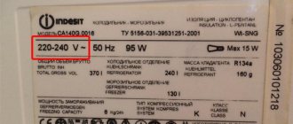
Voltage stabilizer is a device used as an input device. It is placed in front of the counter. Used in networks with one, two and three phases. Can be used for one electrical appliance with a power of more than 6 kilowatts. Three-pole can be used for equipment over 9 kilowatts.
Most often it is used to protect household electrical or heating appliances. It can also be used to protect lighting system, motor, transformer and industrial electronic appliances.
Note! It is necessary to check the voltage stabilizer so that it can work properly and help the user protect the electrical circuit from overvoltage, short circuit and other troubles. This must be done, since sometimes the stabilizer itself can cause damage to the electrical circuit and all household equipment.
Checking the functionality of the circuit protection device
Zener diode capacity
As a rule, information about how many volts the zener diode has is indicated on the body of the device itself. This data is also indicated in the technical documentation. If there is no inscription or documentation, there is a third option on how to find out how many volts the zener diode is - look for this information on the Internet. Older models can be found in online directories. Foreign models have simpler markings than their Russian counterparts. All information is reflected on the device body under the letter V.
You might be interested in this Features of branch compression Inscription with the number of volts in the device
How to check the electrical stabilizer
This check is quite simple. To do this you need to take the following devices:
- Two table lamps.
- Stabilizer.
- Electric stove.
- Power extension cord with 3 sockets.
- Insert the extension cord plug into a household outlet.
- Connect the stabilizer to an extension cord.
- Connect a 60 W table lamp to the stabilizer.
- Connect the electric hotplate to the extension cord.
If the stabilizer functions normally, then the operation of the tile will not affect the light of the light bulb, but if the lamp is connected directly to the extension cord, then when the tile is turned on, the light will become weaker. This is explained by the fact that a powerful consumer in the form of a tile significantly reduces the voltage and the lamp connected to the network before the device will produce less light. But a lamp powered after a voltage stabilizer will not respond to increased load.
It also happens that people do not understand the work of the stabilizer and complain about its poor performance, although this is not the case at all. This happens in such a way that the stabilizer de-energizes the load unexpectedly when washing clothes in an automatic machine. But there is no fault with this. An automatic washing machine is a powerful consumer of electrical energy, but its power is distributed unevenly. When heating water, the power can reach up to 5 kW, and during normal washing it decreases to 2 kW. From high school physics lessons we know that if you reduce the voltage at the input of a transformer and increase the voltage at the output, the output power will also decrease significantly. See the article about a stabilizer for a washing machine.
Tester for zener diodes
Checking zener diodes with a multimeter does not provide a 100% guarantee of their serviceability. This is due to the fact that it cannot check its basic parameters. Therefore, many radio amateurs make a zener diode tester with their own hands.
The circuit of the simplest version consists of a set of batteries, a fixed resistor with a nominal value of 200 Ohms, a variable resistance of 2 kOhms and a multimeter.
The batteries are connected in series to obtain the potential necessary for measuring the parameters of the zener diodes. Stabilization voltages generally lie in the range of 1.8-16 V.
Therefore, an 18 V battery is assembled. Then, to its terminals, we connect in parallel a series chain of a 2 kOhm variable resistor with a power of 5 W and a constant 200 Ohm resistor.
The second will play the role of limiting resistance. The leads of the variable resistor are connected to a three-pin terminal block.
The first contact is connected to the terminal connected to the positive of the battery, the second is the other extreme terminal, and the third is the middle movable contact of the resistor.
In other versions of testers, switching power supplies with adjustable voltage of the output stage can be used, but the essence does not change; the meter remains a multimeter.
Check procedure
The whole process comes down to how the diodes are tested. This is done with a conventional multimeter in resistance or diode testing mode. A working zener diode can conduct current in one direction, similar to a diode.
Let's consider an example of checking two zener diodes KS191U and D814A, one of them is faulty.
First we check the D814A diode. In this case, a zener diode, by analogy with a diode, passes current in one direction.
Now we check the KS191U zener diode. It is obviously faulty, since it cannot pass current at all.
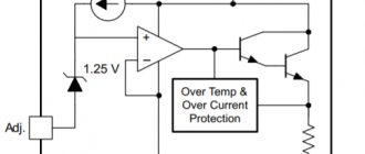
How does this element work?
Both externally and in terms of the implementation of the pn junction, this element is similar to a semiconductor diode. Even the schematic designation is not much different.
Current also flows through it in one direction, but there is one peculiarity. The diode organizes the movement of particles only from the anode to the cathode; the passage of reverse current is an emergency: that is, a breakdown of the radio element.
In a zener diode, reverse current is a normal situation; it is this feature that determines its purpose. When a certain voltage value appears at its terminals, the movement of electrons in the direction from the cathode to the anode opens, and the element becomes reverse conductive.
Moreover, this voltage is the main characteristic: for example, a 12-volt zener diode, when this value is reached, begins to pass current in the opposite direction.
Let's look at this phenomenon using a simple example.
Let's say we have a water vessel with a drain pipe at a certain level.
When the liquid reaches the required height, an overflow occurs from the drain pipe. That is, the vessel will be filled only to a certain value, which will remain stable up to a certain pressure. If the flow of water exceeds the capacity of the drain pipe, the vessel will overflow or burst.
Let's translate the situation into electronics.
- water pressure is the maximum current that the zener diode is designed for without electrical (thermal) destruction;
- the required level is the response voltage of the zener diode.
When the specified voltage is reached, it is fixed, and the “extra” current moves in the opposite direction. Thus, the element stabilizes the voltage. If the current is too high, the zener diode will burn out.
The main purpose of determining performance is to check the zener diode for stabilization voltage.
Checking the stabilizer chip
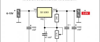
It is required to assemble stabilizing circuits to power the device on the PIC 16F 628 microcontroller, which normally operates from 5 V. To do this, we take the PJ 7805 microcircuit, and on its basis we carry out the assembly according to the diagram from the datasheet. Voltage is applied, and the output is 4.9 V. This is enough, but stubbornness takes over.
We took out a box with integral stabilizers, and we will measure their parameters. To avoid making mistakes, we put the diagram in front of us. But when checking the microcircuit, it turned out that the output is only 4.86 V. Here we need some kind of probe, which is what we’ll do.
Using a battery and a light bulb
There is an option to test a triac with a simple tester, which is an open single-line circuit with a power source and a test lamp. You will also need an additional power source for testing. Any battery can be used as it, for example type AA with a voltage of 1.5 V.
The details must be called in a certain order. First of all, it is necessary to connect the contacts of the tester with the working contacts of the triac. The control lamp should not light up.
Then it is necessary to apply voltage between the control and working electrodes from an additional power source. The working electrode is supplied with a polarity corresponding to the polarity of the connected tester. When connected, the indicator lamp should light up. If the triac transition is configured for the appropriate holding current, then the lamp should light even when the additional power source is disconnected from the control electrode until the tester is turned off.
Probe circuit for checking the KREN microcircuit
This scheme is inferior to the previous layout.
Capacitor C1 removes generation when the input voltage is connected in steps, and capacitor C2 is designed to protect against impulse noise. We take its value to be 100 microfarads, the voltage according to the value of the voltage stabilizer. The 1N 4148 diode prevents the capacitor from discharging. The input voltage of the stabilizer must exceed the output voltage by 2.5 V. The load should be selected in accordance with the stabilizer being tested.
The rest of the probe elements look like this:
The contact pads became the mounting location for circuit elements. The body turned out to be compact.
A power button was installed on the case for ease of use. The pin contact had to be modified by bending.
At this point the sampler is ready. It is a kind of attachment to a multimeter. We insert the probe pins into the sockets, set the measurement limit to 20 V, connect the wires to the power supply, adjust the voltage to 15 V and press the power button on the probe. The device worked, the screen displays 9.91 volts.
Methods for testing power supplies and stabilizers
This section provides basic testing methods used for all types of power supplies and stabilizers, both very simple and more complex. If the circuit successfully passes all the tests described in the book, then it is completely suitable for use. If the test results do not meet standard requirements, they can serve as a basis for determining the cause of the malfunction.
Testing methodology
The main function of any autonomous power source is to convert alternating current into direct current. In DC-DC converters it is converted into a similar one, but with a different voltage (usually higher, but sometimes lower). The functionality of the power supply is checked by measuring the output voltage. Naturally, for a more detailed check of the power source, it should be measured with load, no load, and also with partial load.
If the output voltage of the power supply at full load corresponds to that specified in the data sheet, then its main function is performed. However, as experience shows, it is useful to additionally check the stabilization coefficient
power supply voltage, internal resistance and output voltage ripple amplitude.
Checking the output voltage
In Fig. 7.1 shows a schematic diagram of checking the power source. The circuit provides for testing the power supply with no load, half load and full load (depending on the position of the Sl switch). When switch Sl is in position 1, no load is connected to the power supply output. In positions 2 and 3, a load is connected equal to half and the full rated load of the power source, respectively.
Rice. 7.1. Basic power supply test circuit
To calculate the value of load resistance R1 or R2, which is determined by the output voltage E and the maximum (or half) value of the load current I, you must use Ohm’s law: R – E / I. For example, if the power source is designed for an output voltage of 5 V and a current of 500 mA (0.5 A), then the value of R2 = 5 / 0.5 = 10 Ohms (full rated load). For a load equal to half the rated load, R1 = 5 / 0.25 = 20 Ohms.
If it is necessary to test several power sources, it is advisable to have a variable load, the value of which is selected based on the conditions for testing the power source; The load resistance value is measured in advance with an ohmmeter. Resistors must not have an inductive component to the impedance (wound-wound resistors cannot be used) and must have sufficient power dissipation so as not to overheat. So, if we use the values of Rl and R2 from the previous example, the power dissipated on resistor R1 will be 5 x 0.5 = 2.5 W (that is, a resistor with a dissipation power of at least 5 W should be used), and for R2 the dissipation power will be 5 x 0.25 – 1.25 W (requires a resistor with a dissipation power of 2 W).
To carry out the check you need:
1.Make connections in accordance with the diagram in Fig. 7.1.
2.Set the required values of resistances Rl and R2.
3. Turn on the power source. Set the correct input voltage using its intermediate value (unless otherwise specified). For example, the input voltage for a conventional switching power regulator is 4-20 V. To check the load characteristics and linearity of stabilization, input voltages of 5.8-15 V should be used. When testing DC-DC converters, an autonomous, regulated input voltage source is required. (An example of such a source is shown in Fig. 7.2.) For power supplies made in the form of autonomous units, the required input voltage value can be set using an adjustable autotransformer. When performing a number of tests, a nine-volt battery can be used as a source to set the voltage approximately in the middle of the desired range.
4. Measure the output voltage at each position of switch S1.
5. Then, using Ohm's law, you need to calculate the currents for positions 2 and 3 of switch S1. For example, if R1 = 20 ohms and the voltmeter registers an output voltage of 4.8 V in position 2 of switch S1, the load current will be 4.8 / 20 = 0.24 A, or 240 mA. If the power supply output voltage is 5V in position 1 and drops to 4.8V in switch position 2, the power supply is not maintaining its rated voltage at full load. A decrease in output voltage under load means either poor wiring design (for experimental power supplies) or a malfunction of individual elements (discussed in the troubleshooting section).
Changing Output Load
The change in voltage or current of a regulated power supply with a change in load (sometimes called load effect or output instability) is usually expressed as a percentage and is defined as:
It should be noted that output instability values are generally not very good (i.e., high percentage values) when the power supply's internal resistance is high.
Rice. 7.2. Adjustable self-contained power supply
Note to fig. The input voltage is adjustable from 3.5 to 20 V, the output current varies from zero to 90 mA. Output instability is 02% (load and mains power). The ripple level at full load does not exceed 0.5 mV. T1 – transformer STANC0R-TP3.
Instability of the output voltage caused by instability of the mains supply
Output voltage instability due to changes in line supply voltage (also known as line effect, input instability, source effect) is usually expressed as a percentage change in output voltage and represents the maximum allowable output voltage (for a given load) for the maximum change in input voltage. For example, a power supply is designed to operate from an AC mains voltage of 110-120 V, and the output DC voltage should be equal to 100 V. In the first measurement, the output voltage at the input of the source was equal to 120 V, and in the second, 110 V. If If there is no difference in the output voltage between the two measurements, then its stability with respect to the input voltage is ideal (and most likely unrealistic). If the output voltage changed by 1 V, then relative to 100 V the change was 1%. The actual value of the instability of the input voltage of the power source must be determined at full, half or other load value required by technical conditions. Of course, the input voltage must be changed using a stabilizer or a separate DC source from the minimum to the maximum possible and measured with a device with a high accuracy class.
Internal power supply resistance
The internal resistance of the power supply is determined by the following relationship:
A minimum internal resistance value is preferred because it indicates the minimum change in output voltage when the load changes. The measurements are performed in the following order:
1. Assemble the circuit in accordance with Fig. 7.1.
2. Set the value of resistance R2 required according to the test conditions.
3. Turn on the supply voltage. Measure the output voltage in positions 1 (no load) and 3 (full load) of switch S1.
4. Calculate the actual value of the current in position 3. For example, if the resistance R2 is 10 Ohms, and the output voltage in position 3 of switch S1 is 4.999 V (as in the previous example), then the current value is:
Using the obtained values of the output voltage without load and with full load and the value of the load current, you can determine the internal resistance of the source. So, if the output voltage without load is 5 V, the voltage with full load is 4.999 V and the current is 0.499 A, then the internal resistance will be.
efficiency
Efficiency is usually expressed as a percentage and is the ratio of the power supply's output power to its input power (multiplied by 100 to express the result as a percentage). Although the calculations are very simple, there are some difficulties in determining the input current and measuring the input voltage. If you do not have an ammeter, you must use a resistor connected in series to the input of the power supply to measure the input current. You should then measure the voltage drop across this resistor (in volts) and calculate the current using Ohm's law (I – E/R). When using a resistor with a resistance of 1 ohm, the current value will be expressed in amperes, and with a resistance of 1000 ohms - in milliamps. Although the steady-state input current of most IC switching regulators is small, the initial inrush current upon turn-on can be quite large.
Assuming a full load output voltage of 4.999V with a load current of 15mA and an input voltage of 4.5V with an input current of 20mA, then the input power consumption would be 90mW (4.5 X 0.02) and day off
power – 75 mW. Thus, the efficiency will be 83% (75 / 90). This value is typical for most battery-powered switching regulator circuits.
Output voltage ripple
In any power supply, regardless of the quality of stabilization or filtering, ripple is always present. Battery-powered switching sources also have a small AC component in the output voltage. Ripple (regardless of its origin) can be measured with an oscilloscope or measuring instrument. Typically, the coefficient reflecting the magnitude of ripple is calculated as the ratio between the magnitude of ripple and the total output voltage. For example, if the ripple is 0.03 V and the output voltage is 5 V, then this ratio will be 0.03 / 5 = 0.006 (or 0.006 x 100 - 0.6%).
The measurement procedure is as follows:
1. Assemble the circuit in accordance with Fig. 7.1.
2. Set the value of resistance R2 required according to the test conditions. Ripple measurements are usually made at full (100%) load.
3. Apply voltage. Measure the value of the output DC voltage in position 3 (full load) of switch S1.
4. Set the meter switch to the AC current measurement position. Any instrument readings under these conditions characterize the ripple voltage.
5. Find the value of the ripple coefficient (in percent). It is equal to the ratio of two voltages (alternating ripple voltage and constant output).
6. A significant problem when assessing the magnitude of pulsation using a measuring device may be the difference between the shape of the pulsating signal and the sinusoidal one, since most devices are calibrated to measure exactly the sinusoidal signal. Therefore, a more reliable way to measure ripple is to use an oscilloscope (see Fig. 7.3), through which the amplitude of the peaks can be determined.
7. It is necessary to adjust the oscilloscope sweep to obtain one or two periods of ripple voltage on the screen. It should be remembered that with full-wave rectification two “humps” are formed per period, and one-half-wave rectification produces one “hump”.
Examining the ripple waveform in the following cases helps identify the source of ripple in the power supply circuit:
o npu load imbalance of the rectifier arms (more current flows through one rectifier diode than through the other) the ripples are not equal in amplitude;
o if the source has a high level of noise or fluctuations (especially when using zener diodes), the pulsations are not constant in amplitude and shape;
o if the pulsation frequency changes, then the frequency of the alternating current source is not constant (in switching power supplies the switching frequency varies);
o If half-wave rectification is observed at the input of a full-wave rectifier, then one of the rectifier diodes does not conduct current.
Rice. 7.3. Connection diagram for checking power supply parameters
Detailed check
The basic testing methods described above are sufficient for most cases encountered in amateur practice, although there are many other methods for testing equipment for industrial and research purposes.
In Fig. 7.3 shows a connection diagram for checking the five most important parameters (performance characteristics) of the power supply: the influence of external power, load; harmonic and random distortion (HRDI), drift and temperature coefficients. In addition to those listed, there are a number of additional measurements, in particular noise and transient response time. However, sophisticated equipment is required for these purposes, especially when testing experimental or industrial equipment. For a more detailed study of methods for testing and measuring the characteristics of power supplies, we recommend the book by J. Lenk, “Complete Guide to Electronic Power Supplies,” 1990, Prentice-Hall.
Equipment for performing measurements
To perform the test measurements described in this section, you will need four instruments: a variable autotransformer, a differential or digital AC voltmeter, a conventional AC voltmeter, and an oscilloscope.
Naturally, to test battery-powered sources, you need a regulated DC source (see Fig. 7.2).
Using a separate power supply may cause some problems. The presence of ripple or voltage fluctuations in it can affect the power supply being tested and distort the test results. This situation can be easily corrected by replacing the external power source with a battery with the same voltage. If ripple or other fluctuations persist, the power supply being tested is faulty.
You must ensure that the autotransformer or regulated DC voltage source (for battery-powered sources being tested) is rated to carry sufficient current. Otherwise, the voltage supplied from it to the input of the source being tested may have significant distortion, as a result of which the conditions (and results) of the operation of the rectification or stabilization circuits will differ greatly from the nominal ones.
The measurement accuracy of a DC voltmeter must be up to 1 mV or higher, the sensitivity of the oscilloscope must be at least 100 μV/cm, and the bandwidth must be at least 10 MHz. It is advisable that both the oscilloscope and the voltmeter have a current measuring device (such as a current shunt, preferably with clamps), since in pulsed sources the current waveform on the oscilloscope screen often helps determine the cause of the malfunction (as will be shown below). In switching source circuits, non-electronic types of combination meters (ampere-volt-ohmmeters), such as the classic Simpson 260 or Tripplet 630, can also be useful, since digital and other electronic devices are often affected by the pulsed signals generated in the circuits under test.
Correct connection
To obtain correct results, all connections must be permanent and secure (alligator clips, etc. are not recommended) and must be made to specific source locations. Using wires with clamps at the ends usually leads to measurement errors. In this case, the contact resistance at the clamp contact point is added to the measurement results. The use of clamps even to connect a load may cause measurement errors.
Connection with separate wires
Each measuring device must be connected to the measuring points with a separate pair of wires (see Fig. 7.3). This connection avoids the subtle crosstalk effects that can occur between measuring instruments (unless all of their ground wires are connected to a low-impedance terminal on the power supply). To eliminate the influence of interference, you must use a twisted pair of wires or a shielded cable.
Load resistance
The load resistance must match the capabilities of the source and the test conditions. A correctly selected load resistance ensures that the source operates at the maximum permissible values of output voltage and load current.
Interference and interference, the influence of parasitic connections with the “ground”
It is necessary to carefully check the connections of all connections to avoid possible interference and/or problems due to parasitic connections to the ground (grounding at several points, especially incorrectly selected ones). The simplest way to check is to turn off the source and use an oscilloscope to check for the presence or absence of unwanted signals (especially in the 50/60 Hz power supply frequency range). In this case, the oscilloscope wires must be connected to the output contacts of the source. Then both oscilloscope wires should be connected to the terminal (+ or -) that is connected to ground, or to a common point. If noise is observed during these measurements with the source disconnected, the cause is most likely crosstalk or ground coupling effects.
Connecting an AC Voltmeter
The AC voltmeter should be connected as close as possible to the power supply input terminals. In this case, the measured value is the voltage directly at the input of the source being tested, without possible errors due to the voltage drop in the wires by which the power source is connected to the network. The same applies to measurements made at the input of the battery source. That is, it is necessary to measure the DC input voltage at the input terminals of the source being tested, and not at the output terminals of the adjustable stabilizer or batteries.
Network stabilizers
When testing power supplies or when operating them, do not use network stabilizers, unless this point is specifically stated for this type of power source. This warning is especially important when working with switching power supplies and DC voltage stabilizers. A network stabilizer can introduce significant distortions into the shape of the output signal of a pulsed source and thereby create a constant error in the output voltage.
Power supply influence
This method consists in the fact that measurements of the output voltage are carried out when the input voltage changes within a specified range from the lower limit to the upper one. The check is performed with the remaining values of the remaining parameters unchanged. They must comply with the technical specifications for any range of changes in the output voltage specified in the passport, with the specified
checking the output current values. The limiting values of the parameters for the following tests are, as a rule, the maximum output voltage and the maximum cw load current.
Load effect
These measurements are made by closing and opening switch S1 (Fig. 7.3) and recording changes in the output voltage. The test is carried out with constant values of the remaining parameters, which must correspond to the technical characteristics for any normalized output voltage at given input values. The limiting parameter values for such tests are, as a rule, the maximum output voltage and maximum load current.
Noises and pulsations
In many cases, the term “periodic and random deviations” is replaced by the term “noise and pulsation”. This parameter represents the deviation of the DC output voltage from the average value (within a certain frequency bandwidth) with all other parameters unchanged.
For example, for Hewlett Packard laboratory power supplies, this parameter is measured in RMS or peak-to-peak (peak to peak) voltages with a bandwidth of 2 G to 2 MHz. Fluctuations in the frequency range below 20 Hz are considered to be dray. Peak-to-peak measurements are of particular practical value in applications where noise spikes can be particularly harmful (for example, in digital logic circuits). RMS measurement is ineffective in the case of noise, since the output noise spikes may appear as short-term ripples; in this case, the value of the mean square value increases slightly. When testing periodic and random variations or noise and ripple levels, always use twisted pair wire (for a single beam oscilloscope) or two-wire shielded cable (for a differential oscilloscope).
Drifting
Drift measurements involve observing the output voltage of the power supply using a differential or digital voltmeter over a fixed, long period of time (typically eight hours after a 30-minute pre-warm-up). In some cases, recording devices with continuous recording of measurements are used. During testing, a thermometer must be placed near the power source to ensure that the ambient temperature remains constant. The appliance under test should be located in a location protected from convection air currents (away from open doors, windows or air conditioning vents). If possible, it is better to place it in a thermostat and maintain the set temperature. It should be remembered that with a stabilized power supply with good characteristics, the greatest drift in the output voltage appears during the first 30 minutes of warm-up.
Temperature coefficient
Temperature coefficient is measured by placing the power supply under test in a thermostat and varying the temperature within specified limits (preheating at each fixed point for 30 minutes). Unless otherwise specified, the temperature coefficient is defined as the amount of change in the output voltage of the power supply when the temperature changes by 5 °C. The measuring instrument should be located outside the thermostat and should have high characteristics of both thermal stability and continuous operation stability to ensure that drift in the voltmeter reading will not affect the accuracy of the measurements taken.
Source: Lenk D., 500 practical circuits on popular ICs: Transl. from English – M.: DMK Press, – 44 p.: ill. (Tutorial Series).
Tweet Like
- Previous Post: 100V Output Voltage Source
- Next entry: Digital microphone for teaching birds to sound onomatopoeia
- Load switch of electromechanical alarm clocks (0)
- What is the difference between current and voltage? (2)
- Current and Voltage Relationship (0)
- AUDIO PREAMPLIFIER WITH AGC (2)
- POWER SUPPLY FOR CAR RADIO (0)
- BATTERY ELECTRICAL ISOLATION DEVICE (0)
- BATTERY CHARGER (0)
Related posts:
How to check the electrical stabilizer?
The question of how to check a voltage stabilizer is relevant for many enterprises, organizations and private users. Stabilizing devices are quite complex equipment, the quality of which determines the serviceability of the connected expensive equipment. Therefore, monitoring their performance and timely detection of faults is a necessary condition for ensuring uninterrupted technological processes and minimizing additional costs.
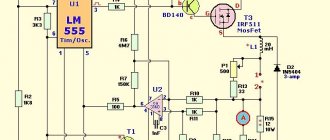
Diagram of a device for testing zener diodes
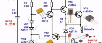
As you can see, the scheme is simple. The voltage from the transformer with two 24V secondary windings is rectified and filtered to obtain a constant voltage of about 80V, then goes to a voltage stabilizer formed by the elements (R1, R2, D1, D2 and Q1), which reduces the voltage to 52V to avoid exceeding the maximum operating voltage limit of the LM317AHV .
Pay attention to the letter index of the microcircuit. For LM317AHV, the input voltage, unlike LM317T , can reach a maximum of 57V.
Stabilizer malfunctions
The most important characteristics of stabilizers that are subject to control are the rated input and output voltage, load current, degree of stabilization, ripple value, and temperature of internal components. To fully diagnose these parameters, special equipment is required. Testing devices using triac switches is considered especially difficult. It requires precise circuitry and specialized measuring instruments, including an oscilloscope.
Let's look at some common problems with stabilizers:
- In relay devices, most often the relays that are responsible for switching the transformer windings fail. Also sometimes the coil burns out.
- The transformer overheats without a serious load. This problem occurs due to turn-to-turn short circuit or short circuit in the switches.
- Overheating of the servo stabilizer. It can occur due to the short circuit of adjacent turns due to contamination of the contact pads. To prevent this, devices must be periodically disassembled and cleaned.
- Burnout of one of the electronic components. It can occur due to short circuits, overloads, or excessively high temperatures.
Diagram of the simplest method for checking zener diode voltage
Radio amateurs and all those who are good friends with electronics know that the task of finding a zener diode with the required characteristics (operating voltage) is boring and painstaking. It happens that you need to go through a lot of different instances until you find the desired Vz value. Checking the status of the zener diode is usually done using a regular multimeter diode scale, this test gives us an accurate idea of the condition of the component, but does not allow us to determine the Vz value. In general, a zener diode tester is a really convenient device when we want to quickly find out the value of the voltage Vz.
How to check the electrical stabilizer?
To troubleshoot the device, you need to do the following:
- Preliminary check. It can be carried out without special devices. To do this, you will need two table lamps of the same power, an electric stove or other powerful consumer, and a power extension cord with several sockets. We connect a stabilizer, one light bulb and an electric stove to the extension cord. We power the second light bulb from the stabilizer. Turn on the tile. If the stabilizer works correctly, then the light of the lamp connected to it will not change, but the light of the lamp connected to the extension cord will decrease.
- Disassembling the equipment, thoroughly removing all contaminants, cleaning the contact pads to a metallic shine.
- Inspection of the stabilizer, identification of electronic components with traces of exposure to high temperature. Overheated resistors look charred, and blackening and cracks may appear on the transistors. You also need to pay attention to swollen capacitors. Another symptom of overheating is a change in the shade of the textolite board.
- Ringing of power switches and other components.
Is it possible to check the zener diode without desoldering?
Yes, this is possible, but not all modes of the radio element are tested. The zener diode always has electrical connections with the rest of the circuit elements, so it is impossible to check it for breakdown as part of the product.
You can check the zener diode with a multimeter on the board only for the stability of the supply voltage. To do this, you need to turn on the electrical device and connect the tester probes to the legs of the part.
Naturally, you should know the original value from the labeling. In this case, it is necessary to measure the voltage at the input and after the stabilizer. If the value at the input is higher than or equal to the voltage after the zener diode, then it is working.
Checking a linear DC voltage regulator using a multimeter
One of the main components of a linear DC voltage regulator is a Zener diode or Zener diode. Failure of this particular element is the most common cause of device failure. Before you figure out how to test a voltage stabilizer with a multimeter, you need to understand the principle of operation of a zener diode. In operating condition, it passes current strictly in one direction. As the input voltage increases, the amount of electric current passing through the zener diode increases sharply. The element begins to operate in breakdown mode, ensuring that the output voltage is maintained with a given accuracy. Excessive currents lead to overheating and damage to the zener diode.
To check the component, connect the positive probe of the multimeter in resistance measurement mode to the cathode terminal, and the negative probe to the anode terminal. The device must show a certain resistance value. After this, we swap the probes. Resistance must become endless. Such multimeter readings indicate the serviceability of the zener diode. If during both measurements the device showed infinite resistance, the element broke. In the case when the resistance at different positions of the probes is zero, we can conclude that the zener diode has broken down.
Checking the zener diode: how to check the stabilizer using a multimeter
A zener diode (Zener diode) resembles a diode in appearance. However, its functions differ from the diode in terms of the current-voltage characteristic (VAC). A Zener diode has a high resistance, but when a certain voltage is applied to it, a breakdown occurs. Because of this, the current flowing through it increases. In breakdown mode, the voltage on the zener diode with a wide range of currents is maintained with the specified accuracy.
In order to check the zener diode with a multimeter, you must have certain knowledge.
Measuring with a multimeter is similar to testing a diode. The operating state of a zener diode can be characterized by its ability to pass current in only one direction.
On the measuring device it may look like this:
- If measurements are carried out with a digital device, with a positive probe connected to the cathode terminal, indicated by a strip, and a negative probe to the anode terminal, then the readings should be reflected on the device in the form of numbers (for example, checking a 5.1 V zener diode is displayed on the multimeter display reading 688 Om). If you swap the probes, the device will display infinite resistance, which typically indicates a working radio element. When, when connecting, the multimeter shows infinite resistance in both directions, this indicates a break in the element. If the resistance in both directions is zero, then such an element is broken.
- Similarly, the measurement can be carried out with a pointer device, where in one direction, instead of numbers, the arrow indicates resistance, and in the other, infinite resistance.
In semiconductor technology, double-sided zener diodes (KS175A), as well as precision ones (D818), can be used. They cannot be tested by the method described above, since their resistance is infinite in both directions. To check these elements, you can use the method given below.
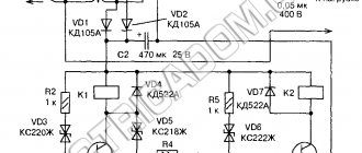
Measurement using a stabilizer circuit
This method allows you to measure the parameters of radioelements by including them in the circuit and the applied voltage of the power source. Depending on the stabilization voltage of the component being tested, it is necessary to have a divider consisting of one or more resistors. The power source is connected directly to a pre-assembled electrical circuit connected with a common minus or a common plus. This circuit is a parametric voltage regulator:
- Let's consider including the circuit in a common minus. The positive wire of the power source is connected to terminal 1 of the divider, which is served by resistor R, and the zener diode under test is connected as a cathode to terminal 2 of resistor R. The anode terminal of the zener diode is connected to the negative terminal of the power source and is a common power bus. The divider resistor is selected in such a way that the applied voltage from the power source reaches such a level that it will allow the zener diode breakdown current to be obtained at pin 2 of the resistor, at which it will open.
- The multimeter switches to the DC voltage measurement mode, after which the positive terminal of the voltmeter is connected to terminal 2 of the resistor, and the negative terminal is connected to the common bus, this is the minus of the power source + the anode of the element under test. It is advisable to have a power source with smooth regulation, which gives this method the ability to test a wide range of stabilized voltages.
Using an example, consider a Zener diode with 12 V stabilization . To do this, it is necessary to apply voltage so that at terminal 1 of the divider it is about 11 V, with the resistance of the divider selected to be approximately 100 Ohms. Voltmeter at pin 2 of resistor (no load). The voltage before and after the divider remains unchanged, depending on the selected resistance. If 12 V or higher is applied to pin 1 of the divider, then at the output of the pin divider the second voltage should not exceed 12 V, which indicates its serviceability.
Divider R is selected in such a way that the source current at pin 2 does not exceed the maximum current of the zener diode, which can lead to failure of the latter.
If the element under study is broken or incorrectly connected to the circuit, then the voltage on the voltmeter will be zero, and the divider will also heat up. If the element is broken, then the applied value at the input of the divider will be higher than 12 V, then the element under test can be considered faulty.
Precision and double-sided devices
Precision zener diodes are tested in a similar way. Double-sided zener diodes are connected to the terminals of the power source without observing polarity.
To check the stabilizer, you need to switch the multimeter to DC measurement mode, observing the polarity. Initially, the amount of power supplied to the stabilizer is checked .
If the voltage is normal, then the multimeter is directly connected to the output of the stabilizer, measuring the voltage value at the output.
Source: https://220v.guru/fizicheskie-ponyatiya-i-pribory/multimetry/kak-proverit-stabilitron-i-stabilizator-napryazheniya-multimetrom.html
Checking according to the stabilizer circuit
The above method is not suitable for bi-directional and precision zener diodes. How to check the voltage stabilizer in this case? It is necessary to include the electronic components being tested in the circuit and apply voltage from the power source. To do this, you need a divider, which consists of one or more resistors. The resistor must ensure breakdown of the zener diode when voltage is applied from the power source.
- The positive wire from the power supply is connected to the first terminal of the divider.
- The cathode terminal of the zener diode is connected to the second terminal of the divider.
- The anode terminal of the zener diode is connected to the negative terminal of the power supply.
- A multimeter in voltmeter mode is included in the circuit. The positive terminal is connected to the second terminal of the resistor, and the negative terminal is connected to the common power bus (negative terminal of the power supply).
- If a voltage equal to or greater than the stabilization voltage is applied to the first terminal of the divider, then at the output it should not exceed this value. This indicates a working zener diode. If the element is broken or incorrectly connected, the voltmeter will show zero. In the case of a broken zener diode, the multimeter readings will exceed the stabilization voltage.
Is it possible and necessary to check the stabilizer with a multimeter?
We've sorted out the zener diode, but how to check the electrical stabilizer? The same one that is installed at home to protect household appliances and electronics.
The voltage stabilizer is a complex device operating under the control of a microcontroller. The presence of “brains” in the circuit allows the device to independently control its state, reporting an error and de-energizing the load in the event of a malfunction. Error messages can have a variety of formats: a red LED, a code on an LED display, or a full message on a graphic or LCD display. If something happens to the stabilizer, you will definitely find out about it even without a multimeter.
Most often, malfunctions occur in relay and servo-drive stabilizers, since in the first case something can happen to the relay, and in the second - to the current-collecting brush or servomotor. The maximum that an ordinary user with a multimeter in hand can do in this situation is to ring the contacts and relay coils, although, in an amicable way, you should immediately contact the service center for the help of specialists. Inept actions can harm not only the stabilizer, but also yourself. There is no point in talking about interfering with the control scheme.