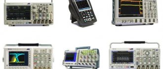
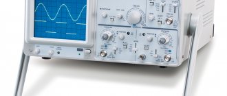
The first attempts to create a device for determining electrical vibrations date back to 1880. They were made by French and Russian physicists. The first oscilloscopes were analog. Since the 1980s, signals have been recorded using digital equipment.
What is an oscilloscope
An oscilloscope allows you to visually study the characteristics of complex signals and calculate time and amplitude parameters. Analogue models display data in real time, while modern digital models allow archiving information and analyzing it. To compare signals, devices with several information inputs are used. Depending on the tasks being solved, there are modifications in the form of attachments to a computer or combined with other measuring equipment.
Short story
The history of the oscilloscope goes back more than 100 years. At different times, such famous people as Adre Blondel, Robert Andreevich Colley, William Crookes, Karl Brown, I. Zenneck, A. Wenelt, Leonid Isaakovich Mandelstam and many others worked on improving the device.
By the way, did you know that the first semblance of an oscilloscope was created in the Russian Empire? This was done in 1885 by Russian physicist Robert Colley. The device was called an oscillometer. The oscilloscopes of that time were very different from those used today!
Main settings
Programmable thermostat W1209
To select an oscilloscope, it is recommended to correctly evaluate the following characteristics:
- to eliminate distortion when working with several high-frequency signals, you should purchase a two- or multi-beam device;
- in different models the error is 5-15%, so limited measurement accuracy should be taken into account;
- digital devices are equipped with color screens, various synchronization devices, and additional service modes;
- The functionality of analog devices is more modest, but they are cheaper;
- the limited capabilities of amplitude-frequency converters make it difficult for high-quality digital electronics to process high-frequency signals;
- Freeze mode with zoom function will help you study the smallest details of complex images.
Before a detailed analysis, you need to clarify what exactly the device is intended for. Next, compliance is assessed according to the following parameters:
- bandwidth;
- frequency range;
- input impedance;
- permissible amplitude values (variable and constant components);
- measurement error;
- isolation between channels;
- internal memory capacity (digital technology).
Design and principle of operation of the device
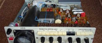
Let us explain the structure of an analog oscilloscope simply, “for dummies.” The device consists of the following elements:
- ray tube;
- power unit;
- vertical/horizontal deflection channel;
- beam modulation channel;
- synchronization and sweep trigger device.
There are controls to control the signal parameters and display it on the screen. Older models did not have a screen. The image was recorded on photographic tape.
Horizontal scan
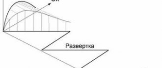
The horizontal connection channel is connected to the scan generator. It produces signals for the horizontal deflection of beams. The X (sweep) generator operates in several modes.
- Internal synchronization. Self-oscillations with manually set frequency;
- External synchronization. The generator is started from the input pulses. It includes three modes: triggering from an external source, on the edge of pulses or their decline;
- Synchronization from power supply (50Hz);
- Manual start. Also called one-shot.
When studying stable signals, it is convenient to use the internal synchronization mode. Under these conditions, the image will be motionless. To increase stability, you can organize frequency capture at the input by a sweep generator.
This mode is also called standby. In it, the generator starts at the moment when the input signal reaches a certain level. Or from an external source. In external synchronization mode, it is convenient to study not very stable oscillations, especially if there is synchronization between the sweep generator and circuits from the same oscillation source. The device can be adjusted to precisely set the level at which the generator starts.
If synchronization occurs from the power supply, then the start of the sweep will be synchronized with the fluctuation of the supply voltage. So synchronization from the network is also provided to monitor interference and distortion. Manual triggering is suitable for studying a variety of non-periodic signals. For example, in logic circuits.
Vertical scan
The vertical deflection channel is called the Y channel, by analogy with the horizontal Y axis in the coordinate system. In it, the input signal under study is processed. This signal enters the channel through an attenuator. An attenuator is a step level control. This is done to ensure that the amplitude of the parameter being measured does not exceed the permissible level. Meanwhile, the picture did not go beyond the screen. The Y channel can send a signal to the horizontal deflection generator to synchronize it.
Typically, the vertical deflection channel operates in open mode. This means that the beam deflection itself will clearly coincide with the signal level. When there is a constant component, it interferes with the observation of oscillations. This happens due to the fact that the picture will be too shifted to the edges of the screen at the top or bottom. It can also go beyond boundaries altogether. This constant component can be removed if you enable the closed input mode. Or adjust the attenuator to fit the screen size.
About the closed entrance. The signal enters through a capacitor, which does not interfere with the alternating voltage. Then both channels have complete amplifiers that generate the required signal levels, which are fed to the deflection plates.
Basic measuring instruments. Oscilloscope: “drawing signal”
“GRAPH” MEANS “DRAWING”
DEVICES FOR STUDYING FORM 3 RADIO SIGNALS
We live in a technological civilization. People have created a second nature - a world of mechanisms, complex machines, radio-electronic devices that use almost the entire known range of electromagnetic radiation. But the human organs of vision can only perceive visible light. We cannot see electric current, radio waves, we cannot measure even the simplest parameters of an electrical signal without the help of instruments. When working with complex electronic equipment, the task of reproducing signal shapes often arises, i.e. dependence of the instantaneous voltage value on time. Its solution allows you to immediately evaluate many parameters of oscillations, for example, distortion of their shape, the presence of interference, and much more. Waveform reproduction plays an important role when checking and configuring audio and video circuits of equipment.
To visualize signals, instruments called oscilloscopes are used, but determining the shape of signals is possible not only in the time domain, but also in the frequency domain. The task of reproducing a signal in the frequency domain is solved by spectrum analyzers and meters of amplitude-frequency characteristics, which will be discussed in the final part of this brochure.
ELECTRONIC OSCILLOSCOPES
Currently, one of the most common radio measuring instruments is the electronic oscilloscope, and this is not surprising, because it has exceptional clarity of presentation of the signals under study, convenience and versatility. An oscilloscope allows you to examine any electrical processes, even if the signal appears at a random moment in time and lasts billionths of a second. From the image on the oscilloscope screen, you can determine the amplitude of the signal in question and the duration of any of its sections. An oscilloscope can measure frequency, phase, modulation ratio, and other complex measurements.
Oscillographic measurements are distinguished by a wide range of frequencies under study (from direct current to microwave), the ability to store and subsequently reproduce signals, high sensitivity and the ability to separate signals from noise.
CLASSIFICATION OF OSCILLOSCOPES
By purpose and principle of operation
Oscilloscopes are divided into: universal, high-speed, stroboscopic, storage and special.
By the number of simultaneously observed signals
they are divided into one-, two- and multi-channel oscilloscopes.
By display device
Oscilloscopes are divided into electron beam and matrix (gas-discharge, plasma, liquid crystal, etc.).
Based on the principle of information processing
Oscilloscopes are divided into analog and digital.
Universal oscilloscopes are general-purpose instruments designed for observing harmonic and pulsed signals. With their help, you can examine single pulses and bursts of pulses, simultaneously obtain images of two signals on one scan, examine in detail any part of a complex signal, and much more. They make it possible to study signals with durations from a few nanoseconds to several seconds in the amplitude range from fractions of millivolts to hundreds of volts, as well as measure the parameters of such signals with an error of 5-7% acceptable for practice. The bandwidth of universal oscilloscopes is 300... 500 MHz and more.
Universal oscilloscopes are divided into two groups: devices of monoblock design and devices with replaceable blocks.
All-in-one general purpose oscilloscopes are the most common type of oscilloscope.
Oscilloscopes with replaceable blocks are distinguished by their versatility, achieved through the use of replaceable blocks for various purposes.
High-speed and sampling oscilloscopes
are used to study transient processes in high-speed semiconductor devices, integrated circuits and switching elements.
Storage oscilloscopes
can save and reproduce an image of a signal for a long time after it disappears at the input. The main purpose of these devices is to study one-time and rarely repeated processes.
Special-purpose oscilloscopes are designed to study television signals; they allow not only to study any part of the television signal with high temporal stability, but also to transmit it digitally to a computer for further processing.
BASIC UNITS OF A UNIVERSAL OSCILLOSCOPE
Rice. 1. Oscilloscope S1-107 General view
In Fig. Figure 1 shows the appearance of the S1-107 universal analog oscilloscope, and Fig. 2 shows its functional diagram. Despite the variety of universal oscilloscopes, their functional circuits are generally the same.
The oscilloscope consists of:
- Cathode ray tube (CRT);
- Vertical deflection channel Y
; - Horizontal deflection channel X
; - Channel Z
; - Multimeter;
- Power supply.
Vertical channel
amplifies or weakens the signal being studied to a value convenient for studying on the indicator.
V/div
control sets the
Y
.
A channel consists of an input divider, which includes connectors, attenuators, and switches; an amplifier that amplifies the signal and splits the polarity of the signal for symmetrical supply to the CRT plates, delay lines and output amplifier. The delay line delays the signal for the time required to trigger the horizontal deflection channel, i.e., the scan generator and amplifier along the X
, so that the horizontal movement of the beam begins before the amplified signal arrives at the CRT plates. This allows you to observe the leading edge of the signal.
Rice. 2. Functional diagram of the S1-107 oscilloscope
Horizontal channel
generates a sawtooth voltage synchronous with the signal being studied to create a time axis on the CRT screen.
The trigger pulse generator produces short trigger pulses. The sweep generator creates a linearly increasing voltage. The rate of increase is adjusted using the Time/div
.
This voltage is supplied to the output amplifier X
) which splits the polarity of the signal and amplifies the scanning voltage to the value required for the required image scale. A positively increasing sawtooth voltage is applied to the right deflector plate of the CRT, and a negative one is applied to the left one. As a result, the beam passes across the tube screen from left to right a set number of scale divisions per unit of time. When the synchronizer is switched to the continuous oscillation mode, a self-oscillating mode of sweep operation is ensured.
The internal synchronization amplifier amplifies part of the signal under study and transmits it to trigger the sweep.
Oscilloscopes have calibrated scans and are equipped with mesh scales for easy reading, which are applied on the inside of the tube screen. This eliminates operator error due to parallax phenomena.
The oscilloscope also includes amplitude and time calibrators, designed to calibrate the scales of vertical and horizontal deflection channels, and power supplies with stabilization.
Many modern oscilloscopes have built-in multimeters that allow you to accurately measure DC and AC voltages, currents and resistances. The S1-107 oscilloscope multimeter works as follows. The measured alternating currents and resistances are converted into alternating voltage. Then the alternating voltages are converted into a direct voltage proportional to the magnitude of the measured parameters. Then the analog signal is converted to digital using an ADC and enters a character generator designed to generate and write characters on the CRT screen.
The oscilloscope can operate in either oscilloscope mode or multimeter mode. Combining these modes is impossible in this model.
DIGITAL OSCILLOSCOPES
Rice. 3. Digital oscilloscope
A digital oscilloscope allows you to simultaneously observe a signal on the screen and obtain numerical values for a number of its parameters with greater accuracy than is possible by reading quantitative values directly from the screen of a conventional oscilloscope. This is possible because the signal parameters are measured directly at the input of a digital oscilloscope, while the signal passed through the vertical deflection channel can be measured with significant errors. These errors can reach 10%.
The parameters measured by modern digital oscilloscopes are: signal amplitude, frequency or duration. On the oscilloscope screen, in addition to the oscillograms themselves, the state of the controls (sensitivity, sweep duration, etc.) is displayed. Provision is made for outputting information from the oscilloscope to printing and other functionality. However, this does not limit the capabilities of digital oscilloscopes. Interfacing digital oscilloscopes with microprocessors allows you to determine the effective value of the signal voltage and even calculate and display Fourier transforms for any type of signal.
Digital oscilloscope devices perform full digital signal processing, so they typically use the latest panel displays.
Modern digital oscilloscopes automatically set the optimal image size on the handset screen.
The functional diagram of a digital oscilloscope (Fig. 4) contains an input signal attenuator; vertical and horizontal deflection amplifiers; amplitude and time interval meters; signal and meter interfaces; microprocessor controller; sweep generator; synchronization circuit and cathode ray tube.
Digital oscilloscopes provide automatic setting of image sizes, automatic synchronization, difference measurements between two marks, automatic measurement of peak-to-peak, maximum and minimum amplitude of signals, period, duration, pause, rise and fall of pulses, etc.
The amplitude and time parameters of the signal under study are determined using meters built into the device. Based on the measurement data, the microprocessor controller calculates the required deflection and sweep coefficients and, through the interface, sets these coefficients in the hardware of the vertical and horizontal deflection channels. This ensures constant image dimensions vertically and horizontally, as well as automatic signal synchronization.
The microprocessor controller also polls the position of the front panel controls, and the polling data, after encoding, is again sent to the controller, which, through the interface, turns on the appropriate automatic measurement mode. The measurement results are displayed on the handset screen, and the amplitude and time parameters of the signal are displayed simultaneously.
Rice. 4. Functional diagram of a digital oscilloscope
PORTABLE MULTIMETERS-OSCILOSCOPES
Recently, a new and rather original variety has appeared on the market of control and measuring instruments: portable digital multimeters-oscilloscopes.
These small-sized and relatively inexpensive devices combine the function of a multimeter, which allows you to measure voltages, currents and resistances, measure capacitances, inductances, parameters of transistors and diodes, and a simple oscilloscope.
The most common multimeter-oscilloscopes on the Russian market are BEETECH (Fig. 5), Velleman, METEX and Tektronix.
Rice. 5. Multimeter-oscilloscope BEETECH 70
Rice. 6. Velleman HPS10 Portable Personal Oscilloscope
The Velleman HPS10 oscilloscope (Fig. 6) does not have the functions of a multimeter, but it is a full-fledged oscilloscope with a bandwidth of 2 MHz and an ADC quantization frequency of 10 MHz. The device has high sensitivity - from 5 mV per 12 divisions, and the sweep range is from 200 ns to 1 hour (!) per 32 divisions. The device can operate from the mains via an adapter or from built-in batteries, which last for 20 hours. The device has an LCD display with a resolution of 128 x 64 pixels. Such an oscilloscope allows you to even view a television signal (albeit rather crudely).
Portable oscilloscopes are often supplied in plastic cases, which, in addition to the device itself, contain adapters, probes, a power adapter and an instruction manual.
In most cases, such a device is quite sufficient for measuring signals during installations.
WORKING WITH AN OSCILLOSCOPE
Modern oscilloscopes provide a rich set of tools for studying waveforms and measuring their parameters.
It is easiest to work with low-frequency signals, for example, with signals in the audio frequency range (Fig. 7), the study of high-frequency signals and signals of complex shapes (Fig. requires additional skills.
Rice. 7. Audio frequency signal on the screen of a digital oscilloscope
Specialized television oscilloscopes have scanning circuits that make it possible to isolate any frame and any line from a television signal, but when working with general-purpose oscilloscopes, you need to choose which synchronization pulses to trigger the scanning - frame or line. Some oscilloscopes have TV-V and TV-H positions on the sweep mode switch (triggering with vertical and horizontal sync pulses, respectively). If there are no such modes, then to view one frame you need to set the scan speed to 2 ms/div, and to view one line - 10 μs/div. Typically, the sweep is triggered by a television signal with a negative polarity of the trigger pulses.
When working with an oscilloscope, it is important to select the correct sweep trigger mode. Most often, the trigger mode is chosen by the signal being studied, the so-called. internal triggering (in two-channel oscilloscopes these modes are called CH1 and CH2). If the equipment under test uses external clock signals, then it is logical to use them to trigger the oscilloscope sweep. This type of synchronization is called external and is usually denoted EXT. If electrical devices are being studied, then synchronization from the network - LINE - may be useful.
A convenient image scale is set with the V/div switch.
Rice. 8. TV signals on the screen of a digital oscilloscope
A two-channel oscilloscope allows, as shown in Fig. 8, Simultaneously view various components of the television signal.
Rice. 9. Damping pulse
Rice. 10. Color burst
By changing the sweep speed and the V/div value, you can examine the general appearance of a complex signal or “stretch” its individual fragment. In Fig. 9 shows one line of a television signal, and Fig. 10 – “stretched” color burst signal.
Rice. 11. Duration measurement
Very often, when working with oscilloscopes, there is a need to measure the parameters of the signals being studied. Analog oscilloscopes are less convenient. In order to determine the amplitude or duration of a signal, you need to calculate how many vertical or horizontal cells the signal under study occupies, and then multiply the number of cells by the value of the V/div or Time/div switch. For example, if the vertical signal occupies 3.5 cells and the V/div switch is set to 100 mV, then the signal amplitude will be 350 mV. The accuracy of this method is low.
Digital oscilloscopes are much more convenient. For example, in order to measure the pulse amplitude on the oscillogram in Fig. 9, you need to turn on the voltage measurement mode, then move cursor 1 to the top of the pulse, and cursor 2 to its base. The oscilloscope will automatically measure the voltage, and the following message will appear on the right side of the screen: Delta – 296 mV.
Durations are measured in the same way, only in this mode the cursors look like vertical lines (Fig. 11).
On the periphery of the screens of digital oscilloscopes (Fig. 7-11) a variety of service information is displayed, which allows, without looking at the device controls, to determine in what position the V/div, Time/div switches, synchronization modes are located, and to become familiar with voltage and duration readings etc.
The interfaces of modern digital oscilloscopes vary from manufacturer to manufacturer, so you should carefully read the User's Guide before you begin.
TIPS FOR WORKING WITH AN OSCILLOSCOPE
- The main measurement mode should be the mode • with a closed input (see Fig. 2). This will protect the device circuits from damage by unexpectedly high voltage;
- Before starting measurements, set the V/div switch to the “coarsest” limit, successively increasing the gain, achieve the desired image size on the screen;
- Use standard probes and probes of the oscilloscope, this increases the accuracy of measurements and reduces the risk of damage to the device;
- If the image on the oscilloscope screen has sufficient amplitude, but you cannot see it, most likely the position of the Time/div switch is selected incorrectly. By changing its position, achieve the most stable image, then select the signal element on which the synchronization will be carried out using the Sync Amplitude knob. If necessary, change the polarity of the synchronization signal and the type of synchronization.
HOW TO CHOOSE AN OSCILLOSCOPE?
An oscilloscope is a complex and expensive device; there are hundreds of models on the market - from the simplest and most budget-friendly to extremely expensive, specialized and precision instruments. How to make the right choice and purchase exactly the oscilloscope that will be useful to you when setting up audio-video equipment? In this chapter we will give you some tips.
Before you start choosing an oscilloscope, you need to clearly understand what tasks will be solved with its help. At the same time, it is necessary to remember about the prospects, since an oscilloscope is not purchased for one year and not to perform one single job.
1. Which oscilloscope should I choose: analog or digital?
Analog oscilloscopes provide the ability to continuously monitor an analog signal in real time, have simple, intuitive controls and are low in cost. At the same time, analog oscilloscopes have low accuracy compared to digital ones; at low scan speeds they are characterized by flickering.
Digital oscilloscopes allow you to “freeze” the image on the screen, have high measurement accuracy, a bright, well-focused image of the signal at any sweep speed, but they are much more expensive, difficult to operate and in some cases display the signal incorrectly.
The undeniable advantages of digital oscilloscopes are also the ability to measure voltages and signal durations “on the fly,” as well as the ability to connect to external recording devices, and the availability of autodiagnostics and autocalibration tools.
2. Determine the required bandwidth
One of the main characteristics of an oscilloscope that influences the choice of device is the bandwidth, which depends on what signals need to be measured and with what accuracy.
Keep in mind that digital oscilloscopes have two fundamentally different bandwidths: repeating (or analog) bandwidth and one-shot bandwidth. Most real-world signals contain many high-frequency harmonics, so wideband oscilloscopes display such signals more accurately.
When making accurate timing measurements, the oscilloscope's bandwidth must be at least three times the first harmonic of the highest-frequency signal being measured. And for accurate amplitude measurements, it is desirable that the oscilloscope bandwidth be ten times greater than the frequency of the measured signal.
Analog oscilloscopes rarely have bandwidths greater than 400 MHz, while digital oscilloscopes can have bandwidths up to 50 GHz.
3. Determine the required number of channels
Two-channel oscilloscopes are the most popular, but recently four-channel models have become increasingly widespread, since their per-channel cost is lower than that of two-channel models, and the capabilities are significantly wider. However, operating such a device can be difficult.
Some oscilloscopes have 2 full channels and 2 additional channels with a limited sensitivity range. In this case, the oscilloscope has only 2 analog-to-digital converters (ADCs), the inputs of which are switched into 4 channels.
4. Determine the required sampling rate (for digital oscilloscopes)
For problems involving single-shot or transient variations, sampling rate is of paramount importance. The sample rate parameter indicates the speed at which the oscilloscope can sample the input signal. Higher sampling rates result in higher bandwidth for single-shot signals and greater temporal resolution.
Most digital oscilloscope manufacturers use a sample rate to bandwidth ratio of 4:1 (with interpolation) or 10:1 (without built-in interpolation) for single-shot signals to prevent signal distortion.
5. Determine the required amount of memory (for digital oscilloscopes)
The amount of memory required depends on the total duration of the signal being analyzed and the desired time resolution. If signals are studied over a long period of time with high resolution, then more memory will be required. Larger memory will allow higher sampling rates to be used at slow scan speeds, reducing the likelihood of receiving a corrupted signal and providing more information about the signal.
Keep in mind that increasing the amount of memory can cause the oscilloscope to slow down significantly as it needs to process more data.
6. Determine the required capabilities to start the device
For most general purpose oscilloscope users, simply edge triggering is often not enough. For many tasks, it is also useful to have additional triggering capabilities that can detect events that are otherwise very difficult to track. The ability to trigger on a television signal allows you to set the device to a specific field or line.
7. Determine the required transient detection capabilities
In principle, any analog oscilloscope is always capable of displaying glitches and jitter. The only question is whether the rise rate in the vertical deviation channel (ultimately the bandwidth) and the brightness of the oscillogram are sufficient to study these processes. Oscilloscopes with pulse noise triggering capabilities allow you to isolate hard-to-detect pulse noise and trigger the oscilloscope on it. This additional feature is very useful when searching for the cause of abnormal operation of the circuit under study.
8. Additional features
Many modern digital oscilloscopes can perform the function of a spectrum analyzer, but in the audio domain it is usually poorly implemented.
Most digital and analog-to-digital oscilloscopes can interface with a personal computer, printer, or plotter via GPIB, RS-232, or Centronics interfaces. In recent years, the USB interface has been increasingly used.
Many modern digital oscilloscopes are equipped with disk drives or flash memory connectors that allow you to save screen images of waveforms (in various formats) and measurement results in numerical form, and then quickly transfer them to a computer for further processing. These capabilities can save time when, for example, you want to paste an oscilloscope screen into a report or copy waveform data into a spreadsheet.
9. Evaluate the ease of use of the device
Try to work with the device, evaluate how easy it is to operate, is it possible to intuitively control the device while the main attention is on the circuit under study? Evaluate the screen's response speed and the time it takes the oscilloscope to execute commands. Does the device have a command memory?
MEASUREMENT OF AMPLITUDE-FREQUENCY CHARACTERISTICS
When monitoring the technical condition of radio-electronic equipment, an important place is occupied by measuring the amplitude-frequency characteristics of its various components.
When measuring the amplitude-frequency characteristics (AFC) of devices or their components, it is convenient to represent them in the form of a four-terminal network. Then the frequency response is the dependence of the modulus (absolute value) of the transmission coefficient of the quadripole on the signal frequency.
The transfer coefficient is the ratio of the power or voltage at the output of a quadrupole to the power or voltage at its input.
If the output voltage is less than the input voltage, the signal is weakened when the signal passes through the quadrupole. Such a four-terminal network is called passive (an example is a passive electrical filter), and the transmission coefficient is the attenuation coefficient.
When the output voltage is greater than the input voltage, the signal is amplified, and the transmission coefficient is the gain. The four-terminal network in this case is called active (an example is an audio frequency signal amplifier).
The value of the transmission coefficient of the quadripole and the value of the signal frequency at which it was determined form a point in the coordinate system, and the collection of such points form the frequency response curve in the required frequency range. In Fig. Figure 12 shows as an example the frequency response of an antenna amplifier operating in the television broadcast range.
Rice. 12. Frequency response of the antenna amplifier
METHODS FOR MEASURING PARAMETERS OF AMPLITUDE-FREQUENCY CHARACTERISTICS
Measurement of the parameters of the amplitude-frequency characteristics of quadrupoles is carried out using a sweep frequency generator (SWG) and an indicator device.
The frequency of the generator smoothly changes according to a certain law in the required frequency band, and the frequency response curve is reproduced on an oscilloscope-type indicator.
The block diagram of the simplest automatic frequency response meter is shown in Fig. 13.
Rice. 13. Block diagram of an automatic frequency response meter
The signal from the frequency converter is fed to the input of the quadripole under study. Due to the presence of this four-port network depending on the transmission coefficient module on the signal frequency, the signal at its output is amplitude modulated. The envelope of this signal, isolated on the detector head, which is part of the indicator device, controls the vertical deflection of the indicator beam, drawing the frequency response curve.
The control of the frequency of the main frequency and the horizontal deflection of the indicator beam is carried out by a modulating voltage block, which simultaneously synchronizes the operation of these two nodes.
In an frequency response meter built according to such a structural diagram, the horizontal position of the beam on the indicator screen corresponds to the frequency at the input of the quadripole under study, and the vertical position corresponds to the value of the modulus of the transmission coefficient at this frequency. Thus, the frequency response curve of the quadripole under study is automatically drawn on the screen.
The automatic amplitude control unit serves to ensure a constant output signal level throughout the entire frequency swing range.
Part of the signal from the MFC is fed to a frequency tag block, in which a whole spectrum of calibration frequencies is generated within the operating range of the MFC. At the moment the frequency of the MCG coincides with any of these frequencies, signals are generated that are fed to the indicator block and observed on the screen in the form of amplitude marks.
An attenuator is used to calibrate the change in the output voltage of the MCU.
Depending on the sweep bandwidth, devices are divided into narrow-band, mid-band, broadband and combined. Narrowband frequency response meters provide a sweep band that is a fraction or a few percent of the central frequency, while broadband meters provide a sweep band that is the full frequency range of the device. Combined devices combine the functions of both narrowband and broadband devices.
Frequency response meters can have a linear or logarithmic amplitude scale.
The most widely used are universal frequency response meters, which allow solving a wide range of measurement tasks. In Fig. Figure 14 shows the domestically produced frequency response meter X1-50, which is used when setting up and testing television equipment. The presence of a built-in grid field generator allows you to check the linearity of the television image, and with the help of an external measuring bridge, check the matching of the antenna leads.
Rice. 14. Frequency response meter X1-50
TIPS FOR WORKING WITH AFC METERS
- An important role is played by matching the device output with the load resistance. If at frequencies up to tens of megahertz the mismatch only leads to a decrease in the level of the output signal, then at higher frequencies it leads to an increase in the unevenness of the output signal in the swing band. Matching the input of the device under study is possible by connecting at the end of the cable connecting them to the output of the frequency response meter, a resistance close to the wave one. If the four-port network under study has a low-impedance input with a characteristic impedance different from the output impedance of the frequency response meter, then it must be connected to the device through a matching device.
- If the output of the device under study is low-impedance, for example, a filter, a television antenna amplifier, or a coaxial transmission line, it should be connected to the input of the indicator device through a matched detector head, and if the output impedance of the quadripole differs from the load resistance of the detector head, a matching device must be installed between them.
- When studying the frequency response of amplifiers, distortions caused by their overload are possible, as a result of which the top of the frequency response curve will appear flatter than it actually is. In this case, a signal with a minimum level must be supplied to the amplifier input.
- When setting up multi-stage devices, such as intermediate frequency amplifiers, video amplifiers, when you need to view the frequency response of each stage separately, use the high-impedance detector head included with the device.
- If your frequency response meter has a two-channel indicator, you can adjust the frequency response of devices by comparing them with reference ones. To do this, the signal from the output of the frequency response meter is fed simultaneously to the inputs of the tuned and reference devices, and their outputs are connected to separate channels of the indicator, the gain of which is set to the same. By changing the device settings, we achieve alignment of its frequency response with the reference one.
- Along with the study of the frequency response of quadripoles, frequency response meters make it possible to solve a number of other measurement tasks, such as measuring the quality factor of an oscillating circuit, the slope of the frequency response, impedances and SWR of the load, and the study of cables.
MEASUREMENT OF RADIO SIGNAL SPECTRUM PARAMETERS
In the practice of working with complex modern electronic equipment, visual observation of the signal shape using an oscilloscope is sometimes insufficient. More sensitive and informative is the analysis of the spectral characteristics of signals
. It is especially important to know the spectral composition of signals at the present time, when the problem of electromagnetic radiation is acute.
Where is it used?
Areas of application:
- always in scientific, technical laboratories, research departments at factories that produce electrical appliances, for example, the manufacturer must know how his products react to interference;
- during in-depth analysis of assemblies, during adjustment and repair of electrical devices: from radio and cellular communications to machine motor circuits. The device is indispensable for radio amateurs.
The device provides visual information about the characteristics of complex signals, shows time and amplitude data of changes, which is important for calculations and determining how the studied object will behave over periods under specific conditions.
What can an oscilloscope measure?
An oscilloscope can measure:
- will show by signals: shape;
- frequency;
- period;
- amplitude;
- phase shift angle;
- comparison of signals;
O-Scope is actually a voltmeter, but it displays online voltage changes; it can be used to indicate the shape of the current by connecting a resistor in series to the network being served (Rt, “t” - current, also shunting). Its Ohm number is selected much lower than that of the circuit so that there is no influence on the circuit. Next, it is calculated using the formula and, knowing the value of Rt, you can find the current.
What are they?
After we have found out why an analog and any other oscilloscope is needed, we can move on to its classification. There are 6 main types of measuring instruments:
- Analog. They are considered classic models of measuring devices. An analog oscilloscope is an instrument for measuring average signals. The lower frequency limit is 10 Hz. The price of such equipment is much lower than digital equipment, which is why it is still popular among novice electronics engineers. The main advantage of analog models is the least distortion of the observed signal. Otherwise, they are much inferior to digital technology. Main components of the device: a. input signal divider; b. scheme of synchronization and deviation of the horizontal plane; c. ray tube; d. power unit.
- Digital storage. The devices offer more research and measurement capabilities, so their price is much higher than analog models. Analyzing abilities are the main advantage of storage devices. By setting certain settings, you can force the equipment to record data in digital format immediately after normalization. The signal data image is more stable, and the user can edit the final result by marking or scaling. Examples of digital storage oscilloscopes: TBS1052B Tektronix, TBS1152B-EDU Tektronix, R&S RTC1000. Main components of the device: a. input signal divider; b. normalization amplifier; c. ADC converter; d. information output and input devices; e. Memory device.
- Digital phosphors. Devices of this type operate on a digital phosphor and are considered the most expensive among all types of oscilloscopes. They are able to simulate changes in the intensity of the output data. This feature simplifies the diagnosis of abnormalities in pulse blocks. Examples of phosphor oscilloscopes: Tektronix MSO DPO2000B, Tektronix DPO70804C, Tektronix DPO72304SX.
- Digital stroboscopic. These models use a sequential signal gating effect. They are used to analyze high-frequency repetitive signals whose frequency exceeds the sampling frequency of the device. They sample multiple signal points over several successive periods and then recreate the original waveform. The operating frequency of this type of equipment exceeds 50 Hz. One of the popular models of sampling oscilloscopes is the Tektronix DSA8300. A distinctive feature of the device is a wide selection of optical and electrical modules for testing.
- Portable. Measurement technology is developing rapidly, so compact equipment has become available for conducting signal studies. The advantage of such devices is their low power consumption and small size. Electronics engineers often use portable equipment in their work. Examples of small measuring technology: R&S RTH Scope Rider series, R&S (HAMEG) HMO Compact series.
- Combined. These devices have built-in spectrum analyzers, so they are able to not only collect information about the incoming signal, but also determine the number of harmonics along with the level. Examples of combined equipment: MDO3024 Tektronix, MDO3104 Tektronix, MDO4054C Tektronix.
It will be interesting➡ Concept and methods of measuring luminous flux
Oscilloscopes are indispensable when measuring the time and amplitude parameters of an electrical signal. Modern device models are also capable of performing spectral analysis.
Kinds
Digital models have recording and archiving functions, which expands the possibilities. To compare results online, devices with several channels are used. There are copies connected to a PC and combinations with other measuring devices.
The choice of analog models (except for simple and educational ones) implies knowledge of a variety of settings, the adjustment is complicated. On the other hand, such devices provide in-depth practice.
Digital models are the recommended choice and will allow you to quickly learn the basics. These are computing systems, with them data acquisition and interpretation are easier and much faster. There are also analog-digital models.
How an oscilloscope works
If you look at quickly passing objects, you will see a blurry line. But if you periodically open the “window”, static frames will be captured. This is the principle of a strobe, the same, but in electronic form the Oscilloscope works.
The action of the “window” is synchronized (the main condition) with the speed of the objects (signal), so when it opens, their place is stable. Otherwise, desynchronization will occur.
The device visualizes periodic changes in real time on the display using a sinusoid or a line of another shape (saw, meander, etc.). Each future segment is similar to the past, it “stops” and is shown (at 1 moment - 1 period).
What does an oscilloscope measure?
The oscilloscope screen displays a two-dimensional picture of the signal that is applied to the measuring input. There are two coordinate axes on the screen. The horizontal is the time axis, the vertical is the voltage. These parameters are measured. And from them the rest is calculated.
The oscilloscope screen displays the signals that are supplied to its inputs. This is, for example, a two-beam analog oscilloscope that shows the waveform at the input (sine wave) and output (square wave) of a pulse voltage converter
Here's what you can measure and monitor with an oscilloscope:
- Voltage (amplitude).
- Time parameters from which the frequency can be calculated.
- Monitor phase shift.
- See the distortions introduced by an element or section of the circuit.
- Determine the constant and temporary components of the signal.
- See if there is noise.
- Calculate the signal-to-noise ratio.
- See/determine pulse parameters.
The signal that the oscilloscope shows is quite informative. The distortions introduced by one or another part are visible; you can track how the shape/amplitude/frequency changes at each point of the circuit, after each part.
In addition to observing the waveform, an oscilloscope can be used to determine the integrity of resistances, capacitors, and inductors (see video below).
General definitions
A cathode ray oscilloscope, or oscilloscope, displays a graph of signal amplitude versus time on its screen. Despite its complex appearance, working with the device does not cause significant difficulties, just like with a strain gauge. Numerous controls help you adjust the image scale at a user-friendly level.
Oscillogram
This test cycle of the operation of internal combustion engine injectors is used to repair electronic components and adjust the ignition angle. The figure clearly demonstrates what an oscilloscope is needed for. Using a conventional multimeter it is impossible to obtain a similar result in order to objectively evaluate the shape of a complex signal.
The purpose of an oscilloscope is easy to determine from the list of typical tasks:
- measurement of time, amplitude and frequency characteristics;
- study of phase shifts in different sections of circuits;
- identification of distortions in the shape, constant and variable components of the signal.
How to connect an imported oscilloscope
You need to carefully read the user manual, prepare a workplace for the device, and properly ground it.
Important! Grounding ensures that when working on the case there will be no dangerous static charge, which could cause a shock if you touched it with your hand.
Next, you need to determine the points to pick up the signal, the zero line, and use a probe to switch them with the attenuator (for unknown signal levels, set the maximum amplitude). Turn on the device, let it warm up, set the necessary modes and take measurements. Take readings and repeat measurements several times.
How to use an oscilloscope
Initially, the operating mode of the oscilloscope is set (self-oscillating, standby or single). Then the attenuator mode is selected or the appropriate voltage divider is installed. This applies to analog devices. Digital at the input analyzes the signal and lowers/increases it to the required level. They have an analytical unit at the input, which itself lowers or increases the input signal to the required level.
The oscilloscope comes with a test cord or cords. Their number depends on the number of input channels of a particular model. If there is one channel, then there is one cord. Maybe two, three and up to sixteen. You need to connect as much as you intend to use.
Oscilloscope cords are difficult to confuse with others. One end has a probe and a branch. This is the "measuring" side. On the other there is a characteristic round connector. This part is connected to the measuring input.
The wire that goes away from the probe is for connecting to ground. It is often equipped with a clothespin or crocodile clip. It is necessary to connect it, the voltage may be different and grounding is necessary.
Oscilloscope Test Cords
Some oscilloscope cords have a switch on the handle that acts as a small amplifier (pictured at right).
After connecting the measuring cords, turn on the device to the network. Then, before work, we move the toggle switch/button to turn on the device to the working position. We can assume that the oscilloscope is ready for use.
Before starting work, you need to check the oscilloscope. We plug it into the network and install the measuring cord. We touch the probe with our finger, a sinusoid with a frequency of 50 Hz appears on the screen - interference from the household electrical network.
If you touch the test probe with your finger, a sinusoidal signal will appear on the screen. The sine wave is not ideal, but if it exists and its frequency is 50 Hz, this means that the oscilloscope is working
Then we take the earth probe and touch it to the measuring probe (we continue to keep our finger on the tip of the probe). The signal disappears (a straight line is displayed). This means that the device is working properly.
As already mentioned, the voltage on the oscilloscope screen is displayed vertically. The entire screen is divided into squares. The vertical division value is set by a switch labeled “V/div”. Which is what Volts means by one division. Before sending a signal, set the beam exactly along the horizontal axis - this is important.
We give a signal and count how many cells the signal rises or falls from the zero level. Then we multiply the number of cells by the “division price” taken from the regulator. As a result, we obtain the signal voltage. In the case of a sinusoid or meander (positive and negative rectangular pulses), the voltage of the half-wave is considered - upper or lower.
Measuring voltage with an oscilloscope
To make it clearer, let's look at an example. In the photo there is a signal, the half-wave of which is understood and lowered by three cells. The division price on the regulator is 5 V. We have: 3 divisions * 5 V/division = 15 V. It turns out that this signal has a voltage of 15 volts.
If you need to measure DC voltage, again set the beam horizontally. Apply voltage and see how many cells the beam “jumped” or fell. Then everything is exactly the same: multiply by the division price and get the constant voltage value.
It might be interesting➡ DC power supply
Frequency is defined as 1/T, where T is the period of the signal. And the period is the time during which the signal goes through a full cycle. For a signal on the screen, this is 5.7 cells. We count from the intersection with the horizontal axis to the second similar point.
How to determine the frequency of a signal using an oscilloscope
Next, we determine the division frequency using the sweep switch. The switch position is set to 50 milliseconds. Take the number of divisions and multiply by the number of cells. We get 50 ms * 5.7 = 285 ms. Convert to seconds. To do this, divide by 1000. We get 0.285 seconds. We count the frequency: 1/0.285 = 3.5 Hz
Types of scans
In different operating modes of the oscilloscope, linear (created by a sawtooth voltage) sweeps may differ:
- One-time. The generator starts once, then locks out. This sweep is needed to capture non-repeating signals.
- Waiting. The launch occurs immediately after the signal. Needed to monitor rare fluctuations.
- Self-oscillatory. The generator turns on periodically when there is no signal. Convenient for displaying frequent periodic pulses.
How are measurements taken?
We continue to describe how to use a digital oscilloscope or analog
It's important to note that they all have a flaw. One feature worth mentioning is that all measurements are carried out visually, so there is a risk that the error will be high
You should also take into account the fact that sweep voltages have extremely low linearity, which leads to an error in phase or frequency measurements of approximately 5%. To minimize these errors, one simple condition must be met - the graph should occupy approximately 90% of the screen area. When measuring frequency and voltage (there is a time interval), the input signal gain and sweep speed adjustment controls should be set to the extreme right positions. It is worth noting one feature: since even a beginner can use a digital oscilloscope, devices with a cathode ray tube have lost their relevance.
How to use an oscilloscope correctly
After the device and types have become clear, you need to understand how to use the oscilloscope.
It's worth starting with calibration. For this purpose, the outputs of the built-in calibrator are provided, in which the frequency and voltage values are strictly fixed. The image on the screen is adjusted to the norm by adjusting the sensitivity and frequency. It should be remembered that the probes of this device have two outputs, one of which is connected to ground - the common point of the entire electrical circuit.
Next, you need to set the voltage level of the measured signal at the input attenuator. If it is unknown, then the maximum position is set. Typically 100V per screen division. By switching the attenuator you need to ensure that the picture takes up most of the screen.
The next step is to set the desired synchronization mode and frequency of the master oscillator. The duration of the oscillation period is set on the frequency regulator. For example, the switch is set to 20 ms/div. This means that the oscillation period, lasting 20 ms, will fit into one division on the coordinate grid. The frequency will be 50Hz.
By adjusting the level and synchronization, you need to achieve a still image.
To make measurements, you need to follow the algorithm:
- Determine the signal level. That is, count how many vertical divisions the image occupies.
- The number obtained in the first step must be multiplied by the attenuator value.
- Determine the duration of the signal. That is, count how many horizontal divisions the image occupies.
- Multiply the number obtained in the third step by the value of the duration control.
- The frequency must be determined by the formula F=1/T, where F is the frequency, and T is the period of oscillation (the shortest period of time during which the oscillation occurs).
Classification
Capacitor energy
Based on the type of circuitry (electronic components) used, a distinction is made between digital and analog measuring instruments. Simple models show only a dynamic picture. Modern ones are equipped with a memory function to provide better conditions for studying complex processes. Some electronic oscilloscopes are capable of displaying up to 14 or more signals simultaneously. To study optical signals, manufacturers produce stroboscopic high-speed modifications.
Special mention should be made of specialized set-top boxes that connect via a standard port or communication card to a laptop (desktop computer). Such combined equipment can be reconfigured using specialized software.
The vst plugin provides convenient processing of wave processes in the audio range
The difference between an analog oscilloscope and a digital one
The fundamental difference between these varieties lies in size, storage capabilities, and processing methods. For example, analog oscilloscopes transmit signals in real time, without recording capabilities. Analog-digital models allow you to see the dynamics of changes in time or amplitude.
Fully digital analogues, accordingly, are capable of digital processing, digitizing a sine wave and transmitting the resulting information to the display. It should be taken into account that cyclic memory does not allow storing large amounts of data. Therefore, if the user needs to record signals that are five to ten minutes long, an oscilloscope with a large memory depth (storage) will be required.
There are also digital oscilloscopes with a segmented memory mode, which allow you to record only certain information, the form of which is specified by the user through the menu. This makes it possible to study one-time or rarely repeated processes.
Processes measured
According to the principle of operation, devices are divided into:
- Special. They have blocks for intended use (for example, television oscilloscopes).
- Stroboscopic. Sensitive instruments for studying short-term repetitive processes.
- Express. Used to record processes at high speed (with an accuracy of nano- and picoseconds).
- Memorable. Save the resulting image. Typically used to study rare, one-time actions.
- Universal. Explore different processes.
Using a Digital Oscilloscope
A wide sweep range allows you to monitor even nanosecond intervals, observe signals at various points in the circuit, and measure the rise time of a pulse, which is of great importance when working with digital equipment.
Equipment of various types helps to check, configure and adjust a variety of radio electronics, electronic equipment, repair household appliances and diagnose vehicles. Such devices are widely used in medicine, applied, laboratory and research fields.
Synchronization with the observed signal
The special motor trajectory of the beam on the screen during the deployment process allows you to obtain a given fixed image on the display. It must move along the same curved line. This process is ensured by a synchronization circuit, which starts the sweep at the same edge and level of the signals under study.
As an example, it is permissible to consider the situation of studying a sinusoidal signal with the circuit configured in such a way that the start of the sweep in the rise of sinusoids will have a value of zero. At the moment of launch, the narrow beam will outline several similar or one single wave, which will be influenced by the speed configured in advance. The absence of a re-trigger will force you to wait for the next passage of a wave with a zero value with a rising edge.
Without synchronization with the signal being studied, the picture on the display will look fuzzy and blurry. This is caused by the simultaneous display of different parts of the signal under study on the screen. Basic settings available to each operator: launch type and its level.
Errors when choosing and working with an oscilloscope
Understanding how to use an oscilloscope comes only with practical experience; theoretical knowledge is not enough - you need to make all the settings, switching and measurements by hand. A digital device greatly facilitates the process, but the cost of the equipment is very high.
Important! You should not buy an old Soviet device, because... Measurement errors will not provide reliable data, and it will no longer be possible to calibrate it.
It is imperative to follow safety precautions: the voltage on a CRT is like on a TV picture tube - it won’t kill, but it can cripple. The passport and manual describe how to work with the oscilloscope, but common sense has not been canceled: you need to experiment carefully.
Additional features and tips
Oscilloscopes can be dual-beam. Dual beam oscilloscopes are needed to image more signals. These devices are equipped with a special CRT with two beams. Its design consists of a glass bulb in which there are two systems of deflecting plates, independent of each other.
One signal is selected as the main signal, the oscilloscope is synchronized with it, and the others are monitored relative to the main signal. To increase the input range, input dividers of 1:10 or 1:100 are used, raising the upper permissible value to 10 or 100 times. This must be taken into account in further calculations to avoid mistakes. The presence of an input divider also increases the input resistance.
Digital oscilloscopes do not require manual calculation of amplitudes and frequencies. These values are displayed on the screen. Moreover, the image can be stored in memory and printed.
When there are no additional Y inputs, to determine phase shifts you need an oscilloscope with an X input, with the internal sweep generator disabled. Then, by applying oscillations to these inputs, phases and frequencies can be compared using “Lissajous figures”.
Next
MiscellaneousWhat is active power?
Specifics of product selection
When purchasing such highly specialized equipment, a number of important parameters should be taken into account. First of all, you should pay attention to the following:
- Bandwidth. On average, the band should be 5 points higher than the frequency value of the signal being studied. To use a simple audio amplifier and digital circuit, 25 MHz will be sufficient. Scientific research and professional research will require the use of a device with a minimum bandwidth of about 150 MHz.
- Type of food. In case of carrying out work away from the network or on the road, it is recommended to purchase a model with a battery. In any other situation, it is advisable to use network-powered equipment.
- Sampling frequency. This item affects the quality of image resolution on screens and the number of signal samples per second. For a more accurate image, an increase in the number of signal points will be required. Frequency is also important for measuring single-shot and transient events.
- Number of channels. Channels affect the number of independent signals shown on the display. Provide the ability to analyze and compare several graphs simultaneously. Working with simple technical devices does not require more than 3 channels. More advanced equipment should be equipped with a logic analyzer and 16 channels.
You may be interested in this Device for an electrician: voltage tester
