"PPTC" redirects here. For information about the Pacific Paramedic Training Center, see Pacific Open Learning Health Net.
| This article need additional quotes for verification . |
Recoverable fuses - PolySwitch devices
A resettable fuse
or
Polymer Positive Temperature Coefficient
(
PPTC
) device is a passive electronic component used to protect against overcurrent errors in electronic circuits.
The device is also known as a multifunctional
or
polyfuse
or
polyswitch
. They are similar in function to PTC thermistors in certain situations, but work with mechanical changes instead of charge carrier effects in semiconductors. These devices were first discovered and described by Gerald Pearson at Bell Labs in 1939 and are described in US Patent #2,258,958.[1]
Operation
The PTC polymer device consists of a non-conducting crystalline organic polymer matrix that is loaded with black carbon particles[2] to make it conductive. When cold, the polymer is in a crystalline state, with carbon penetrating into the areas between the crystals to form many conducting chains. Because it is conductive ("initial resistance"),[3] it will allow current to pass. If too much current is passed through the device, it will begin to heat up. As the device heats up, the polymer will expand, turning from crystalline to solid. amorphous state.[4] The expansion separates the carbon particles and disrupts the conductive paths, causing the device to heat up faster and expand further, further increasing resistance.[5] This increase in resistance significantly reduces the current in the circuit. There is still a small current flowing through the device (leakage), which is enough to maintain the temperature at a level that will keep it in a high resistance state. Leakage current can vary from less than one hundred mA at rated voltage to several hundred mA at lower voltages. The device can be said to have a locking function.[6] Holding current is the maximum current at which the device is guaranteed not to operate. The tripping current is the current at which the device is guaranteed to turn off.[7]
When the power is turned off, heating due to leakage current stops and the PPTC device cools down. As the device cools, it regains its original crystalline structure and returns to a low-resistance state where it can hold the current specified for the device.[6] This cooling usually takes a few seconds, although a tripped device will maintain a slightly higher resistance for several hours unless the power in it is weaker or is used frequently, slowly approaching the initial resistance value. Reset often does not occur even if only the fault is cleared while power is still supplied because the operating current may be higher than the PPTC holding current. The device may not return to its original resistance value; it will most likely stabilize at a much higher resistance (up to 4 times the initial value). It may take hours, days, weeks, or even years for the device to return to a resistance value similar to its original value, if it returns at all.[8]
The PPTC device has a current rating and voltage rating.[9]
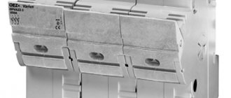
Housing types, overall and installation dimensions
Self-resetting fuses are available in several types of housings:
- Disc type with radial wire leads: MF-R, MF-RX series (Fig. 5). General use, for printed hole or surface mounting.
- For surface mounting: MF-SM, MF-MSM series. General use.
- In flat rectangular cases with strip leads: MF-S, MF-LS series (Fig. 6). Used to protect batteries from short circuits and overheating during charging.
- In a packageless design in the form of disks without leads.
Marked with the manufacturer's logo, series identifier, normal operating current code (Ihold) and production date code. Self-resetting fuses in the open-frame design in the form of disks are not marked.
Applications
These devices are often used in computer power supplies, largely due to the PC 97 standard (which recommends a sealed PC that the user should never open) and in aerospace/nuclear applications where replacement is difficult.[ citation needed
] Another use for such devices is audio protection. music speakers, especially tweeters, from being damaged by over-drive: by connecting a resistor or light bulb in parallel with the PPTC device, a circuit can be designed that limits the total current through the tweeter to a safe value, rather than turning it off, allowing the speaker to continue operating without damage when The power amplifier provides more power than the tweeter can handle. Although a fuse may also offer similar protection, if the fuse is blown, the tweeter will not be able to operate until the fuse is replaced.[10]
Self-restoring fuses SMD 1812
| 0.1A | 0.3A | 30V | 100A | 0.8 W | 1.5 sec (0.5A) | 1.6 ohm | 15 ohm | |
| SMD1812P020TF | 0.2A | 0.4A | 30V | 100A | 0.8 W | 0.02 sec (8A) | 0.8 ohm | 5 ohm |
| SMD1812P050TF | 0.5A | 1A | 15V | 100A | 0.8 W | 0.15 sec (8A) | 0.15 Ohm | 1 ohm |
| SMD1812P050TF/30 | 0.5A | 1A | 30V | 100A | 0.8 W | 0.15 sec (8A) | 0.15 Ohm | 1 ohm |
| SMD1812P075TF/24 | 0.75A | 1.5A | 24V | 40A | 0.8 W | 0.2 sec (8A) | 0.11 Ohm | 0.29 ohm |
| SMD1812P110TF/33 | 1.10A | 1.95A | 33V | 20A | 0.8 W | 0.5 sec (8A) | 0.06 Ohm | 0.20 ohm |
| SMD1812P125TF/16 | 1.25A | 2.5A | 15V | 40A | 0.8 W | 0.4 sec (8A) | 0.07 Ohm | 0.25 ohm |
| SMD1812P150TF/24 | 1.5A | 3.0A | 24V | 20A | 0.8 W | 1.5 sec (8A) | 0.04 Ohm | 0.12 Ohm |
| SMD1812P200TF | 2.0A | 3.5A | 8V | 40A | 0.8 W | 2.00 sec (8A) | 0.02 Ohm | 0.06 Ohm |
Packaging: In a blister tape on a reel with a diameter of 180 mm, 2000 pieces of self-restoring fuses for surface mounting of standard size 1812 (1812P010TS - 1812P050TG/S) and 1500 pieces 1812P125TS, 1812P200TS.
Trade names of devices
These devices are sold by different companies under different brand names, including Multifuse
(Bourns),[11]
PolySwitch
(TE connection)[
quote needed
], and
Polyfuse
(Littelfuse)[
quote needed
].
PolySwitch is the earliest product of this type[ citation needed
], having been invented at Raychem Corporation (now TE Connectivity) and introduced in the early 1980s[
citation needed
].
Thanks to the general availability, electronic engineers and technicians[ WHO?
] this device is often referred to as a "multi-switch" or "polyfusor" in a generic sense, regardless of the actual brand.[
citation needed
].
Self-restoring fuses SMD 2920
| 2.0A | 4.0A | 24V | 40A | 1.5 W | 5.0 sec (8A) | 0.05 Ohm | 0.125 Ohm | |
| SMD2920P250TF | 2.5A | 5.0A | 15V | 40A | 1.5 W | 5.0 sec (8A) | 0.035 Ohm | 0.085 Ohm |
| SMD2920P300TF/15 | 3.0A | 5.0A | 15V | 40A | 1.5 W | 20.0 sec (8A) | 0.015 Ohm | 0.048 Ohm |
Packaging: In a blister strip on a reel with a diameter of 180 mm, 2000 pieces of self-restoring fuses for surface mounting, size 2920.
Advantages and disadvantages
The advantages of fuses include:
- full guarantee of disconnection of the emergency section of the circuit;
- stability of technical protection characteristics;
- can be used for selectivity;
- performance;
- reliability;
- simplicity of design.
Main disadvantages:
- in three-phase networks, phase imbalance is possible;
- probability of prolonged arc burning;
- influence of the environment (temperature) on the characteristics of fuse links;
- difficulty in setting up selective protection;
- the need to replace the insert after each protection operation.
Purpose and principle of operation
The main task of fuses is to protect the electrical network and electrical equipment from overcurrents that occur during a short circuit or as a result of critical overloads. At the same time, they ensure uninterrupted operation of the protected circuits in nominal mode.
Unlike a circuit breaker, often used in electrical engineering, a fuse-link operates only once, after which it must be replaced. However, such a device works with one hundred percent probability, while the automation may fail after repeated shutdowns. That is why fusible links are used to protect expensive equipment. They do not refuse to use these protective devices in power circuits.
Design and principle of protection
The design of a fuse has two main elements: a body (holder) with contacts and a fuse insert (Figure 1). Strictly speaking, only a combination of these elements can be called a fuse. Very often the fuse link part (especially if it is replaceable) is called a fuse. In this article we will also sometimes adhere to this tradition.
Rice. 1. Fuse design
The working element of the insert is a conductor made of copper or a metal alloy. Thanks to this fusible element, circuit shutdowns occur in critical situations.
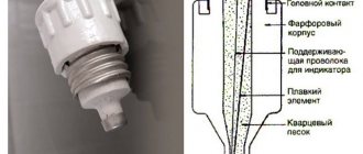
The fusible element can be one or more copper wires, a plate or a shaped part. These conductors are placed in a heat-resistant housing: glass, ceramic (Fig. 2) or plastic. Depending on the purpose, the space around the fusible element can be filled with quartz sand or surrounded by an easily evaporating substance intended to extinguish the electric arc.
Rice. 2. Ceramic fuse links
When rated currents pass through the insert wire, it heats up slightly without reaching the melting point. But in short-circuit mode, the current increases sharply, which leads to melting of the inserts. This causes the chain to break.
Heating of the fuse also occurs during overloads, that is, as a result of exceeding the rated voltage in the protected section of the circuit. When the operating voltage reaches a value called the shutdown current, the temperature of the fuse element increases to the melting point and the circuit breaks. After restoring the circuit parameters, the fuse link must be replaced.
Fuse links have a certain response inertia. With a short circuit, the delay is unnoticeable, since in this case the fuse element heats up at lightning speed.
The situation is different in cases with overloads. It takes longer to reach the melting point. Therefore, in order to increase the response speed, the elements of the inserts are given a special shape and loaded with elastic forces (one end of the plate is connected to an extended spring).
In some models, under the action of a spring, a pin called an operation indicator comes out (Figure 3). It acts as an operation indicator and indicates that the insert needs to be changed.
Rice. 3. Structure of the fuse link
The numbers in the figure indicate:
- I – cartridge;
- 2 – fusible plate;
- 3 – tin balls;
- 4 – fuse link;
- 5 – quartz sand;
- 6 – spring;
- 7 – textolite washer;
- 8 – trigger mechanism of the trigger indicator;
- 9 – cap;
- 10 – rim of the cap;
- 11 – operation indicator;
- 12 – asbestos-cement gasket;
- 13 – cement filling.
In some cases, to increase the response speed, inserts with parallel tensioned wires of different diameters are used. Burning out the thinnest wire increases the load on the remaining elements, accelerating their melting.
In order to reduce overvoltages, some designs of inserts use wires with different sections of individual sections. When such a fuse is triggered, the section with the smallest cross-section of the insert burns out first. If vapors of molten metal provoke an electric arc at the breaking point, a section with a large cross-section will burn out.
The design features of fuses can be recognized by their markings. Unfortunately, time-current characteristics are not applied to all types of products. But models on which alphanumeric codes are applied can be easily classified according to their purpose.
Replaceable fuse link
It is generally assumed that fuses are replaceable parts and should be installed with the correct socket. This interchangeability is no longer necessary and may even be undesirable. Especially in low-power devices such as cell phones, chargers, plug-in adapters and electronic toys, and a common option for mid-power devices including power tools, industrial controllers and higher power circuits - car chargers. Devices may require different fuse ratings to protect different circuits, including sensitive signal paths.
From a safety point of view, the fuse should not be replaced unless the actual cause of its failure is known. In most cases, a blown fuse means the electronics are permanently damaged and replacing them is a waste of time. For example, if a fuse is part of the protection circuit of a lithium battery and its charging circuit, it is the same critical component of that function. Therefore, it is important to find the reason for the “blown” fuse, and not just replace it blindly.
The fuse holder and its contacts increase concerns about the reliability of overcurrent protection due to corrosion, vibration and other environmental factors. So there is a size issue: after all, a fuse soldered to a PCB without a rim will be smaller and easier to integrate.
The problem of taking up space on the board is solved with SMD versions. They can also be assembled automatically in a typical SMT process, so it's no surprise that they're gaining popularity. But to use them correctly, you need to go beyond traditional wire fuses.
A wide range of SMD fuses will solve the problems of modern radio design. For example, one company has developed a family of SinglFuse SMD fuses that are available in a wide range of operating currents and voltages. The range includes seven different solutions: sputtered thin-layer metal, thin-layer plate, multi-layer ceramic, ceramic laminate, wire core, ceramic tube and cube.
The fuse can be a small sealed SMD component
The technology used for production is related to the electrical parameters of these elements, such as rated current, rated voltage, breaking capacity, I2t integral and operating temperature range. AEC-Q200 compatible versions are available for automotive applications that require advanced specifications and reliable performance at wide temperatures, one of many industry requirements.
Types and device
Depending on the tasks being solved, the classification of fuses can be as follows (Figure 5):
- blade guards;
- low-current fuse links;
- plug fuses;
- quartz;
- cork type
- gas generating.
Rice. 5. Types of fuses
There are also self-resetting fuses, inertial and hinged (Fig. 6). Inertia-type products are designed to protect electric motors, which create heavy loads when starting. Fusible elements heat up but do not burn out. After the engine starts, the slow-blow fuse goes into standby mode.
Folding inserts are used to protect power lines. In emergency situations, the fusible element opens the circuit. Under the influence of high temperature, the insert elongates, resulting in pressure on the trigger mechanism, which throws the fuse out of its socket. This ensures reliable shutdown of the emergency section.
Rice. 6. Flip-up fuses
The design of a self-resetting fuse differs from other types of electrical devices. The working element of the product is a polymer with a positive temperature coefficient of expansion. The polymer contains carbon inclusions that conduct current.
When heated, carbon bonds are broken, resulting in an increase in electrical resistance. When the melting temperature of the polymer is reached, the resistance tends to infinity, that is, the circuit opens. When cooled, the electrical conductivity of the polymer resumes. The fuse is self-resetting.