With the development of technology, the electronic part of the car is becoming more and more modern. More and more new elements appear in it, and it becomes more complex. In addition, in electronics, each of the elements is inextricably linked with the others, so the failure of one of them can immediately cause failures in other components of the electrical circuit. To avoid such a development of the situation in cars, manufacturers began to install fuses. They protect the electronic circuit from short circuits by opening the circuit and cutting off the current in it. As part of this material, we will try to describe existing methods for checking fuses.
Types of automobile fuses
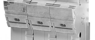
As a rule, fuses in cars are located in special blocks. Basically, two or more units of such devices are installed on a vehicle. One of them is located under the hood in the trunk area. This element is the main one and consists of the largest number of fuses. As for the other fuse box, its location may differ depending on the make of the car. On some models it may be located under the dashboard inside the car. Car batteries are classified according to two criteria: current rating and size. It follows that fuses can be:
However, in addition to dimensions, before purchasing a particular type of fuse, it is extremely important to pay attention to its rated current. Most vehicle components are installed with a value of this parameter in the range of 5-30 A.
Analogue LM324
List of imported analogs of LM324: ULN4336N, GL324, LA6324, IR3702, HA17324, MB3614, NJM2902D, SG324N, TDB0124, UA324, TA75902P, Russian 1401UD2 and 435UD2.
Scope of application
The LM324 found its greatest popularity using standard negative feedback circuits. It is used in the creation of various multifunctional devices: integrators, differentiators, demodulators, logarithmic amplifiers, adders, adding-subtracting devices, amplitude regulators, generators, etc. Due to the constant improvement of the device in question, many different devices using lm324 appear, for example:
- UPS;
- motion sensor circuit for lighting;
- Neptune incubator thermostat diagram, etc.
How to check a car fuse?
If the circuit in the machine is overloaded, there is a very high probability that the circuit itself may break, which will lead to failure of the fuses. However, loss of functionality of an electrical device will not always indicate problems with the fuse. Very often, the cause of the problem can be completely different reasons. To accurately determine the source of the problem, it is important to promptly diagnose the element in the fuse box that is directly responsible for the operation of this device. This can be done quite quickly and easily by following the instructions for the car. There, the manufacturer indicates the installation locations of fuses in the block that are responsible for specific electrical devices.
How to visually recognize the problem?
Many motorists believe that the most acceptable and fastest way to find faults in electronics is a visual inspection. To carry out such a diagnosis, it will be necessary to remove the fuse from the unit and then inspect it for interruptions in lighting. If there are broken wires in the element or there are traces of burnt marks, it is very likely that the circuit break and equipment failure occurred due to the failure of the fuse. Basically, in this way, violations are detected using a glass or plastic fuse.
Checking the fuse with a multimeter: how to do it?
Another good method for detecting a faulty fuse is to use a multimeter. Using it, you can check the car fuse in two ways:
- Battery charge monitoring;
- Checking the ignition coil.
This method is simple and allows the driver to pinpoint the problem in minutes. However, not all circuit problems can be identified in this way. In the event of a malfunction of the door lock or sound signal, it is better to carry out diagnostics using a resistance.
We'll tell you more about how to check fuses in a car in this video:
Every year, electrical circuits of cars include more and more elements that are so closely interconnected that the failure of one of them, as a rule, leads to the failure of another (one or more). To minimize such situations, cars began to be equipped with fuses, the main purpose of which is to prevent short circuits in electrical circuits. The principle of operation is simple: when too much voltage is applied to a circuit, the fuse will blow and be destroyed, causing the circuit to open and therefore protect all devices connected to it. Let's assume that such a gap has already occurred. How do you find the right one among the many fuses that needs to be replaced? - the answer is below.
Main reasons
Each fuse is responsible for the stable operation of certain electrical circuits. If the low-melting element melts, then some kind of malfunction has occurred. Sometimes such situations are isolated, that is, after replacing the fuse, the problem does not recur. But often it turns into a trend.
Experts identify several main reasons why protective fuses burn in a car. If you understand the reason and find the source of the trouble, you will be able to return the machine to normal operation.
- bad connection. It is possible that during installation or during operation on uneven roads, the quality of contact between the fuse and the block was impaired. Sometimes it’s all about the quality of the products themselves, which are not able to guarantee a tight connection. In this situation, the best solution would be to purchase higher quality security elements;
- wear. There is a fairly widespread opinion that the first time the load on the fuse is exceeded, it immediately fails. This is not entirely true. When the situation is critical and the load is really huge, the fuse element is immediately destroyed to break the circuit. But when the load is only slightly higher than normal, the fusible component gradually fails. The cross section decreases, and as a result, after several load sessions it finally burns out. Since fuses are consumables, they tend to fail without causing serious problems in the car itself;
- wrong choice at face value. Each fuse has its own rating. This is the current strength that he is able to pass through himself. If an element with an incorrect value is installed, it cannot withstand the load acting on it and quickly fails;
- sudden surges in voltage. If a sharp surge occurs in the electrical circuit for which the fuse is responsible, the element melts and fails;
- disturbances in the current path. Each fuse is designed for a specific load and is installed on the electrical circuit corresponding to its rating. If you shorten the length of the circuit, the resistance will decrease, and the fuse will pass a higher current through itself. On modern cars, electronics are not designed to withstand overloads. Therefore, special sensitive protective elements are installed in their electrical circuits. Under critical loads, they melt and break the circuit, thereby protecting the equipment from breakdowns.
When devices and components that depend on electricity fail in a car, it is recommended to first check the condition of the fuses before repairing or replacing them. They could simply burn out, causing the systems to stop working. A simple replacement of the element will restore functionality.
Method number 1 - how to check the fuse in a car using a diagram.
The fuse location diagram is always drawn in the instructions for any car. This is the best assistant in finding a burnt-out device.
All that is required of you is to determine, based on this diagram, the location of the fuse responsible for the non-working element of the electrical circuit (radio tape recorder, dimensions, cigarette lighter, stove, etc.) and replace it with a new one. If, after such a replacement, the malfunction “disappears,” it means that the problem was, in fact, in this fuse; if not, then either the fuse is not the same, or the cause of the malfunction must be looked for elsewhere (wires (contacts) of a broken device, a burnt-out light bulb, etc. .).
By the way, it is not at all necessary to replace the fuse with a new one; a visual inspection will be enough.
Chip LM324 (N)
The LM324 microcircuit consists of four identical operational amplifiers (op-amps) assembled in a single package, operating from a single power source over a wide voltage range. Each opamp includes an input differential stage, short-circuit protection and internal frequency correction at unity gain.
The characteristics and low cost of this device ensure its widespread use in amateur radio circuits and industrial electronics. It is ideal for use in compact, portable electronic devices.
Method No. 2 – visual research.
This can be done both in relation to a specific fuse, and you can check absolutely all these elements in the car, because almost every one of them today has a transparent case in which the “wire” is clearly visible even to the naked eye.”
Its integrity is the main characteristic of the fuse and should be checked by removing the protective devices one by one.
However, it should be recognized that the large number of fuses found in a modern car and their dimensions are far from conducive to quickly finding a blown element, so very often motorists search not visually, but using a special device - a multimeter (tester).
Physical examination
At the moment, all fuses are made with a transparent plastic case, that is, the “thread” located inside is visible to the naked eye. If the fuse is blown, simply pull it out of the connector and check, this is the “visual method”!
Why is it complicated and not always used - yes, because there are dozens of fuses in modern cars (can reach up to 30 - 40), and the cooler the car, the more there are. And it’s visually impossible to figure out which one burned out!
They are installed in sockets and only the back is visible. Here you need to combine a diagram (the first method) and a physical examination. But there is a much faster and fairly easy method of checking, we use a multimeter if you have one.
Method number 3 - how to check the fuse in a car with a multimeter.
Using a multimeter, you can check the serviceability of the fuses in the car, both in the removed and “in place” state.”
In the first case, you should put the device into sound test mode.
And then install its probes on the fuse contacts.
If you hear a squeaking sound, the device is working properly.
However, in the absence of a circuit or exact certainty that a specific fuse is responsible for everything, removing and calling each one is a very time-consuming and tedious task, so it is recommended to do an on-site check to save time and effort. Everything has the same sound, but not the contacts themselves, but their open points. Touch them with a multimeter and immediately determine whether the fuse is working.
Worth remembering before work
You need to remember that fuses are in the electrical circuit, so you need to take precautions:
- The car must be turned off
- The ignition must be turned off
- The battery must be installed and the terminals must be connected, otherwise there will be no “power” to the electrical circuit
- Do not bridge the contacts of one fuse with another using a multimeter.
What I would like to add in conclusion, guys - the first two methods are available to everyone, that is, it’s trivial to pull it out and look, but the third one with a tester... buy it, it’s a really useful thing in the car, if you decide to figure it out yourself, we just can’t replace it!
Now we are watching a detailed but useful video.
I hope I helped you, sincerely your AUTOBLOGGER.
( 10 votes, average: 4.90 out of 5)
Similar news
How to check the generator on a car without removing it. With or without a multimeter.
Generator overrunning clutch. What is it and what is it for? Important.
What is OBD2 and what does ELM327 have to do with it? How to use them in cars.
Source: avto-blogger.ru
Video.
For many car owners, the relay turns out to be a very incomprehensible thing. The failure of various equipment may depend on its malfunction, so you need to know how to check the operation of the relay.
To understand the operating principle of this device, it is worth reading the very detailed article How relays work in a car. In short, there is a small electromagnet installed inside the relay housing. When voltage is applied to its contacts, it attracts a jumper and closes the power line contacts - the equipment turns on. Based on this, there are some relay malfunctions that can lead to its failure.
When troubleshooting any equipment connected via a relay, you need to check whether it is working. In modern cars, relays are mounted in mounting blocks, so they will be based on this. If you have a "free-standing" relay, the testing principles are the same.
Checking the presence of power at the control contacts
When certain conditions necessary to turn on the equipment powered by the relay are met (for example, when the headlights are turned on from the interior), the relay should operate. If there is a click, skip straight to the next section of the article on power contacts. If there is no click, you need to check the voltage at the control contacts. You can determine the presence of voltage using a conventional test lamp or multimeter. Also, the multimeter can show low voltage, which the light bulb “will not notice.”
To measure the voltage at a relay contact, in some cases it is enough to slightly pull it out of the mounting block socket and touch one of the control contacts with a test lamp or multimeter probe. Therefore, the second probe must rest against the metal of the housing. However, it is safer and easier to completely pull out the relay and insert the probe into the desired slot on the block.
If there is no voltage at any of the control contacts, the relay will not turn on and, most likely, is not responsible for equipment failure. You must look for the reason why the current is not reaching the relay.
In order for the magnet inside the relay to work, in addition to the “plus” there must also be a “mass”, that is, a connection with the body. You can check its presence using the same “control”. Place one lamp probe on the positive pole of the battery, and the other in the ground socket of the mounting block. Just do not connect these places with a regular wire - this will lead to a short circuit! A light bulb or multimeter will eliminate this danger and indicate whether the appropriate outlet is grounded.
We check the presence of voltage at the power contacts of the relay
If the relay operates, this means that the electrical control circuit is working, the magnet is activated and the jumper is moving. In this case, it is necessary to check the presence of voltage at the power contacts of the relay. There is always voltage on one contact, and on the second it should appear when the relay is turned on. With the equipment turned off and connected through the relay under test, locate the power contact that is receiving voltage. To do this, insert a test lamp or multimeter probe into the corresponding socket of the mounting block, and the other end into the body.
If there is no voltage at any of the power contacts, then the power line is faulty and the relay has nothing to do with it. The reasons for power line failure can be different, but first you should check the fuse. If there is voltage at one of the power contacts of the relay, then when the relay is turned on (the relay clicked, there is voltage at the control contacts), there should be voltage at the second power contact.
If the relay is turned on and there is voltage at only one power contact, no current flows through the relay contact group. This usually happens due to burnout of the jumper contacts that close the power line. Replacing such a relay with a new one is easier, since disassembling this structure and trying to clean the jumper is a rather complicated and unreliable task. In addition, the cost of most relays is low.
Pin Configuration
It is produced in DIP-type packages: plastic CDIP, ceramic PDIP or SO-type for surface mounting: SOIC, TSSOP. Structurally, the device has 14 pins. Therefore, in some technical descriptions, the designation DIP-14 or SO-14 is found.
The assignment of pins for different cases is identical: 2,3, 5,6, 9,10, 13,12 - inputs, 1,7,8,14 - output, 4 - plus power supply, 11 - minus power supply.
Specifications
- Supply voltage range Upit. (Vcc): unipolar source: +3…30 V, bipolar source: ±1.5…±15 V (V);
- Differential input voltage Udifferential (VIDR): 32 V (V);
- Input ref. Uin. (VICR) from -0.3…32 V (V);
- Input current IICR (with negative VICR) 5 mA (mA);
- Input current IICR (with positive VICR) 0.4 mA (mA);
Electrical parameters (at Usupply +5 V and TA +25 °C):
- Bias voltage at the input Ucm (VIO) from 2...7 mV (mV);
- Input bias current Iin.(IIB) from 45...100 nA (nA);
- Output nap. Uout.(Vout): from 0… Up. – 1.5 V (V);
- Gain (K): 100 dB;
- Bandwidth (f) 1 MHz;
- Current consumption without load Ipot. (ICC): no more than 700 µA (µA);
- Input current difference (shift current) Isdv. (IIO) from 5...30 nA (nA);
- Power dissipation PP max (P tod) depends on the housing type: PDIP 1130 mV (mW); CDIP 1260 mV(mW); SOIC 800 mW.
- Ambient operating temperature range TA: 0…+70°C;
- Storage temperature Tstor. (Tstr): -65… +150 °C.
The parameters of lm324 from different companies differ slightly from each other, so when developing your circuits, it is recommended that you familiarize yourself with the official technical documentation for the device used from a specific manufacturer.
The differential input voltage range reaches the supply voltage. For lm324, the lower limit of the input common-mode range is 0.3 V lower than V—, and the output voltage swing is limited below by V—. Both the inputs and outputs have a limit value of 1.5 V less than V+.
The unity gain frequency fi (from 100 KHz to 30 MHz), this is the frequency at which the gain of the microcircuit (K) becomes equal to unity (0 dB).
Has internal frequency equalization for unity gain.
The input common mode voltage range includes ground.
The short circuit duration Tsc (Tsc) at the output is unlimited.
Operational safety
Sometimes, not all lm324 channels are used in a project. If this is the case, then the unused ones should be connected in such a way as not to affect the others. See the manufacturer’s datasheet for options for connecting unused channels.
Under certain conditions, the polarity of the output voltage may become inverted, which may damage the chip. This is typical in comparator and voltage follower circuits. In order to avoid the appearance of negative voltage (phase inversion) at the input, manufacturers recommend adding a resistor in series to the non-inverting input of the circuit, which will limit the input current to 1 mA or lower. This amount of input current will reduce the risk of damage to the device.
All op amp inputs should not be directly connected to ground. It is always necessary to add some resistance to limit the current to 10 mA or less. All input pins must include a diode from input to Gnd. In circuits with two power supplies, the Gnd pin will be negative. However, during power-on, power-off, or when there is a sudden voltage fault, the Gnd pin may become positive. If this happens, a large current will flow through the grounded input pin, which can damage the chip.
Adding a series resistor from 1 kOhm to 10 kOhm at the input can prevent it from breaking. Do not connect to a power source with reverse polarity, as the lm324n may overheat and fail.
Manufacturers
Below are the datasheets of the main lm324 manufacturers:
Manufacturer of the Russian analogue of the electronics and communications microcircuit.
Source: shematok.ru