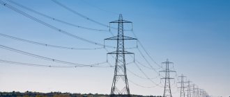
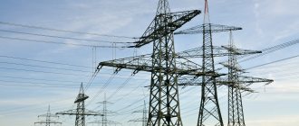
Scope of application and purpose of high-voltage line supports
| Scope of application and purpose of overhead line supports | Length of lines, km | Rated voltage, kV |
| Power supply to individual facilities and consumers in any populated areas; correct distribution of power in enterprises. | Until 3 | Up to 1 |
| Electricity supply to consumers, industrial and rural; energy distribution within large industrial enterprises. | 15 — 3 | 1 — 10 |
| Power distribution in a large populated area; providing electricity to rural consumers. | 30 — 10 | 20 — 35 |
| Redistribution of power within the energy system or electrical network enterprise; supplying electricity to production facilities and hubs in large cities and energy-intensive consumers in rural areas; distribution of power throughout a large city, as well as electrification of pipeline or rail transport. | 100 — 25 | 110 — 150 |
| Power distribution across large energy systems; supplying electricity to consumers who are remote from power systems and power plants; creation of electrical power centers for 110 kV and 150 kV networks; allocation of power to electrical stations that have low power. | 300 — 100 | 220 — 330 |
| Development of integrated energy systems, as well as a unified energy system of the state; ensuring communication between systems; allocation of power by large power stations, as well as supply of electricity to large and energy-intensive enterprises or industrial units. | 1000 — 200 | 400 — 500 |
| Development of large energy systems and creation of a unified state energy system; ensuring connections between systems; allocation of power by large power plants. | 2000 — 300 | 750 |
| Development of large energy systems that are interconnected; creation of a unified state energy supply system; ensuring communication between systems; allocation of power by large power plants. | 3000 — 500 | 1150 |
Power lines have a number of significant advantages:
- The lines simply gather on the track.
- They have relatively low weight and high mechanical strength. If we take into account the same height and load, overhead line supports are two times lighter than wooden ones and eight times lighter than reinforced concrete ones.
- Technologies make it possible to produce double-circuit and multi-circuit supports with a large number of wires and significant height, which are convenient for installation in cramped areas.
The following main types of overhead line supports are distinguished: anchor and intermediate. The difference between these types of supports is the way the wires are suspended.
1. Intermediate transmission line supports are typical for straight sections of high-voltage lines. Their purpose is only to support wires and cables; such supports are not designed to withstand the loads that arise when the wires are tensioned on the line. On the intermediate supports of the lines, the wires are suspended using special garlands of insulators. The distance from the support to the support is called the intermediate span, or simply the span.
Such supports are installed to support wires in anchor spans on straight sections of high-voltage lines. The intermediate support is easier to manufacture and, therefore, cheaper than the anchor support. This is because the tension of the wires on both sides is the same (if the wires are not broken), such a support does not experience forces along the line. 80-90% of high-voltage line supports are intermediate.
Quality control
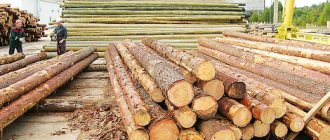
During the manufacturing process, supports undergo several stages of quality control. The first involves examining an element of a future power line for geometric accuracy. After this, the workpiece is sent for drying. Before impregnation, the material is checked for moisture content, which should not exceed 28%. Next, control verification activities are provided, during which the characteristics of the protective agent used to treat wooden power line poles are determined. Installation rules require that the material be delivered to the installation site with an optimally impregnated structure. To comply with this condition, technologists evaluate the depth of impregnation, and based on the results of the analysis, an appropriate quality certificate is generated.
Intermediate transmission line supports for 35-1150 kV overhead lines
Intermediate supports for 35 kV overhead lines
| Name and type | Height to the bottom of the traverse, m | Approximate weight, kg | Approximate weight with zinc coating, kg |
| P35-1V | 15,0 | 1558 | 1623 |
| P35-2V | 14,0 | 1843 | 1920 |
| PS35-4V | 12,5 | 2195 | 2287 |
Intermediate supports for 110 kV overhead lines
| Name and type | Height to the bottom of the traverse, m | Approximate weight, kg | Approximate weight with zinc coating, kg |
| P110-1V | 19,0 | 1 900 | 2 000 |
| P110-1V +4 | 23,0 | 2 400 | 2 600 |
| P110-2V | 19,0 | 2 700 | 2 800 |
| P110-3V | 19,0 | 2 300 | 2 400 |
| P110-4V | 19,0 | 3 200 | 3 300 |
| P110-5V | 19,0 | 2 400 | 2 500 |
| PS110-5V | 15,0 | 2 100 | 2 200 |
| P110-6V | 19,0 | 3 700 | 3 900 |
| P110-6V+6 | 23,0 | 4 400 | 4 600 |
| PS110-6V | 15,0 | 3 300 | 3 400 |
| PS110-9V | 19,0 | 3 000 | 3 100 |
| PS110-10V | 19,0 | 4 800 | 5 000 |
| PUS110-1 | 19,0 | 4 400 | 4 600 |
Intermediate supports for 220 kV overhead lines
| Name and type | Height to the bottom of the traverse, m | Approximate weight, kg | Approximate weight with zinc coating, kg |
| P220-2 | 22,5 | 6 200 | 6 400 |
| P220-2T | 22,5 | 6 300 | 6 500 |
| P220-2T | 27,5 | 7 700 | 8 000 |
| P220-2+5 | 27,5 | 7 600 | 7 900 |
| P220-2 | 17,5 | 5 600 | 5 800 |
| P220-3 | 22,5 | 4 700 | 4 900 |
| P220-3T | 25,5 | 4 800 | 5 000 |
| P220-3+5 | 30,5 | 5 800 | 6 000 |
| P220-5 | 25,5 | 3 400 | 3 500 |
| PS220-1 | 16,5 | 3 100 | 3 200 |
| PS220-2 | 17,5 | 5 500 | 5 700 |
| PS220-3 | 20,5 | 4 000 | 4 200 |
| PS220-5 | 22,5 | 5 600 | 5 800 |
| PS220-6 | 22,5 | 8 500 | 8 800 |
| PS220-7 | 22,5 | 4 300 | 4 400 |
Intermediate supports for 330 kV overhead lines
| Name and type | Height to the bottom of the traverse, m | Approximate weight, kg | Approximate weight with zinc coating, kg |
| P330-2 | 25,5 | 10 000 | 10 400 |
| P330-2+5 | 27,5 | 11 700 | 12 100 |
| P330-2T | 22,5 | 10 300 | 10 700 |
| P330-2T+5 | 27,5 | 12 000 | 12 400 |
| PS330-2 | 17,5 | 9 000 | 9 400 |
| PS330-2T | 17,5 | 9 300 | 9 600 |
| PS330-2 | 25,5 | 6 100 | 6 400 |
| PS330-3T | 25,5 | 6 500 | 6 800 |
| P330-3+5 | 30,5 | 7 500 | 7 800 |
| P330-3T+5 | 30,5 | 7 900 | 8 200 |
| PS330-3 | 20,5 | 5 400 | 5 600 |
| PS330-3T | 20,5 | 5 800 | 6 000 |
| P330-5 | 25,5 | 4 400 | 4 600 |
| PS330-5 | 25,5 | 7 700 | 8 000 |
| PS330-6 | 22,5 | 10 900 | 11 300 |
Intermediate supports for 750 kV overhead lines
| Name and type | Height to the bottom of the traverse, m | Approximate weight, kg | Approximate weight with zinc coating, kg |
| P750 - 1 | 35,0 | 10 200 | 10 500 |
| PP750-1 | 35,0 | 11 200 | 11 600 |
| PP750-1-1 | 33,45 | 11 100 | 11 500 |
| PP750-1-2 | 31,9 | 11 000 | 11 400 |
| PP750-1-2 | 30,35 | 10 900 | 11 300 |
| PP750-1-3 | 28,8 | 10 800 | 11 200 |
| PP750-1-4 | 35,0 | 11 400 | 11 800 |
| PP750-3 | 35,0 | 12 500 | 13 000 |
| PS 750-1 | 35,0 | 20 300 | 21 000 |
| PS750-3 | 35,0 | 20 600 | 21 500 |
Intermediate supports for 1150 kV overhead lines
| Name and type | Height to the bottom of the traverse, m | Approximate weight, kg | Approximate weight with zinc coating, kg |
| POG 1150 - 1 I | 40,0 | 19 000 | 19 500 |
| POG1150-5I | 40,0 | 16 500 | 17 000 |
2. Anchor supports are necessary for rigid fixation of wires in critical sections of a high-voltage line: at the ends of overhead lines, at the intersection of various engineering structures, such as highways, the width of which exceeds 15 m, railways, etc. On straight sections of a high-voltage line, anchor supports with wires suspended on both sides, in normal operation, do not differ in function from intermediate ones. The distance between them is usually called the anchor span. Any anchor supports are initially designed for one-sided tension of wires and cables in the event of a break in the span adjacent to them. Such supports are much more complex in design than intermediate ones, their price is higher, therefore their number on a high-voltage line should be minimal.
3. Corner supports are required in places where the route turns. They perceive not only the loads of intermediate supports, but also the loads of transverse tension of the wires. They are of anchor or intermediate type. If the angle of rotation is small and the load is small, intermediate corner supports for power lines are installed. If the angle exceeds 30°, anchor corner structures are installed, which are more rigid and anchor-type wires are fastened.
Anchor-corner supports for 35 kV overhead lines
| Name and type | Height to the bottom of the traverse, m | Approximate weight, kg | Approximate weight with zinc coating, kg |
| U35-1 | 10,0 | 2 900 | 3 100 |
| U35-1+5 | 15,0 | 4 500 | 4 700 |
| U35-2 | 10,5 | 4 800 | 5 000 |
| U35-2+5 | 15,5 | 6 600 | 6 800 |
| U35-3 | 10,0 | 1 600 | 1 700 |
| U35-3+5 | 15,0 | 2 300 | 2 400 |
| U35-3+9 | 19,0 | 2 800 | 2 900 |
| U35-4 | 10,5 | 2 800 | 2 900 |
| U35-4+9 | 19,5 | 5 100 | 5 200 |
Anchor-corner supports for 110 kV overhead lines
| Name and type | Height to the bottom of the traverse, m | Approximate weight, kg | Approximate weight with zinc coating, kg |
| U110-1 | 10,5 | 5 000 | 5 200 |
| U110-1+5 | 15,5 | 6 400 | 7 000 |
| U110-1+9 | 19,5 | 8 200 | 8 500 |
| U110-1+14 | 24,5 | 11 300 | 11 700 |
| U110-2 | 10,5 | 7 700 | 8 000 |
| U110-2+5 | 15,5 | 9 700 | 10 100 |
| U110-2+9 | 19,5 | 11 300 | 11 800 |
| U110-2+14 | 24,5 | 14 600 | 15 200 |
| U110-3 | 10,5 | 3 200 | 3 400 |
| U110-3+5 | 15,5 | 4 400 | 4 600 |
| U110-4 | 10,5 | 5 200 | 5 500 |
| U110-4+5 | 15,5 | 6 600 | 6 900 |
| US110-5 | 15,5 | 6 700 | 7 000 |
| US110-6 | 15,5 | 10 400 | 10 900 |
| US110-3 | 10,5 | 5 300 | 5 500 |
Anchor-corner power transmission line supports for 220 kV overhead lines
| Name and type | Height to the bottom of the traverse, m | Approximate weight, kg | Approximate weight with zinc coating, kg |
| U220-1 | 10,5 | 8 600 | 8 900 |
| U220-1+5 | 15,5 | 11 000 | 11 500 |
| U220-1+9 | 19,5 | 12 500 | 13 000 |
| U220-1+14 | 24,5 | 16 500 | 17 200 |
| U220-2 | 10,5 | 14 500 | 14 900 |
| U220-2+5 | 15,5 | 17 700 | 18 500 |
| U220-2+9 | 19,5 | 19 500 | 20 200 |
| U220-2+14 | 24,5 | 23 400 | 24 500 |
| U220-2T | 10,5 | 14 900 | 15 500 |
| U220-3 | 10,5 | 7 200 | 7 500 |
| U220-3+5 | 15,5 | 9 700 | 10 100 |
| U220-3+9 | 19,5 | 11 200 | 11 600 |
| U220-3+14 | 24,5 | 15 200 | 15 800 |
| US220-5 | 15,5 | 10 800 | 11 200 |
| US220-5T | 15,5 | 11 300 | 11 800 |
| US220-6 | 15,5 | 18 700 | 19 400 |
| US220-6T | 15,5 | 19 400 | 20 100 |
Anchor-corner supports for 330 kV overhead lines
| Name and type | Height to the bottom of the traverse, m | Approximate weight, kg | Approximate weight with zinc coating, kg |
| U330-1 | 10,7 | 13 100 | 13 600 |
| U330-1+5 | 15,7 | 16 400 | 17 000 |
| U330-1+9 | 19,7 | 19 000 | 19 700 |
| U330-1+14 | 24,7 | 24 300 | 25 200 |
| U330-2 | 10,7 | 22 900 | 23 900 |
| U330-2+5 | 15,7 | 27 500 | 28 600 |
| U330-2+9 | 19,7 | 30 800 | 32 000 |
| U330-2+14 | 24,7 | 37 400 | 39 000 |
| U330-2T | 10,7 | 23 800 | 25 000 |
| U330-2T+5 | 15,7 | 28 400 | 29 500 |
| U330-2T+9 | 19,7 | 31 700 | 33 000 |
| U330-2T+14 | 27,7 | 38 300 | 40 000 |
| U330-3 | 10,7 | 10 500 | 11 000 |
| U330-3+5 | 15,7 | 13 500 | 14 000 |
| U330-3+9 | 19,7 | 16 400 | 17 000 |
| U330-3+14 | 24,7 | 21 500 | 22 300 |
| US330-2 | 19,7 | 31 000 | 32 200 |
| US330-2T | 19,7 | 31 800 | 33 000 |
Anchor-corner supports for 750 kV overhead lines
| Name and type | Height to the bottom of the traverse, m | Approximate weight, kg | Approximate weight with zinc coating, kg |
| US750-1 | 20,0 | 29 500 | 30 500 |
| US750-1+5 | 25,0 | 42 000 | 43 600 |
| US750-1+10 | 30,0 | 47 100 | 49 000 |
| US750-1+15 | 35,0 | 65 000 | 67 600 |
| USk750-1 | 20,0 | 32 300 | 33 600 |
| USk750-1+5 | 25,0 | 44 800 | 46 500 |
| US750-1+5t | 25,0 | 44 800 | 500 |
Features of supports SV 95-2, SV 95-3, SV 95-3s
Before moving on to the varieties themselves, it is worth finding out what the marking of the SV 95 racks itself means. “SV” stands for vibrating rack, and the numbers 95 indicate the length of the rack in decimeters. Among the SV 95 supports, it is worth highlighting 3 varieties:
- SV 95-2.
These supports are used for laying lines whose voltage reaches 0.38 kV. The mass of one support unit is 0.75 tons, the bending moment is 2.0 tf*m. - SV 95-3.
These racks can be used during the construction and reconstruction of power lines. The mass of these racks is greater - 0.90 tons, since they have higher strength and a higher bending moment - 3.0 tf*m. The number of supports available for transportation in a 20-ton vehicle is 22 units. - NE 95-3s.
These racks are also used during the construction and restoration of power lines, but they differ from the previous type of supports, the SV 95-3s racks in that they have a lower mass - 0.75 tons, their bending moment is identical - 3.0 tf*m, but maximum load in a vehicle is 20 tons more - 27 units.
Free-standing anchor-corner power transmission line supports
Anchor-corner free-standing supports for 110 kV overhead lines
| Name and type | Height to the bottom of the traverse, m | Approximate weight, kg | Approximate weight with zinc coating, kg |
| US110-7 | 10,5 | 7 400 | 7 700 |
| US110-7+5 | 15,5 | 9 400 | 9 800 |
| US110-7+9 | 19,5 | 11 000 | 11 500 |
| US110-7+14 | 24,5 | 14 400 | 15 000 |
| US110-8 | 10,5 | 12 000 | 12 500 |
Anchor-corner free-standing supports for 500 kV overhead lines
| Name and type | Height to the bottom of the traverse, m | Approximate weight, kg | Approximate weight with zinc coating, kg |
| U1 | 17,0 | 14 200 | 14 800 |
| U2 | 17,0 | 15 300 | 16 000 |
| U2k | 17,0 | 16 500 | 17 200 |
4. Transient power transmission line supports are erected if high-voltage lines cross over engineering structures or natural barriers. This type of support can withstand the heaviest loads, and their height can be equal to the height of a building of twenty-five floors.
Transition supports for 220 kV overhead lines
| Name and type | Height to the bottom of the traverse, m | Approximate weight, kg | Approximate weight with zinc coating, kg |
| PP220-2/40 | 40,0 | 50 000 | 52 000 |
| PP220-2/50 | 50,0 | 60 000 | 62 500 |
| PP220-2/60 | 60,0 | 70 000 | 73 000 |
| PP220-2/70 | 78,0 | 80 000 | 84 000 |
Transition supports for 330 kV overhead lines
| Name and type | Height to the bottom of the traverse, m | Approximate weight, kg | Approximate weight with zinc coating, kg |
| PP330-2/40 | 40,0 | 91 000 | 93 500 |
| PP330-2/50 | 50,0 | 106 500 | 110 000 |
| PP330-2/60 | 60,0 | 123 000 | 128 000 |
| PP330-2/70 | 70,0 | 143 000 | 147 500 |
| PP330-1/41 | 41,0 | 65 000 | 67 500 |
| PP330-1/51 | 51,0 | 78 500 | 81 000 |
| PP330-1/61 | 61,0 | 95 000 | 99 000 |
| PP330-1/71 | 71,0 | 112 500 | 116 000 |
| PP330-1/81 | 81,0 | 132 000 | 137 000 |
Reinforced concrete structures as an alternative
It should be noted right away that from the point of view of operation it is more profitable to use reinforced concrete structures. They are more reliable in all technical parameters, but, of course, they cost much more. In turn, wooden power transmission line supports, even in the best designs, can only approach the characteristics of reinforced concrete structures with varying degrees of success. This material, even with high-quality impregnation, will not be able to last as long as a concrete structure. However, the low service life is offset by the cost. Regular replacement of pillars at intervals of at least 5 years is well within the budget for the use of reinforced concrete analogues.
Delivery
We not only produce high-quality products, but also deliver them throughout Russia by road!
We will take care of all your delivery concerns:
- We will issue a transportation permit
- Let's order an escort car
- Let's agree on the route
- We will agree with the transport company
- We will control the delivery from the loading point to the unloading point
- We will take responsibility for the safety of the cargo in transit
