Electrical overhead lines (OHLs) are now mainly built using insulated self-supporting wire. Its distinctive feature is the presence of surface insulation made of thermoplastic or cross-linked lightproof polyethylene, which makes the operation of lines and bends safer.
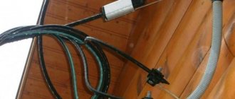
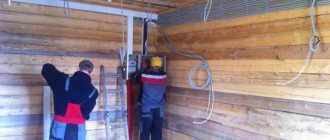
Let's look at how SIP installation is carried out as part of the arrangement of electricity input into the building.
Inserting wires into a residential building Source izion.pro
Structural differences of SIP
In networks with voltages up to 1 kV, only two types of insulated wires are used, although there are more of them. To understand what the difference is between them, we have provided a small informational list:
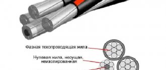
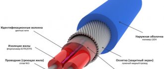
SIP – 1 Source 1sip-kabel.ru
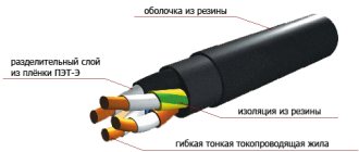
- SIP-1 is a bundle of twisted phase wires with insulation and one uninsulated neutral conductor made of high-strength ABE alloy. Has from one to four conductive cores.
SIP – 2 Source provodok.site
- A distinctive feature of SIP-2 is the presence of insulation not only on the phase wires, but also on the neutral core, and naturally, it has a higher cost. That is why it is used mainly on high-voltage lines.
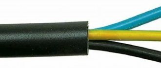
SIP – 4 Source promkabel.org
- This type of wire has at least two current-carrying wires, but it does not have a carrier (zero) wire. It is designed specifically for making branches from power lines towards buildings and laying along walls.
Note! Other types of SIP differ from each other not only in the type of insulation, but also in the number of cores. However, to carry out electrical inputs into the house, only SIP-1 and SIP-4 are most often used - the rest are intended for lines with voltages up to 35 kV.
Due to the presence of insulation, the SIP wire has an aesthetic appearance. This is, of course, an important nuance - but more for the consumer. Energy supply organizations value SIP because the insulation does not allow for “throwing” onto the wire, and thus using the resource bypassing metering devices. Another advantage is that the sheath makes it possible to connect two wires to each other without removing the voltage from them - however, this requires special fittings.
Next, let's look at how to connect the SIP cable to each other and perform any other manipulations with it.
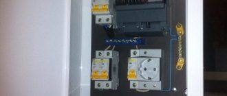
Selection and calculation of the introductory machine
To protect the input cable, we need to select a circuit breaker for input into the house, which is selected according to the rated current flowing through it when consumers are turned on. In order to determine the rated current of the input circuit breaker, it is necessary to calculate the total power of all consumers in the house. We have compiled a table showing the name and power of the consumer
| electrical appliance | Power, W |
| LCD TV | 200 |
| Fridge | 600 |
| Boiler | 2000 |
| Iron | 1500 |
| Electric kettle | 1800 |
| Microwave | 1000 |
| Computer | 500 |
| Lighting | 800 |
| Well pump | 1000 |
| Air conditioner | 400 |
| Total | 9800 |
But since consumers cannot all be turned on at the same time, the demand coefficient is used for calculations, which is equal to 0.7 when the number of receivers in the room is from 5 to 200.
Using the formula, we determine the estimated total active power of consumers:
Calculation of active power of all consumers
Next, you need to calculate the total total power of consumers in the house using the following formula:
Calculation of the total power of all consumers
where cos phi is the power factor, for residential premises it lies in the range of 0.96 - 0.98.
Now we determine the calculated current for a single-phase network using the following formula
Rated current calculation
where Unom is the rated voltage of a single-phase network equal to 220 V
Now, based on the calculated current, we select the rating of the input circuit breaker. For internal power supply of apartments and houses, modular circuit breakers of standard ratings are used:
6, 10, 16, 25, 32, 40, 50, 63 A
The rated current of the machine must be equal to or the nearest greater from the standard range.
In our case, for an introductory machine, we need a machine with a rated current of 32 A
Diversion of SIP from overhead lines to the house
In order to connect a SIP wire from a pole to a house, you need to accurately measure the distance to the nearest support. If it exceeds 25 meters, you will have to install an additional power pole - perhaps right in the yard.
Maximum distance to the nearest pole Source fs137.myvi.tv
If the standard is met, you can lay the wire directly from the street support. Let's figure out what is needed for this.
Required fittings
To carry out installation work, the following fittings are required:
Branch (piercing) clamp with protective cap Source static-eu.insales.ru
- The number of clamps corresponds to the number of current-carrying cores of the wire.
Anchor clamp Source must.su
- To install a SIP cable from a pole to a house, you need 2 clamps, and two more for an additional branch support, if one is installed.
Steel fastening tape (bandage) Source kvt-pro.ru
- A galvanized steel tape is used to secure the SIP to the power line pole. One support requires 1 meter of tape.
Book clip Source infoyar.ru
- Reinforced clamps (buckles) are used to fix the steel bandage. There are 2 pieces per bracket.
Bracket Source dixi-st.com
See also: Catalog of flat roof house projects
- To secure the branch wire to the support, you will need 2 or 4 brackets. They are attached to the pole with tape, and to the facade of the building with anchors.
Strap (tightening clamp) Source svetelektro.net
- It takes 5 straps to make one connection.
Fastening Source stofasadov.ru
- Fastening SIP to the wall of a building is carried out using this simple device. Installed at 70 cm intervals, so the quantity is calculated based on the total length of the input.
Process in action
Now let’s illustrate how all this comes together into a single structure.
Installing anchors and pulling wires
It is impossible to drill an electrical support, so to install the brackets, not anchor bolts are used here, but bandage tape. It is wrapped in two rows around the post and secured with paper clips (buckles).
Attaching the bracket to the pole using tape Source youtube.com
- Then the wedge, which is shown in the photo with a red arrow, is removed from the anchor clamp, the wire is pulled through it and the wedge is inserted back.
Pulling the wire through the anchor clamp Source youtube.com
- Now, using the clamp fork, the wire is fixed to the bracket.
Installation of SIP on supports using an anchor clamp Source youtube.com
See also: Catalog of companies that specialize in electrical work and related services
- To connect to an overhead line, you need to install branch clamps with one side on the main wire, and the other on the wire that will go to the house. The arrow in the picture shows the central bolt. It must be tightened with a spanner until it comes off.
Installation of branch clamps Source youtube.com
- Protective caps are put on the exposed ends of the wires, and the wire strands are tightened with a clamp.
Wire lugs Source youtube.com
- The wire is thrown towards the house, where a bracket is also installed to secure it. Only here it will be fixed not with a bandage, but with bolts.
Mounting the bracket to the facade Source youtube.com
Note! The height of the wire to the building according to SNiP is 2.75 m, but if the house itself does not meet this parameter, the entry can be made through the roof.
The type of anchors for installation on the facade is selected based on the wall material. After securing the bracket, an anchor clamp with a wire threaded into it is attached to its eye in the same way as was done at the opposite end. The clamp must be installed so that the wire between the pole and the wall of the house is tensioned and not sagging.
Attaching the wire to the facade Source youtube.com
Important! The wire is tensioned using a hand winch, which has a mechanism for capturing and compressing the load-bearing core or the entire bundle. The force applied to the wire must be accurately measured, for which a dynamometer is used. If work is carried out according to a project, then data on the tension force is taken from it. In the absence of regulatory documentation, the amount of force that must correspond to the cable brand and its span between the anchors can be taken from the installation table.
If the distance of the nearest VLI pole to your house was more than 25 meters and you had to install an intermediate support, the wire will be attached to it as shown in the picture below.
Attaching SIP to an intermediate support Source youtube.com
Selection and calculation of input cable
The aluminum cable AVVG 2x10 mm2 was mentioned above, perhaps you were wondering where the figure came from? Everything is very simple, before purchasing we made a preliminary calculation of this conductor.
The cross-section of the cable for entry into the house is calculated based on the maximum permissible current at which heating of the conductor will not cause damage to the insulation of the input cable.
Those. our cable must withstand the current for a long time at which the thermal release of the machine will operate.
The thermal release current is assumed to be 15-20% greater than the rated current of the machine and is calculated using the formula:
Calculation of thermal release current
Now from the PUE, in tables 1.3.4 for copper conductors and 1.3.5 for aluminum conductors, we select the required cross-section of the cable laid in one pipe from the “ one two-core ” column, equal to or the nearest larger.
Table 1.3.4. Permissible continuous current for wires and cords with rubber and polyvinyl chloride insulation with copper conductors
| Cross-section of current-carrying conductor, mm2 | Current, A, for wires laid | |||||
| open | in one pipe | |||||
| two single-core | three single-core | four single-core | one two-wire | one three-wire | ||
| 0,5 | 11 | — | — | — | — | — |
| 0.75 | 15 | — | — | — | — | — |
| 1 | 17 | 16 | 15 | 14 | 15 | 14 |
| 1,2 | 20 | 18 | 16 | 15 | 16 | 14,5 |
| 1,5 | 23 | 19 | 17 | 16 | 18 | 15 |
| 2 | 26 | 24 | 22 | 20 | 23 | 19 |
| 2,5 | 30 | 27 | 25 | 25 | 25 | 21 |
| 3 | 34 | 32 | 28 | 26 | 28 | 24 |
| 4 | 41 | 38 | 35 | 30 | 32 | 27 |
| 5 | 46 | 42 | 39 | 34 | 37 | 31 |
| 6 | 50 | 46 | 42 | 40 | 40 | 34 |
| 8 | 62 | 54 | 51 | 46 | 48 | 43 |
| 10 | 80 | 70 | 60 | 50 | 55 | 50 |
| 16 | 100 | 85 | 80 | 75 | 80 | 70 |
| 25 | 140 | 115 | 100 | 90 | 100 | 85 |
Table 1.3.5. Permissible continuous current for rubber and polyvinyl chloride insulated wires with aluminum conductors
| Cross-section of current-carrying conductor, mm2 | Current, A, for wires laid | |||||
| open | in one pipe | |||||
| two single-core | three single-core | Four single-core | one two-wire | one three-wire | ||
| 2 | 21 | 19 | 18 | 15 | 17 | 14 |
| 2,5 | 24 | 20 | 19 | 19 | 19 | 16 |
| 3 | 27 | 24 | 22 | 21 | 22 | 18 |
| 4 | 32 | 28 | 28 | 23 | 25 | 21 |
| 5 | 36 | 32 | 30 | 27 | 28 | 24 |
| 6 | 39 | 36 | 32 | 30 | 31 | 26 |
| 8 | 46 | 43 | 40 | 37 | 38 | 32 |
| 10 | 60 | 50 | 47 | 39 | 42 | 38 |
| 16 | 75 | 60 | 60 | 55 | 60 | 55 |
| 25 | 105 | 85 | 80 | 70 | 75 | 65 |
According to the tables, cable cross-sections are suitable for us: 6 mm2 for a copper conductor and 10 mm2 for an aluminum conductor.
Installation sequence
When tightening the shear nut, such force must be applied that the clamp teeth:
- did not damage the main core of the SIP
- pierced but did not cut the insulation
- retained the load-bearing capacity of the core at 80% of the original
Ensto products, thanks to the pyramidal shape of the teeth and their staggered arrangement, do this better than many others.
You can see tensile testing of SIP after its cores have been pierced with clamps of different brands.
At the end, the connected soldered SIP is bent to the main one and pulled to it with a tie. This is done so that in the wind the contact is not subjected to mechanical stress and does not break off in the future.
Safety Compliance
In any option (either on your own or with a hired team) of building a line, you must follow the safety instructions:
- It is prohibited to carry out installation work when a thunderstorm is approaching or during strong winds (speed more than 12 m/s);
- It is unacceptable for installers to be under working cradles or telescopic towers;
- It is prohibited to use a combined method of installing supports (manually and mechanically);
- It is not allowed to use damaged devices and cables when installing supports;
- in cases where it is necessary to hold the load suspended, it is necessary to securely fix the lifting mechanisms (with brakes and jamming of gears);
- climbing onto wooden supports is permitted only with the help of a fitter’s claws or special devices;
- when performing work on supports, the installer should stand on two claws at the same time;
- The installer must not be positioned on anchor supports or under wires during work;
- It is prohibited to throw tools to the installer;
- It is allowed to supply tools and materials using a rope with a length of at least double the lifting height;
- It is unacceptable to carry out tensioning work at temperatures above minus 20 ºС;
- during work, it is necessary to observe the installation efforts and control the sag of the wires;
- do not over-tension the line;
- control the installation process and carry out step-by-step acceptance of work.
The channel Sami with a Mustache will tell you how to choose a SIP cable.
Changing the contact surface of the core
Another option is to strip the SIP core with a small margin. Then, using pliers, twist the end of the exposed core even further, creating, as it were, one whole of many cores. This results in a smoother, more twisted section of the veins. And connect it directly to the contact of the modular machine.
In an automatic machine, such twisting does not separate into separate wires and the contact seems to improve. But again, in terms of useful compression area, this method is not the best. And if you use the load to the maximum, then after a certain time, although longer than in the first option, the contacts will still have to be tightened.
You can simply, without even bothering, screw a separate 2.5 mm2 core bandage onto a bare area and put it into the machine.
Wire rolling
The installation of SIP begins after installing the VLI supports with clamps attached to them.
Anchor clamps are installed on the anchor supports that carry the tension force of the conductors, and supporting clamps are installed on the intermediate supports located between them.
Installation of SIP cable begins with its unrolling. To do this, perform the following steps sequentially:
- Special unrolling rollers are installed on all supports of the anchor span on which the wire is mounted. On the extreme, anchor supports, the rollers are fastened with a belt; on the intermediate supports, the rollers are suspended on a hook in the eyes for supporting clamps;
- A drum with wire is installed behind one of the outer supports of the span. It is located in a vertical position on special stands that allow it to rotate during the rolling process. In order for the wire to enter the roller at a flatter angle, it is recommended to install the drum from the support at a distance not less than its length;
- On the other side of the mounted span there is a drum on which a leader cable is wound, usually a synthetic rope with a diameter of 10–12 mm, depending on the rolling method (manual, mechanized);
- Next, the leader cable is rolled out manually. This operation is performed by sequentially lifting onto each support, threading the cable into the roller and further pulling it;
- After lifting to the last support, the leader cable is connected to the SIP using a special stocking and swivel that prevents the wire from twisting during the rolling process.
This is where the preparatory procedures end, and the actual rolling out of the wire begins. The leader cable slowly, without jerking, is pulled in the opposite direction. During mechanized rolling, the drum winding device is driven by an internal combustion engine with a gearbox; the leader cable can also be pulled out manually.
During the rolling process, the wire, following the leader cable, rises to the support and takes its place on the rollers. Rollers and drums must be located so that when rolling there is no friction of the wire on the ground, support and other structures. It is unacceptable to use a technology in which the wire is rolled out on the ground and then lifted onto a support.
Security measures
Before securing the wire, you should stock up on a mounting belt. There must be people nearby for backup. Work is carried out only in dry weather.
To carry out the work, you need to wear long sleeves and pants. Shoes should have good rubber soles.
The voltage must be turned off; if it is present, installation work can be life-threatening. Before lifting onto the support, you should check its stability; do not grab the pins and hooks present on the support.
When choosing a ladder, you need to pay attention to the fact that its length does not exceed 5 meters, and the angle of inclination is from 70 to 75 degrees. When working from a cradle, be sure to wear a helmet and a fastened belt.
Note! If you manage to turn off the power, you need to post a warning sign and close the substation or switchboard. Next, you should check the absence of voltage using a probe
In conclusion, it should be noted that SIP grade material is the next generation of wires for overhead power lines, significantly increasing the efficiency of their operation. In domestic use it is mainly used when laying lines from the transformer to the consumer and making branches from them. One of the main advantages when using it is the ease of installation and operation, which allows a person to operate it without much experience in such work. But in any case, we must remember that qualified electricians must install and extend electrical wiring to the network.