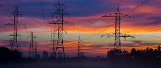
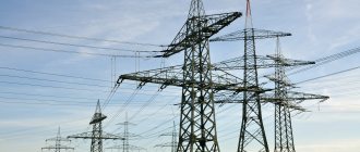
Overhead power transmission towers are an integral part of energy systems that are needed by all types of civil, military, and industrial facilities. In the complex of residential low-rise and high-rise construction, during the construction of industrial facilities, infrastructure is planned and built, which includes power lines, substations and supports. The durability of the power transmission line structure, its strength, and resistance to a number of external mechanical and natural factors depend on the choice of type and type of supports. Reliable supports, in turn, guarantee trouble-free power supply to infrastructure facilities, excluding interruptions and the occurrence of emergency situations. Modern standardized supports allow the construction of reliable overhead power lines in a short time in different climatic zones, on soils of different bearing capacity.
Types and purpose of power transmission line supports
All existing types of structural products that serve as supports perform the function of supporting overhead power line wires. Depending on the line voltage, there are supports designed for 220V, as well as 0.4, 6, 10, 35, 110, 150, 220, 330, 400, 500, 750 and 1150 kV. In this case, air lines are divided into three categories:
- from 0.4 to 10 kV;
- from 35 to 110 kV;
- from 220 to 330 kV.
The distance between the supporting elements of a power transmission line structure is called the span. The higher the operating voltage of a high-voltage line, the longer its crossarms, the larger the dimensions and weight of the structure.
In this case, the design of the support posts must provide the ability to install:
- cable terminations;
- protective switches and devices;
- panels and cabinets for connecting individual electrical receivers;
- switching and sectioning devices;
- street lighting fixtures of any design.
Based on the method of fastening, a distinction is made between supports that can be installed directly on the ground, as well as elements for the installation of which it is necessary to build a special foundation. The latter are divided into classic and narrowly basic. In its usual form, the width of the mounting base has an area of more than 4 m2, providing for frame, frame or poured foundations. The narrow base category includes all bases whose area is less than 4 m2. Often such fastenings involve the installation of a reinforced concrete or screw pile, a steel pipe and are used in areas with limited space.
Depending on the type of fastening, the supports can be differentiated into upright and guyed structures. The latter are the most stable and durable, requiring additional work on the installation of guys and their fastening, each of which must have its own separately formed foundation.
Metal, reinforced concrete, wood and composite supports - advantages and disadvantages
Depending on the material used, supports are made of:
- wood;
- reinforced concrete;
- become.
Currently, there are also composite type supports that include elements from various materials. For example, reinforced concrete can be assembled with metal tips, ribs, and posts to form the required configuration and size.
Each type of support elements has a set of individual characteristics that must be taken into account when designing and installing on site.
Reinforced concrete supports are made of concrete, which is reinforced with metal to enhance strength. In order to increase reliability for lines from 35 to 110 kV, centrifugation technology is used during production, with the help of which the concrete mixture is compacted as much as possible, eliminating air layers that reduce strength. During the production process, the solution is poured into special metal molds, inside of which there is a pre-created reinforced frame of transverse and longitudinal rods. Reinforced concrete products are resistant to external influences and corrosion. The chemical inertness of concrete does not allow it to interact with chemical elements, allowing operation in aggressive environments and reagents with which the air can be saturated. One of the main disadvantages of such supports is their high weight, which makes delivery difficult and places demands on the installation process and the quality of the prepared base. At the same time, reinforced concrete is characterized by a high degree of durability, which guarantees trouble-free operation of supports over a long service life, which is at least 60 - 80 years.
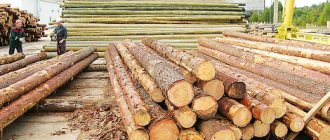
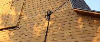
Wooden poles for power lines are made from solid logs. Most often, their use is relevant for low-voltage overhead lines with a voltage of 220 or 380 V. The material used in the production of supports is predominantly coniferous wood, less often deciduous. One of the main advantages of using wooden wire fastening elements is its affordable cost. in the presence of local types of wood, this allows for significant savings in the construction and laying of power lines. At the same time, such supports are inferior in durability to metal, reinforced concrete and composite products. During operation, wood is destroyed under the influence of sunlight, moisture, the parasitic influence of insects, due to seasonal temperature changes and other natural factors. In order to increase their service life, wooden logs are treated with special compounds. Mastics and resins can extend the durability of products to 20–25 years in the most favorable conditions. Wooden supports are used for the construction of A- and U-shaped structures.
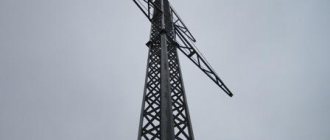
Metal support products for power lines are made from steel alloys of established grades. Separate structural components, representing load-bearing elements and stiffeners in the form of beams and corners, are connected together. For this purpose, a welded rigid connection is used, which provides connection of surfaces at the molecular level or a prefabricated connection using bolts and nuts. In order to prevent a decrease in the strength of metal supports due to corrosion, galvanized rolled steel is often used. Some structures are painted with special protective compounds. Depending on the design features, the following types of steel supports are distinguished:
- lattice;
- multifaceted.
In addition, support structures made from closed and open profiles are distinguished. The former include hexagons and octahedrons, the latter triangles and products with a square section. Also, pipes are often used as a basis for the construction of steel supports for power lines.
Composite types of supporting elements are a new type of structures that incorporate individual units made of various materials.
Terms and Definitions
Power line support (PTL) is a structure designed to hold wires and, if available, lightning protection cables for overhead power lines and fiber-optic communication lines at a given distance from the surface of the earth and from each other.
Intermediate power line supports are structures installed on straight sections of power lines and designed only to support wires and cables at a certain level. Not designed for loads directed along the route.
Intermediate straight power line supports are structures installed on straight sections of overhead lines to support the wire in the anchor span.
Intermediate corner power line supports are structures installed at the turning points of the line, used to compensate for the total lateral loads from the tension of the wires when the route turns .
Anchor supports for power lines are structures on straight sections of power lines at places of transition through engineering structures or natural barriers to limit the anchor span, as well as in places where the number, grades and cross-sections of wires change.
Anchor-corner power transmission line supports are structures used for the construction of overhead lines in areas with various ice and wind loads and designed for small rotation angles and small grades of wires.
Power line end support is a structure that is a type of anchor support and is installed at the end and beginning of a power transmission line. Designed to withstand the load from one-sided tension of all wires and cables.
Lattice power line supports are structures used in the construction of overhead lines with a voltage of 35-1150 kV and intended for installation in populated and uninhabited areas in IV climatic icy and windy regions, where the ambient temperature does not fall below -65°C.
Anchor-corner metal supports for 35 kV overhead lines are single-column free-standing structures used for the construction of 35 kV overhead lines in areas with various ice and wind loads.
Anchor-angle steel power transmission line supports are special steel structures with horizontal wires, designed for use in urban environments.
Transition metal supports for power transmission lines of 110 kW overhead lines are single-column, free-standing structures used for the construction of overhead lines up to 110 kV in areas with various ice and wind loads.
Metal lattice transmission line supports are structures used in the construction of overhead lines with a voltage of 35-1150 kV and are intended for installation in populated and uninhabited areas in IV climatic icy and windy regions, where the ambient temperature does not fall below -65°C.
Unified lattice transmission line supports are structures used in the construction of overhead lines, which are made in the form of spatial lattice structures and are assembled from a large number of elements made of rolled angle steel.
Transient power line supports are structures used to cross overhead lines through natural barriers and engineering structures.
Transposition transmission line supports are structures used to change the order of arrangement of wires on the supports.
Branch power line supports are structures used to make branches from the main overhead line.
Power transmission line supports for large crossings are structures used in the construction of overhead lines across rivers and water bodies, etc.
Cross power transmission line supports are structures used to implement the intersection of two overhead lines.
Overhead line supports with guy wires are structures used to compensate for the forces arising from the tension of wires when turning and ending the power line route.
Free-standing single-post metal power transmission line supports are structures based on steel polyhedral posts and have a flange connection to the foundation.
Steel multifaceted power transmission line supports are structures used for the construction of overhead power lines and designed to support overhead power line wires with a voltage of 10-500 kV. Installed in populated and uninhabited areas in IV icy and windy areas, where the air temperature can drop to -65°C.
Steel lattice transmission line supports are spatial lattice structures made of low-alloy rolled steel grade 09G2S or carbon steel grade St3 with anti-corrosion treatment by hot-dip galvanizing or coating with a special zinc-filled composite.
Steel transmission line supports made of bent profile are spatial structures used when laying overhead lines to increase reliability, reliability, durability and reduce operating costs, especially in hard-to-reach areas with severe climatic conditions.
Single-circuit power transmission tower supports are T-shaped structures tapering upward with one traverse, used for the construction of high-voltage direct current lines.
Portal power line supports are structures made of metal, wood or reinforced concrete, resembling the letter “P” or the letter “N”. They are widely used on 330-750 kV power lines. As a rule, single-chain.
AP-shaped power transmission line supports are single-circuit spatial structures created using welded metal pipes, MGS or wood, resembling the letter “A” in profile and the letter “P” in front. The cross-section of pipes in these supports can reach 1300 mm, and the height can be over 80 m.
Three-post separate lattice power line supports are spatial metal structures used as anchor supports for the construction of overhead lines at turns and transitions.
L-shaped power transmission line supports are flat L-shaped lattice structures, articulated with two foundations, used as transition lines for two 110 kV or 220 kV overhead line circuits.
Y-shaped single-chain supports are metal spatial lattice-type structures. Used as transitional supports for overhead lines.
V-shaped intermediate pores of power lines are spatial structures of the “Nabla” type with guys, used on power line routes of 330-1150 kV. Exclusively single-chain.
Power transmission line poles are spatial structures of a non-lattice type, based on wooden, metal or reinforced concrete poles. There are single-post and portal ones. structures that serve to support live wires and lightning protection cables above the earth's surface.
Portal pole supports for power transmission lines are spatial structures consisting of two poles (wooden, reinforced concrete or MGS) connected by a common traverse.
Intermediate supports with internal connections are structures used in the construction of overhead lines that have internal fixed connections connecting several support elements to each other.
Intermediate transitional power transmission line supports are steel structures for the construction of overhead lines up to 330 kV in areas with various ice and wind loads. These supports are produced as single-column free-standing ones.
Multifaceted supports of a closed profile - steel structures of a closed profile (six-, eight-, etc. edges), galvanized by hot-dip galvanizing, with bored and sheet-pile foundations.
Multifaceted open profile supports are open profile steel structures (triangular and square cross-section), galvanized by hot-dip galvanizing, used for the construction of overhead lines.
Wooden power line poles are pine and larch round logs impregnated with an anti-rot compound (antiseptic), used for lines with voltages up to 220/380 V.
Composite power line supports are building structures made of reinforced polymer composite materials, designed to hold wires and lightning protection cables at a given distance from the ground and from each other.
Cable-stayed emergency reserve supports are V-shaped structures on guys with a cable-stayed polymer traverse, used for the prompt elimination of technological violations on power lines.
Mobile power transmission line supports are prefabricated structures for the construction of overhead lines, which can be assembled without the involvement of teams of workers and without preparing the foundation.
Narrow-base power transmission line supports are a structure no more than 4 meters high for laying overhead lines, installed in the foundation with fastening to a steel pipe or steel screw or reinforced concrete pile.
Power transmission line branch supports are metal structures used to organize branches from overhead lines.
Vibrated reinforced concrete posts for power transmission line supports are elements of power transmission line supports that are made from both prestressed and non-stressed reinforced concrete in multi-place rectangular formwork using vibration and heat treatment.
Centrifuged reinforced concrete racks for power transmission line supports - conical with a slope or cylindrical reinforced concrete structures of annular cross-section, manufactured by rotation in special forms.
Swinging transition supports for power transmission lines are flat L-shaped structures, hingedly connected to two foundations, used for laying overhead lines.
Classic tower supports for power transmission lines are spatial structures used on both single-circuit, double-circuit and multi-circuit crossings of lines.
Elevated linear power line supports are structures that have special supports at the base. Used for short transitions.
Three-post power transmission line supports are structures that have three posts, each of which is designed for hanging wires of one phase.
Power line supports based on polyhedral bent posts (MGS) are spatial structures of a transitional type, made of multifaceted bent posts. Can be U-shaped or tower.
High-voltage cross-beams are gripping devices used for installing pin and suspension insulators and fastening insulated and non-insulated wires, installing disconnectors on 6-10 kV overhead lines and switchgear in populated and uninhabited areas.
Low-voltage traverses TM are the main load-bearing elements of overhead line supports, used for installing pin and suspension insulators and fastening insulated and non-insulated wires, installing disconnectors on overhead lines and switchgear 6-10 kV in populated and uninhabited areas.
High-voltage crossbeams TV, V, B - steel elements in the supports of 35 kV and 110-220 kV overhead lines.
High-voltage extensions TS are devices intended for use in transition supports for 6-10 kW overhead lines. They allow you to increase the height of standard reinforced concrete racks to organize the safe passage of power lines through various engineering structures, including other overhead lines with insulated and non-insulated wires.
Exhaust overlays and headbands in power transmission line supports are devices designed for installing insulators of the upper single or double wire or insulating pendants on reinforced concrete supports of 6-10 kV overhead lines in populated and uninhabited areas.
Brackets and assemblies for fastening slopes in power transmission line supports are connecting elements used in the construction of corner, transition, branch and end supports with struts based on reinforced concrete racks of trapezoidal cross-section and serve for reliable fastening of the strut to the support rack, transmission and distribution of existing horizontal loads between the connected load-bearers designs.
Power line support tie-downs are elements used for the installation of corner, transition and end supports based on SV164 reinforced concrete pillars, to compensate for the forces arising from the tension of wires when turning and ending the power line route.
Pins for supports are connecting elements used to attach pin insulators to the cross-arms of power transmission line supports.
Support clamps are metal elements for power transmission line supports, made of carbon steel with corrosion protection and galvanized or painted.
An A-frame drop boom is a structure used to lift and install assembled power transmission towers from a horizontal to a vertical position by rotating around the hinge of the mounting boom connected to the poles being mounted.
Reinforced concrete foundations for power transmission line supports are standardized foundations used when installing power line supports with voltages of 35-500 kV.
Unified foundations for 35-500 kV transmission line supports are a mushroom-shaped monolithic foundation with a vertical or inclined post or with hanging slabs.
The foundations of metal supports for overhead lines are monolithic footboards in formwork. They can have a vertical or inclined stand.
Crossbars for overhead line supports are structural elements of power transmission line supports used to improve the ability of the foundation to withstand horizontal loads.
Wire sag - vertical distance from the line connecting the wire suspension points on adjacent air supports. Power lines, to the lowest point of the wire. If the suspension points have different heights, then two S. points f1 and f2 are determined. For air lines with a voltage of 35-110 kV S.p. is 3 - 4 m, for lines 500 - 750 kV - 7 - 8 m.
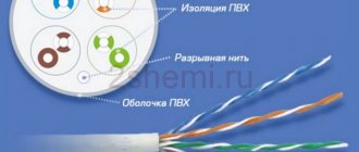
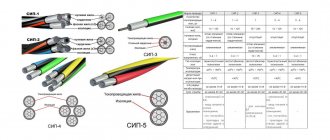
Wire for overhead power lines - self-supporting insulated and protected wires for overhead power lines.
Lightning protection cable is a cable lightning rod, a grounded wire in overhead power lines, used to protect current-carrying wires from direct lightning strikes.
A power line arrester is a device for closing electrical circuits by means of an electrical discharge in a gas, vacuum or (less commonly) a solid dielectric; contains 2 (or more) electrodes separated (respectively by one or more) discharge gap, the conductivity of which changes sharply when the potential difference between the electrodes becomes equal to a certain value determined under given conditions - the breakdown voltage, or ignition potential.
Overhead power lines are spatial structures in which wires are suspended above the ground or above water.
Overhead line (OL) is a device for transmitting electricity through wires located in the open air and attached to supports using insulators and fittings.
An anchor span is the distance between two overhead line anchor supports on which the wires are rigidly fixed.
Wire is an overhead line element designed to transmit electric current.
Wire (cable) tension is the force directed along the axis of the wire (cable), with which it is stretched and secured to the overhead line anchor supports.
The dimension of the overhead line is the distance from the lowest point of the wire sag to the surface of the earth.
Wire sag (f) is the vertical distance between the straight line connecting the wire suspension points and the lowest point of its sag.
Overall wire sag (fgab) – the largest wire sag in the overall span.
Overhead line span is the distance between adjacent supports of overhead power lines.
Overall span (lgab) – a span, the length of which is determined by the normalized vertical distance from the wires to the ground when installing supports on a perfectly flat surface.
Weight span (lweight) is the length of the overhead line section, the weight of the wires (cables) of which is perceived by the support.
Wind span (lwind) is the length of the overhead line section from which the wind pressure on the wires and lightning protection cables is perceived by the support.
Vibration of wires (cables) - periodic vibrations of a wire (cable) in a span with a frequency from 3 to 150 Hz, occurring in a vertical plane in the wind and forming standing waves with a swing (double amplitude) that can exceed the diameter of the wire (cable).
Dance of wires (cables ) - stable periodic low-frequency (0.2 - 2 Hz) oscillations of a wire (cable) in a span with one-sided or asymmetrical deposition of ice (wet snow, frost, mixture), caused by wind speeds of 3 - 25 m/s and forming standing waves (sometimes in combination with traveling ones) with the number of half-waves from one to twenty and an amplitude of 0.3.
A garland of insulators is a device consisting of several suspended insulators and linear fittings, movably connected to each other.
Linear fittings for overhead lines are, in particular, elements for fastening insulators, protective equipment, clamps, and spiral ties.
Normal overhead line mode is the state of the overhead line with intact wires or cables.
Emergency mode of an overhead line is the state of an overhead line with broken wires or cables.
Installation mode of overhead lines - the state of overhead lines when installing supports, wires or cables.
The overhead line route is the position of the overhead line axis on the earth’s surface.
Cable fastening is a device for attaching lightning protection cables to an overhead line support; if the cable fastening includes one or more insulators, then it is called insulated.
An electrical network is a set of overhead and cable power lines and substations operating in a certain area.
Electrical installation work during the construction of power lines is a complex of works related to the installation of electrical networks and electrical equipment. Electrical installation work is carried out in stages following a certain sequence of actions.
Reinforced concrete support - a short support post made of reinforced concrete or steel, fixed in the ground and used to secure a wooden power line support or a wooden lighting pole.
Anchor clamp is a device used for end anchoring of insulated and unprotected conductors with a voltage of 6-35 kV. The body of the end anchor clamps is made of aluminum alloy, resistant to corrosion.
Wedge-type end clamps are devices used for anchoring protected wires in power line supports. The clamp is easily mounted on wires, as it does not require stripping of insulation.
Supporting clamps - devices for power transmission line supports, which make up a wide range of fittings for insulated power supply, are used for bare and protected wires with a voltage of 6-35 kV.
Suspension clamp is a device designed for fastening tension and suspension clamps to the support post on straight sections and at internal angles of rotation of the line.
Emergency mode of an overhead line is the state of an overhead line when one or more cables are broken.
Fiber-optic communication line on overhead power lines - a communication line through which an optical cable placed on overhead power line supports is used to transmit information.
Vibration dampers for power transmission towers are devices installed on power lines to limit vibration of wires and lightning protection cables and prevent fatigue damage caused by vibration.
The foundation of a power transmission line support is a structure embedded in the ground or laid directly on the ground without deepening and transferring loads from the support, insulators, wires and external influences (ice, wind) to it.
Marking and designation
To designate power line supports, letter markings are used, which allows each structure to be assigned a separate name: For steel, composite and reinforced concrete types of supports designed for laying overhead lines with an operating voltage value from 35 to 330 kV, the following designations are accepted:
- “A” - anchor products;
- “US”, “U” and “AU” - designation of anchor-angle type products;
- “PS” and “P” are intermediate structures;
- “PUS” and “PU” - angular intermediate elements;
- “PVS” - intermediate supports with internal connections;
- “B” - reinforced concrete products (with the exception of supports designed for 500 kV);
- “KS” and “K” - end-type products;
- “PC” - composite intermediate support structures;
- "PP" - transitional intermediate products.
The digital index, which is given after the letter designation, reflects the voltage class. The presence of a letter indicator with the letter “t” indicates the presence of a cable stand with 2 cables. If the letter “p” is given, then the product provides for a change in the relative position of the conductors in the support structure. In most products, to achieve this goal, the wires are transferred to the adjacent tier, where the necessary sequence is formed.
The number indicated with a hyphen determines the number of circuits: if the value is odd, then the line is positioned as single-circuit, the even value belongs to multi-chain structures. In addition, the number may indicate the type of product. Additionally, some elements may indicate a digital value with a “+” sign, which reflects the height of the attachment to the base support. This value applies exclusively to supports made of steel.
Classification of supports by functional purpose
According to their design and technological purpose, power transmission line supports are divided into the following types:
- intermediate – the most popular and widely demanded type of product, which is designed to maintain conductors at the design height. When designing and building high-voltage lines, intermediate support elements make up 80–90% of the total number of products used. In this case, the intermediate supports are intended solely to support the wires and do not bear the load from the tension of the wires. The amount of permissible load depends on the model of the supporting elements, which are accepted for installation during individual calculations. Installation of intermediate supports is carried out on straight sections of the line. Steel and reinforced concrete products can be used at low temperatures of negative temperatures down to – 65 ºС, allowing the use of elements in the northern regions of the country;
- transitional or anchor - are used at points, network nodes, where the presence of barriers of natural origin or engineering structures requires a change in topology. These may include reservoirs, rivers, ravines, hills, infrastructure facilities, etc. The supports have increased dimensions, which allow them to withstand significant loads caused by the tension of the wires. The design of such products is characterized by increased rigidity;
- corner – products which are installed at the turning points of the high-voltage line. Angular intermediate elements are used for small rotation angles - up to 30 degrees. Above that, full-fledged corner anchor structures of supporting products are used, allowing them to withstand the forces of constant tension of wires and cables of adjacent spans;
- end - products, the installation of which is carried out at the starting and ending points according to the power line installation project. The wires from them go to the substation portals. Elements of this type, as a rule, perceive a one-sided load from the tension of the conductors;
- transpositional - supports of a special type, which are used if there is a need to organize branches or change the order of conductors running as part of an overhead line. Also, special products are used in cases where the line needs to be strengthened to increase the anti-wind load or when two or more cross power lines intersect.
Installation of concrete supports
Calculation of supports is carried out by SNiP 2.02.01-83 and “Guide to the design of power lines and power line foundations...”. The calculation is based on deformation and bearing capacity.
To secure an intermediate support of type P10-3(4), you need to drill a cylindrical pit with a diameter of 35-40 cm, to a depth of 2000-25000 mm. An installation bolt is not needed for such a support.
Anchor corner and anchor branch supports are usually mounted with installation crossbars. Please note that the crossbars can be placed on the lower edge of the support and strut, buried in the ground and/or on the upper edge of the support, along the top of the pit. The crossbars provide additional stability to the support. The depth of installation of the support depends on the freezing of the soil. Usually 2000-2500 mm.
Advantages of reinforced concrete supports
One of the most popular and in demand these days are reinforced concrete power line supports. Representing one of the most practical and cost-effective types for the construction of power lines, reinforced concrete structures have a number of advantages, including:
- long service life. The durability of reinforced concrete is 50-70 years, depending on operating conditions;
- resistance to external influences such as moisture, direct sunlight, etc.;
- environmentally friendly material that does not emit toxins and does not harm the environment;
- resistance to corrosion processes;
- high mechanical strength, which is achieved through concrete reinforcement;
- affordable price;
- minimum requirements for the installation and assembly process;
- wide operating temperature range - from -55 to + 55°C;
- high fire safety of a material that is not flammable;
Along with the advantages, reinforced concrete supports have only one drawback, which comes down to their large mass. Despite this, the use of products is justifiably considered cost-effective and effective for various networks and overhead lines that are designed to ensure trouble-free and uninterrupted power supply.
Types and technology of manufacturing reinforced concrete supports
Reinforced concrete foundations have a reinforced structure. For their manufacture, welded steel frames are used. During the manufacturing process, reinforced bars of both stressed and unstressed structures are placed in the workpieces. After this, the workpiece is filled with concrete mortar. Depending on the technological process used, supports are divided into the following categories:
- SV – vibrating racks for lines with voltage up to 35 kV, which are manufactured using the vibration compaction method, which is used to obtain a homogeneous structure of the material and eliminate air gaps;
- SK, SCP and STs are centrifuged racks designed for power lines with an operating voltage of more than 35 kV. During their manufacture, the mold with poured concrete is subject to rotation. The strength of centrifuged products makes it possible to reduce the cost of constructing overhead lines by increasing the distances between the installed supports.
U-shaped supports - frames
Intermediate U-shaped supports are used in power lines with a voltage of 35-154 kV. They allow you to hold a large number of wires and significantly increase the span length (up to 28-30 meters).
The design of the frame really does resemble the letter P. The vertical posts of the frame are prefabricated supports made from a pillar and a stepson. The frame racks are connected by a traverse on which the power line wires are suspended.
To increase the strength of the U-shaped support structure, it is reinforced with cross intermediate ties. I call them braces. The braces are cut into the posts and also fastened together at the crosshairs.