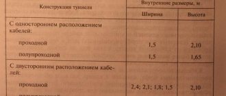
Wire insulation is an important process that can be encountered not only at home, but also at work. The solution to this problem must be effective and of high quality. Or you may face a short circuit, jeopardizing not only your home, but also the health of you and your loved ones. Therefore, in order to avoid mistakes when performing insulating coating of current-carrying conductors, in this article we will consider several basic methods and types that are easily applicable to every person.
Insulating joints of electrical wires
Wire insulation and materials for it.
Rubber-based insulating materials used in cable production can be of either natural or synthetic origin. Sufficiently high flexibility is an important advantage of rubber insulation of wires and wiring, which allows installation of networks in any conditions. However, this type of insulation also has a drawback: the rubber insulating braid over time undergoes a change in the chemical properties of the material and loses its protective properties, which negatively affects the reliability of the insulating layer.
The insulation of wires made of low- or high-density polyethylene is characterized by a high degree of resistance to chemical or other aggressive environments. Conventional types of polyethylene insulation are unstable when heated, but vulcanized polyethylene is not afraid of temperature changes, so it is recommended to use it in conditions of elevated temperatures.
PVC-based wire insulation materials are polymer derivatives that have all their advantages and disadvantages. PVC insulation is cheaper for manufacturers than any other types of insulating materials, but the braiding of the wire or wire somewhat loses its protective properties and the chemical resistance of the material decreases when plasticizers are added. At the same time, wire insulation based on PVC materials is highly elastic, and by selecting the right additives, you can give it additional properties such as heat resistance and maintaining elasticity under low-temperature conditions.
With the abundance of modern materials, paper-based wire insulation today is used quite limitedly. For this type of wiring, the permissible voltage is no more than 35 kV. If paper insulation is used in the production of power wires, then the paper base must be impregnated with a special composition, which includes oil, rosin and wax. As a result of these activities, the paper acquires characteristics unusual for it. But the instability of paper to any external influences is a huge disadvantage of this type of insulation.
Situations requiring additional insulation
Insulating wires is usually necessary after making connections between individual lines to ensure safety from electric shock. In this case, the following situations occur when insulating material is needed:
- If a separate section of the cable line’s protective layer is damaged. This will allow you not to replace the entire conductor, but only to insulate the damaged protection layer.
- When located in close proximity to the electrical equipment housing, unprotected current-carrying conductors.
- For marking wires of the same color.
- For bundling separately lying thin wires.
Insulating joints of electrical wires
Types of heat-resistant wires
Heat resistant wire
Since the wires can be used in different conditions, the requirements for them will also differ. Each model will have its own resistance to adverse factors and operating conditions. These features must be taken into account when choosing the optimal conductor. Popular types of conductors for connection are RKGM, PRK, PRKS, PAL and others.
The listed models tolerate high temperatures well. At zero and negative temperatures, other conductors are used.
RKGM
The most used heat-resistant wire is RKGM. It has the following characteristics:
- voltage up to 660 V;
- cut area from 0.75 sq.mm. up to 120 sq. mm;
- temperature range from -60° to +180°C;
- 1 core;
- the minimum operating time if the requirements are met is 8 years;
- inert to changes in atmospheric pressure;
- resistance to mold formation;
- withstands vibration, mechanical stress, solar radiation, radiation.
MVV
Heat-resistant wire MVV
Heat-resistant MVV wire can withstand temperatures up to +500°C for long periods of time. It is resistant to fire, but performs less well at low temperatures.
Characteristics:
- works in electrical networks up to 500 W;
- cross section from 1 sq.mm. up to 25 sq. mm;
- single-core;
- operating temperatures from -60° to +500° C.
Application - electrical appliances and powerful equipment, hot shops, baths, industrial premises with the presence of chemical elements. Also used in heating components.
PRKA
PRKA
Heat-resistant wire with a copper core and silicone rubber sheath is used in rooms with high humidity. These include bathrooms, saunas, steam rooms, swimming pools, production workshops and other types of objects with an unstable microclimate.
Main parameters:
- rated voltage up to 660 V;
- cross section from 0.5 sq. mm. up to 2.5 sq. mm;
- temperature range from -60° to +180°С;
- single-core
Does not support combustion. No halogens in the braid.
PRKS
PRKS
High-temperature stranded wire PRKS stands for copper connecting conductor with silicone insulation.
Options:
- operates up to 380 V;
- cross section from 0.75 sq. mm. up to 10 sq. mm;
- temperatures from -60° to +180°С. Short-term use up to 250°C is possible;
- number of cores from 2 to 5;
- used in brewhouses, bathhouses and other facilities with extreme conditions.
This model is used at high temperatures with jumps up to +250°C. Does not emit toxic substances. Stranded wire can be used to transmit electricity up to 30 kW.
PVKV
PVKV
Marking of heat-resistant wire:
- P – wire;
- B – application for output ends of electric machines;
- KV – two-layer insulation made of silicone rubber.
Options:
- voltage up to 400 V;
- cross-sectional area from 0.5 sq. mm. up to 95 sq. mm;
- operating temperature up to 200°C;
- number of cores – one or more;
- used in single installations in rooms, shafts, tunnels;
- does not melt, does not burn;
- Resistant to atmospheric pressure surges.
PMTK
PMTK
Deciphering the wire shows that it is heat-resistant and has protection made of silicone material. Operates in electrical networks up to 660 V and temperatures up to +200 degrees Celsius. On sale you can find single-core and stranded conductors with a cross-section of up to 4 sq. mm.
Actively used in places with an increased risk of fire. Can be installed in baths, saunas, hot shops, and in production. Withstands temperatures up to 180°C.
Application of rubber insulation
In industrial applications, rubber sheathing is often used to insulate cables. Its positive qualities include:
- Moisture resistance.
- Elasticity.
- High resistance.
- High temperature resistance.
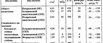
Rubber insulation is made on the basis of natural and synthetic materials. High-quality synthetic braid has better performance - it ages longer, withstands the effects of aggressive chemicals and negative temperatures. The rubber bends easily, so the wires can be laid in any conditions. But over time, the rubber insulation ages, cracks and begins to conduct current. In high temperature environments, it is recommended to use vulcanized rubber for insulation. Rubber insulated cables are most often used where cable flexibility is required. These are power cables of cranes, descents to control panels of crane beams. Connecting welding transformers, both from the power side and from the low voltage side to the electrode “holder” and the neutral wire.
Optimal thickness - insulation
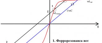
| Graph of the dependence of the reduced S, capital K and operating E costs on the insulation thickness. |
The optimal insulation thickness depends on the properties of the insulating material: the lower the thermal conductivity coefficient, the thinner the insulation thickness, and vice versa.
The economically optimal insulation thickness, corresponding to the lowest operating costs, is determined by comparing the costs of depreciation, repair and maintenance of insulation with the cost of heat lost to the environment.
Determining the optimal insulation thickness is a technical and economic problem and, in general, very difficult, since in addition to the insulation thickness, several more parameters have to be optimized: temperatures at the outlet and inlet of thermal stations, the number of thermal and pumping stations, etc. However, in practice, taking into account design experience and operation of hot oil pipelines, the optimization problem can be simplified.
When calculating the optimal insulation thickness taking into account operational losses from drying out products with conventional battery cooling of chambers, its value turns out to be so large that it is not possible to practically use such values. In other words, the fight against shrinkage of products, especially in the southern regions of the Soviet Union, cannot follow the path of simply extinguishing external heat inflows by increasing the thickness of the insulation.
Thus, the optimal insulation thickness depends on the temperature difference between the inside of the device and the environment, the number of hours of loss per year, the thermal conductivity of the insulation and the heat transfer coefficient. Determining only the optimal insulation thickness without taking into account the quantitative change in the Sp / ( 6) function in the minimum zone is insufficient to make a final decision. It is necessary to consider not the optimal point of 60pt, but the optimal zone within which a certain insulation thickness can be accepted, taking into account its normalized thickness, the availability of certain materials, technical and economic indicators of thermostatic devices, energy costs and other factors.
In order to find the optimal insulation thickness corresponding to the minimum total costs, we determine these costs using the last equation for insulation layers of different thicknesses.
| Nomogram diagram for determining the maximum permissible value. |
Direct determination of Yain and the optimal insulation thickness by differentiation is very difficult here, and therefore the calculation is carried out using a computer.
In these cases, additional tests and calculations must be carried out to determine the optimal insulation thickness. For example, for corded cables, INSULATION crush tests are carried out.
In most Western countries, when energy prices rise, the optimal insulation thickness is recalculated and, if necessary, increased. Such work is also necessary in our conditions.
Based on the data below, we will determine, firstly, the optimal insulation thickness and, secondly, which of the options for insulating a liquefied gas storage tank will be cost-effective.
Next, having determined the cost of depreciation of refrigeration and energy equipment, as well as the insulation itself, you can find the optimal thickness of the insulation of the external contour of the refrigerator, which should meet the minimum annual costs associated with external heat inflows.
| Final distribution matrix. |
A number of economic problems in the field of design and operation of equipment used in gas separation can be successfully solved by conventional methods of classical analysis (selection of the optimal insulation thickness, assessment of the comparative economic efficiency of various types of heat exchangers, selection of the optimal size of enterprises, etc.
Terminal Applications
Terminals in a dielectric shell are used as insulation. Terminals are sold in the form of caps or blocks that clamp the wires. If you want to insulate the wires in the junction box, then the choice of terminals is one of the connection options.
But a lot depends on the load. At high loads, it is better to use soldering for connections, and put an insulating tube on top. Tightening aluminum wire with screw terminals is not recommended because aluminum will begin to leak under constant pressure. As a result, the connection weakens, resistance increases and a short circuit occurs. If you decide to connect aluminum wires with terminals with screws, then you need to do an inspection at least once a year. Connecting copper and aluminum wires by twisting is unacceptable. When current passes between metals, an electric potential arises, the wires heat up, which can cause a short circuit or, worse, a fire. However, in one case, twisting can be done - if the copper wire is coated with tin-lead solder (tinned). But more often, terminal blocks or the threaded method (screw, nut and washer) are used to connect both aluminum and copper.
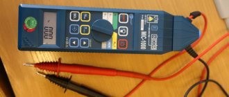
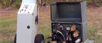
Algorithm for measuring the insulation resistance of high-voltage power cables.
To understand and simplify the process of performing work on measuring insulation resistance in high-voltage power cables, we recommend the procedure for taking measurements.
1. Check the absence of voltage on the cable using a high voltage indicator
2. We install a test ground using special clamps on the cable conductors on the side where we will carry out the measurement.
3. On the other side of the cable we leave free conductors, while we separate them at a sufficient distance from each other.
4. We place warning information posters. It is advisable to place a person on the other side to monitor safety while measuring with a megohmmeter.
5. We measure each core for 1 minute with a 2500 (V) megohmmeter to obtain indicators of the insulation resistance of the power cable.
For example, we measure the insulation resistance on the conductor of phase “C”. At the same time, we place the grounding on the conductors of phases “B” and “A”. We connect one end of the megohmmeter to grounding, or, more simply, to “ground”. The second end is to the core of phase “C”.
Visually it looks like this:
6. We record measurement data in the process of work in a notebook.
REPORT on insulated power cables
Your attention will be presented with information on power cables with cross-linked polyethylene insulation (XLPE) - extruded insulation for voltages of 1-10 kV.
REPORT on power cables with cross-linked polyethylene insulation (with extruded insulation) for voltage 1-10 kV
Your attention will be presented with information on power cables with cross-linked polyethylene insulation (XLPE) - extruded insulation for voltages of 1-10 kV.
The information has been prepared for the purpose of conducting an expert assessment of new products.
During the expert assessment, materials from manufacturers of power cables with XLPE insulation (Pirelli, Nexans, ABB-Moskabel, Irkutskkabel), as well as GOST 16442-80 “Power cables with plastic insulation”, TU 16.K71.277-98 “Power cables” were used with insulation made of silanol cross-linked polyethylene for a voltage of 1 kV,” and publications IEC 60502-2-1997 “Power cables with extruded insulation and fittings for them for rated voltages from 1 to 30 kV.”
The distribution cable networks of the Northwestern Federal District and Moscow are the longest in comparison with other power systems in Russia and one of the oldest in the history of formation and development.
These circumstances, on the one hand, largely determine the problems of cable operation associated with the long service life and length of networks, and on the other hand, they allowed the specialists of the power systems of St. Petersburg and Moscow to accumulate experience and traditions, which are then used in regional power systems.
Currently, the cable network of Moscow and St. Petersburg has a total length of more than 100 thousand km
Medium voltage cable network 6-10 kV, this is more than 90% - cables with impregnated paper insulation.
According to Cable Network JSC, the specific damage rate of cable lines for voltages of 6-10 kV for cables with impregnated paper insulation (IIP) in a lead sheath (laying length more than 50% of the total number of cables laid) ranges from 4.3 to 5.0 cases per 100 km per year (data for 1999-2000, report by the director of the Moscow Electric Grid Company A.S. Svistunov).
Introduction to the CS in 1998 100% control of the cable before installation gave a very good effect and turned out to be an effective measure that helps improve product quality.
The technical policy of energy systems to improve the performance of cable lines, the main one of which is the reliability of cable lines, is aimed at using cables with XLPE insulation, both in the construction of new lines and in the reconstruction of existing ones.
Consider the advantageous parameters of cables with XLPE insulation stated by product manufacturers:
This product group has a number of advantageous characteristics compared to cables with BPI. It should be noted the main advantages of cables with XLPE insulation in a single-core version are:
- large construction lengths;
- extended range of nominal sections, up to 500 mm2;
- lower weight, diameter and bending radius (we are talking about laying one phase).
1. Designs of power cables with XLPE insulation
Single phase design:
- Conductive stranded compacted conductor made of aluminum or copper;
- XLPE insulation;
- Screen over core and insulation (0.3 mm thick PE);
- Screen made of copper wires;
- Water blocking elements;
- PVC or PE sheath.
The main advantage of cables with XLPE insulation is their high throughput due to an increase in the permissible core temperature. The permissible load currents, depending on the installation conditions, are 15-30% greater than that of a cable with PPI (Nexans catalog, page 3)
When calculating current loads, the choice of the long-term permissible heating temperature of the cores and the maximum short-circuit temperature is determined by the type of insulating materials. The temperatures shown in Table 1 are based on the physical properties of the insulating materials.
2. Maximum TPZ temperatures for cables for voltage 10 kV with different types of insulation
| Characteristic | Cables with XLPE insulation | Cables with BPI |
| Long-term permissible core heating temperature, °C | 90 | 70 |
| Maximum temperature during short circuit, °C | 250 | 200 |
Table 1
Long-term permissible current loads of cables, calculated in accordance with the requirements of IEC 60287 - 1994 “Calculation of rated current loads of cables under steady-state conditions.” A constant current during continuous operation (100% load factor) sufficient to asymptotically produce a maximum core temperature under constant ambient conditions.
However, experience in operating cables with XLPE insulation in European power systems has shown that when determining the long-term permissible current, in addition to the insulation properties of the material, it is necessary to take into account the installation conditions and the initial data for calculating the permissible load current.
Thus, the leading Western company producing cables with XLPE insulation f. Pirelli in its information materials (Pirelli catalogue, p.) stipulates the following condition:
3. “In connection with laying cables with extruded insulation in the ground, it is necessary to take into account the fact that a long-term core temperature of +90°C can dry out the nearby soil and thus cause cable overload. Based on this, we recommend limiting the long-term permissible temperature of cable cores with XLPE insulation laid in the ground to +65°C.”
The international standard IEC 60502-2 (IEC 502) “Extruded insulated power cables and their accessories for rated voltages from 1 kV to 30 kV”, in its 1997 edition, reiterates this recommendation.
4. Consider a table comparing permissible current loads for cables with BPI and XLPE insulation for a voltage of 10 kV when laid in the ground in a triangle for single-phase cables.
| Section of TPG/screen, mm2 | Permissible current loads, A | |||||
| Three-phase cable | Single phase cable | |||||
| Cables with BPI (GOST 18410-73) | f. "Nexans" | F. "Pirelli" | ABB-Moskabel (TU 16.K71.300-2000) | Irkutskkabel (TU 16.K71.335-2004) | ||
| 70°C | 90°С | 90°С | 65°С | 90°С | 90°С | |
| 120 / 16 | 218 | 275 | *320 | *270 | 280 | 288 |
| 185 / 25 | 275 | 346 | *405 | *345 | 360 | 364 |
| 240 / 25 | 314 | 401 | — | — | 415 | 422 |
| 300 / 25 | — | 451 | *525 | *445 | 475 | 476 |
| *Shared screen circuit is open | ||||||
table 2
The presented values of permissible current loads for one cross-section of cables with XLPE insulation have a significant range of values:
- for a cross section of 120 mm2 - from 270 A to 320 A, which is 16.4%;
- for a cross section of 185 mm2 - from 345 A to 405 A, which is 17.0%;
- for a cross section of 300 mm2 - from 445 A to 525 A, which is 16.4%.
This circumstance is explained by the fact that national standards, which differ from each other, were taken as the initial data for calculating permissible current loads.
5. Initial data for calculating permissible current loads when laying in the ground
| Options | Company name | |||
| Cables with XLPE insulation | cables with BPI | |||
| f."Nexans" | f."Pirelli" | Russian manufacturers | ||
| Soil temperature, °C | +20 | +15 | +15 | +15 |
| Soil thermal resistivity coefficient, K*m/W | 1,0 | 1,0 | 1,2 | 1,2 |
| Laying depth, m | 0,7 | 0,7 | 0,7 | 0,7 |
| Long-term permissible temperature of TPG, °C | 90 | 65 / 90 | 90 | 70 |
| Current load factor | 0,7 | 1,0 | 1,0 | 1,0 |
Table 3
Please note that when calculating the current load of a single-phase cable when laid in the ground, it is necessary to take into account a number of correction factors.
f. "Pirelli" and f. Nexans provide information for making these adjustments in their catalogs (Pirelli catalogue, page 9).
6.
When laying in the ground, it is also necessary to take into account the method of connecting the power cable shields. If you select a screen connection scheme:
- The circuit is open - the common cable shields are connected and grounded at only one end of the route.
- The circuit is closed - the common cable shields are connected at both ends of the route and are grounded in any case at one of the ends of the route.
Adjustment of the permissible current load for this factor is carried out with a significant reduction from 4 to 17.3% depending on the cross-section of the conductor.
Using the example of a specific installation of a cable with XLPE insulation for a voltage of 10 kV produced by f. “Pirelli” (analogue of APvP(g) brand cable) let’s see how the system of correction factors for all these factors affects the permissible current load. The cable is laid in the ground with an open circuit of the common screen
Layout diagram (Nexans instructions p. 39):
7. Laying cables with XLPE insulation for a voltage of 10 kV in a trench, the distance between cable lines when laid in parallel in the ground
Thus, the values of correction factors for laying the cable in the presented diagram can be seen in the table
- The influence of several laid parallel groups K1=0.87;
- Laying depth K2=1.0;
- Coefficient of specific thermal resistance of soil K3=0.92;
- Ground temperature K4=1.0;
- Influence of protective coatings K5=1.0.
The result of adjusting the current load is presented on slide No. 8.
8. Permissible current loads of cables with XLPE insulation, taking into account correction factors when laying in the ground
| / screen, mm2 | Permissible current loads, A | ||||
| Three-phase cable | Single phase cable | ||||
| Cables with BPI (GOST 18410-73) | F. "Pirelli" | ||||
| Rated current load | Current load taking into account correction factors | ||||
| 70°C | 90°С | 65°С | 90°С | 65°С | |
| 120 / 16 | 218 | 320 | 270 | 256 | 216 |
| 185 / 25 | 275 | 405 | 345 | 324 | 276 |
| 240 / 25 | 314 | — | — | — | — |
| 300 / 25 | — | 525 | 445 | 420 | 356 |
Table 4
Taking into account correction factors, the permissible current load is expected to be reduced by 20%.
Please note that f. “Pirelli” in its product catalogs, when assigning current loads for cables with XLPE insulation for a voltage of 1 kV for laying in the ground, retains the same recommendations as for laying cables with XLPE insulation for a voltage of 10 kV. At the same time f. Pirelli recommends reducing the long-term permissible temperatures of conductors when laying in air to 70°C (Pirelli catalog, page 16).
With this installation method, the requirement for greater throughput of cables with XLPE insulation is not met.
Laying in air is a large area of application for this product.
9. Consider a table comparing permissible current loads for cables with BPI and XLPE insulation for a voltage of 10 kV when laid in air in a triangle for single-phase cables
| Permissible current loads, A | |||||
| Three-phase cable | Single phase cable | ||||
| Cables with BPI (GOST 18410-73) | F. "Pirelli" | ABB-Moskabel (TU 16.K71.300-2000) | f. "Nexans" | Irkutskkabel (TU 16.K71.335-2004) | |
| 25°С | 25°С | 25°С | 30°С | 25°С | |
| 120 / 16 | 234 | *325 | 330 | 321 | |
| 185 / 25 | 298 | *425 | 425 | 418 | |
| 240 / 25 | 347 | — | 505 | 494 | |
| 300 / 25 | — | *565 | 580 | 568 | |
| *Shared screen circuit is closed | |||||
Table 5
When laying in air, current loads should also be adjusted according to the following factors:
- Ambient temperature;
- Mutual influence of cables during group installations (Pirelli catalogue, page 11):
- by the number of parallel systems;
- by the number of systems located on top of each other.
10.
11. Recommends f. "Pirelli" installation scheme in the air, which does not require a reduction in permissible current loads
The permissible current loads indicated in the table are valid provided that the ambient temperature does not increase as a result of the influence of heat losses occurring in the cable.
12. For other ambient temperatures, it is necessary to apply the correction factors indicated in the table.
| Design ambient temperature | Correction factor at ambient temperature | ||||||||||
| -5°C | 0°C | 5°C | 10°C | 15°C | 20°C | 25°С | 30°С | 35°С | 40°C | 45°С | |
| 25°С | 1,21 | 1,18 | 1,14 | 1,11 | 1,07 | 1,04 | 1,0 | 0,96 | 0,92 | 0,88 | 0,83 |
Table 6
Thus, based on the materials presented above, it is clear that cables with XLPE insulation for a voltage of 10 kV have a high throughput only when they are operated in air with certain installation schemes.
When laying this group of products in the air, given the high degree of flammability of the insulation, it is necessary to carry out special fire protection measures to ensure fire safety, which requires additional costs.
Conclusions:
From the information presented on cables with XLPE insulation it follows that the selection of permissible current loads for this product group requires a careful approach. There is an obvious need to develop Guidelines for the design of cable lines and a chapter of PUE dedicated to these products for designers and operating organizations.
Installation and diagnostics of cables with XLPE insulation
As is known, the reliability of a cable line depends not least on the quality of laying and installation of cables, as well as the ability to diagnose the condition of cables during their acceptance into service and during subsequent operation. Due to the lack of regulatory documents for the laying and installation of cables with XLPE insulation, when considering these issues we will use the “Instructions for the use of power cables with cross-linked polyethylene insulation for voltage 6-35 kV”, issued by f. "NEXANS" (Instruction NEX/6-35.04). The instructions establish the following basic requirements for laying cables in the ground: (return to slide No. 7).
It is not allowed to lay cables with XLPE insulation under the following conditions:
- in places contaminated with petroleum oils with a high content of aromatic hydrocarbons (including cable and transformer oils) or other substances;
- if the bulk soil contains slag or construction waste;
- in areas located at intersections with heating network lines or in close proximity to them.
If it is impossible to bypass these places, the cable must be laid in clean neutral soil in asbestos-cement pipes coated outside and inside with a bitumen composition. When backfilling the cable with neutral soil, the trench should be further expanded on both sides by 0.5-0.6 m and deepened by 0.3-0.4 m.
Backfilling the bottom of the cable route trench and backfilling the cable must be done with a sand-gravel mixture (sand with a grain size of no more than 2 mm and gravel with a particle size of 5 to 15 mm in a ratio of 1:1).
In a trench, cables with XLPE insulation are laid in a triangle or in one plane. When connecting cables in a triangle, after laying the cables, they must be fastened together into a triangle after 1 - 1.5 m with tapes, clamps or staples made of non-magnetic material. Simultaneous laying of three cables along the route in the same plane is prohibited.
To protect the cable from mechanical damage, reinforced concrete slabs or bricks should be used. (Warning tape is not allowed).
Cable laying should only be carried out along rollers. The distance between the rollers in straight sections should be no more than 4 m. When pulling, the cable should not touch the bedding.
From the above it is clear that the additional requirements imposed by the cable manufacturer for its installation require relatively high qualifications of the personnel involved in its installation, as well as the availability and quality of auxiliary materials and tools.
Installation of cables with XLPE insulation also has its own characteristics, but can be carried out quite quickly if qualified personnel and specialized tools are available. It should be emphasized that cable couplings from different manufacturers have their own characteristics in installation, however, any manufacturer of couplings offers training services for the installation of their couplings.
After the cable is installed, it must pass acceptance tests.
Unfortunately, different sources indicate different standard test voltage values for testing cables after installation, which is reflected in the table.
13.
| p/p | Standard value for cables with a rated voltage of 10 kV | |||||
| Test voltage | ABB-Moskabel | Irkutskcable | f. "Nexans" | IEC 60502-2 | PUE | |
| 1 | Alternating voltage frequency 0.1 – 400 Hz | 30 kV for 15 min | 30 kV for 15 min | 25 kV for 15 min | — | — |
| 2 | AC voltage 50 Hz | 10 kV for 24 hours. | 10 kV for 24 hours. | 10 kV for 24 hours. | 10 kV for 24 hours | — |
| 3 | Constant pressure | 60 kV for 15 min | 40 kV for 15 min | 60 kV for 15 min | 24 kV for 15 min | 60 kV for 10 min |
Table 7
Quite a lot of attention is paid to the issues of testing and diagnosing the condition of cables with XLPE insulation abroad. This is due, first of all, to the design features of the cable itself and the insulation material. In Russia, tests with increased voltage and reduced frequency of 0.1 Hz are accepted.
For cables with extruded insulation, test standards are regulated by ND:
- GOST 55025-2012 Power cables with plastic insulation
- TU16-K71-335-2004 Power cables with cross-linked polyethylene insulation for voltage 10,20,35 kV
Abroad, standards are presented by manufacturers of testing facilities, for example SEBA
Let's look at a typical XLPE insulation defect.
14. The main reason for the increase in the level of partial discharges when operating cables with XLPE insulation is the increase in trees in the insulation. A typical picture of trees in the insulation of a cable that was in operation is shown in the figure.
Can a test with increased voltage applied between the core and the screen reveal this defect? The question is rhetorical, since the indicated defect does not violate the integrity of the insulation.
Moreover, extensive research has been carried out abroad, proving that high-voltage tests not only do not allow an adequate conclusion to be made about the condition of the cable, but also significantly weaken the insulation. These issues are discussed in more detail in a number of publications (including in the magazine “Electricity Today” “A Non-Destructive Method For Testing Underground Cables Up To 25 kV” by Claude Kane, Westinghouse Electric Corporation). In this article, based on studies conducted, it is reported that tests with increased direct voltage reduce the service life of cables and increase the growth of water trees.
As alternative methods for diagnosing the condition of cables with XLPE insulation, foreign experts offer various non-destructive testing methods:
- partial discharge measurement;
- tan delta measurement at a frequency of 0.1 Hz;
Abroad, where cables with XLPE insulation have been in use since the 70s of the last century, there is still no consensus on the optimal diagnostic method. Results of diagnostics of cables with XLPE insulation carried out by the Danish company DEFU as part of a joint Scandinavian project to evaluate various diagnostic methods for cables with XLPE insulation
The figure shows the results of studies of cables with XLPE insulation at 10 kV
As can be seen from Figure 15, 61 cables were tested. All cables were put into operation between 1981 and 1996. Based on the test results, the cables were divided into 4 categories:
- good cables;
- cables showing signs of aging;
- highly aging cables;
- cables with leakage current.
The group of cables with a service life of 5 to 10 years included cables from all four groups.
It was also found that of the ten severely aged cables, only one had an intact outer sheath. This indicates a relationship between damage to the outer sheath and aging of the insulation, i.e. reduction of cable service life.
From all of the above, several main conclusions can be drawn:
- The requirements for laying cables with XLPE insulation are much stricter than for laying cables with BPI.
- There are differences in the value of the test voltage recommended by various manufacturers, IEC and established in the PUE.
- Experts do not yet have a consensus on the choice of the optimal method for diagnosing the condition of cables with XLPE insulation.
- The lack of a national standard may result in cables of inadequate quality being put into service.
The latter conclusion is partly confirmed by the fact that certification of cables with XLPE insulation in the Russian Federation is carried out not for compliance with the national standard, but for compliance with the manufacturer’s documents and is carried out in a voluntary certification system according to the characteristics declared by the manufacturer.
In conclusion, I would like to note that the purpose of this publication was to draw attention to certain features of promising products, as well as the need to work on creating national regulatory documentation for cables with XLPE insulation. However, the choice of cable design to ensure the reliability of power systems rests with energy company specialists.
Test standards:
- Test standards No. 1
- Test standards No. 2
Properties of heat-resistant cables
Structure of heat-resistant wire
Heat-resistant products have improved protection compared to classic conductors. This has led to the fact that the service life of such electrical installation devices increases significantly. The cable can be covered with such types of protection that will allow it to be installed even in places with a high risk of bacterial or chemical destruction. The protective layer is resistant to the formation of fungus, mold and other cultures on the cable surface.
The cable withstands high temperatures better. When cold, the protective coating can crack, making the conductor unsuitable for further use.
When buying a device, you need to familiarize yourself with its characteristics in advance so as not to make a mistake in the operating conditions of a particular model.
The process of using electrical tape to form a protective coating
The procedure for applying the protective layer of electrical tape depends on the type of surface being treated. If you plan to insulate the junction of two conductive wires, it is recommended to adhere to the following sequence:
- Twist and solder.
- The electrical tape is applied at an angle, catching a small portion of the main insulation towards the end of the twist.
- At the next stage, you will need to carefully bend the twist so that it is parallel to the main protective coating.
- Another layer of electrical tape is applied, but this time towards the factory insulation.
- The applied electrical tape is pressed with hand force and the excess material is cut off.
To restore the protective coating on a solid conductor, it is recommended to perform the following steps:
- The tape is laid at an angle, capturing part of the main insulation towards another undamaged area.
- Next, the insulating material is applied in the opposite direction.
- The electrical tape is carefully pressed with your hands, followed by removal of excess material.
Types of wire insulation.
Based on the design features of the wire and the mains voltage at which it will be operated, the type of wire insulation is selected:
- for non-sheathed cable products, the indicators of which have no more than 700 Volts of direct voltage and no more than 220 Volts of rated alternating current for single-phase networks (for three-phase networks 380 Volts);
— for sheathed cable products with direct voltage not higher than 700 Volts and rated alternating current not more than 220 Volts for single-phase networks (for three-phase networks 380 Volts);
- for sheathed and non-sheathed wires with direct current ratings of no more than 700 - 1000 Volts and alternating current from 220 to 400 Volts (for single-phase networks at 220 Volts and three-phase networks at 380 Volts);
- for wires with a constant voltage of up to 3600 Volts and an alternating current indicator of 400 to 1800 Volts;
- for wires that are operated under constant voltage conditions of 1000 - 6000 Volts with alternating current values of 400 - 1800 Volts.
Wiring insulation using terminals
To create the shell, terminals are used - these are small clamps that are widely used, including for connecting wiring. Terminals can and should be used to insulate wiring in a junction box.
It is better not to use terminals together with aluminum wiring with screws, because... Due to strong pressure on the wire, this metal will begin to leak. A short may eventually occur due to the weakening of the connection and increasing resistance. If you do insulate using terminal blocks, do not forget to inspect the electrical wiring connection at least once a year.
It is strictly prohibited to connect wiring made of materials such as copper and aluminum using twists. Due to the incompatibility of these metals, at least a short circuit will occur, or at most a fire. This will put your life at risk.
So today you have learned everything you need to know about insulating electrical wiring. We examined the materials and methods for creating a wire sheath. I hope that after reading this article, you have decided which wire insulation is best for you.
Heat shrink tubing
The material from which these tubes are made is polymer. I note that it is best to use this type of shell on low-voltage equipment, when the voltage is not higher than 1 kV.
In order to use this method of creating a casing for electrical wiring, you need to follow some steps:
- First you need to prepare a piece of heat-shrinkable tubing. To do this, measure the exposed section of the electrical wire, after turning off the electricity. We cut off a piece of tube, it is better if it is a little larger than needed. About 2-3 centimeters.
- Next, take a piece of tube and put it on the end of one of the wires.
- After completing the second step, you need to twist the wiring.
- The last step is to transfer the heat-shrinkable tube to the junction of the wiring and use a hair dryer to secure the result.
After these steps, the heat shrink tube will be pressed tightly against the wiring. If you don't have a hair dryer, a lighter will do. It should be carefully kept at a small distance from the junction of the wires.
There are different tubes. It all depends on the desired temperature that the tube must withstand, as well as on the voltage. To find out the characteristics of the tube, you need to look at the markings that manufacturers put on at the factory for the manufacture of these products.
There are tubes of different diameters, colors, and also for certain cable sections. This plus allows you to select the most suitable heat shrink tube.
Color coding of wires and cables
Color marking of cables and wires is also used, in accordance with GOST 28763. It is carried out along the entire length of the wiring or at the ends. So, according to GOST standards, grounding is always a yellow-green wire, the neutral and middle conductor are marked in blue. And for the phase they use white, red and other permitted shades. Allowed colors and combinations are shown in the table.
It is prohibited to use yellow and green separately for marking. The yellow-green combination is used only to indicate grounding.
Wire insulation: precautions
Before you decide to insulate electrical wires, you must clearly understand that they must be disconnected from the network. It is best to turn off the voltage using a circuit breaker. Next, you must make sure that there is no voltage at all.
Pay attention to the materials you are going to use, this is very important. If it can catch fire, it will lead to an accident. Read on for my review of insulation materials
Let me note right away that it is impossible to insulate the wire underground.
Read on for my review of insulation materials. Let me note right away that it is impossible to insulate the wire underground.
Cables for information transmission
Antenna cables
RG-6
Intended for transmitting signals from electronic equipment. This cable is coaxial, copper core, which has a cross-section of 1 mm. Polyethylene insulation.
RG-6 cable
Cable RK 75
It is considered the best for transmitting video signals to various antennas and video cameras. It can be used to transmit multiple sources at once.
Cable RK 75
Sectional view of cable RK 75
RG
It has many varieties. The main feature is that it is resistant to temperature and various shock loads.
Area of use
Using heat-resistant wire in sauna wiring
Heat-resistant stranded wire is intended for use in such operating conditions when a regular conductor cannot be installed. Heat-resistant wire is selected depending on the intensity of exposure to external factors.
The main areas of application of heat-resistant wires are:
- Laying electrical wiring indoors, especially in buildings with a high risk of fire hazard.
- Laying cables outdoors. Here, the conductor will be affected by environmental factors - weather conditions, precipitation, direct sunlight.
- Winding of electrical installations and AC machines.
- Installation of wires for high temperatures in environments with chemicals or bactericidal threats, as well as the risk of mold growth.
- Installation in facilities where sudden temperature changes are observed.
Thermal wire with braid or seal can be used to connect components of electric stoves and electric furnaces. You can also install an additional tube for the wire to protect it from damage or contamination.
Types of insulating materials and their scope of application
Depending on the planned operating conditions and the type of connection of the conductors, various types of insulation can be used. Let's look at the most popular options.
Insulation tape
Insulating tape is the most affordable and popular way to protect current-carrying conductors. The scope of its application directly depends on the material of manufacture.
Polyvinyl chloride
The tape is available in widths from 10 to 20 mm. Adhesion to the protected surface is ensured by a special adhesive compound applied to the inner surface of the tape. Manufacturers produce products in various colors. The positive basic properties of PVC electrical tape include:
- strength;
- adhesion to many types of surfaces;
- ability to withstand significant temperatures - up to 120 degrees Celsius;
- withstand increased voltage;
- elasticity;
- high level of fire safety;
- resistance to external factors: moisture, alkali, acid.
Insulating the wire with PVC tape
Among the disadvantages, the loss of useful properties when used in subzero temperatures stands out.
PVC insulating tape is widely used in the electrical industry, as well as in everyday life. Electrical tape for wiring with voltage levels up to 1000 Volts can last a long period of time.
Note! If necessary, it is allowed to insulate high-voltage cables. According to the recommended performance indicators, one layer is capable of providing safety at a voltage level of 660 V.
In addition to these cases, the material is actively used for the repair of pipelines, household appliances and packaging of goods.
Types of PVC insulating tape
Cotton
The basis of the product is cotton material with the addition of rubber, on the inside of which an adhesive solution is also applied. Some manufacturers use fiberglass as the base material. Tapes are produced with a width from 15 to 50 mm. Positive characteristics include:
- high strength;
- increased wear resistance;
- thermal stability;
- low cost.
The negative aspects of cotton insulating material include:
- risk of ignition due to overheating;
- liquid absorption.
Fabric insulating tape TESA
The main area of application of CB electrical tape is the protection of electrical wiring with voltage levels up to 1000 Volts. It is recommended to use it exclusively in closed and dry rooms. In electrical installations of higher voltage it is used as an additional means to increase the frost resistance at the junction of conductors.
Heat shrink tubing
Heat-shrinkable tubes are made from polymers (PVDF, PET, silicone and others). They are used mainly on low-voltage equipment, when the DC voltage does not exceed 1 kV.
If you want to use heat shrink for wires, then you need to perform a number of steps.
- Cut off a piece of heat-shrink tubing that completely covers the exposed section of the wire (connection), with a margin of about 2 cm.
- Then you need to put a tube on one of the ends of the wires to be connected.
- Twist the conductors.
- After this, the tube is moved to twist and heated with a construction hairdryer.
As a result of heat shrinking, the insulation is pressed tightly against the wires. If you don’t have a hairdryer, you can use a lighter, carefully holding it at a short distance. This is done when insulating twisted wires connected in series. If the connection of wires is parallel (the so-called bundle of wires), then first twist it and then put on the tube. In most cases, heat shrink tubing is easier to use than electrical tape. The tube can be quickly put on; it fits the wire connection more tightly and does not unwind. But it is more difficult to remove it if necessary. You just have to peel it off or cut it off. Manufacturers put markings on the tubes that show what temperature it can withstand and what voltage it is suitable for. Tubes are produced in different diameters and colors, so for different brands and cable sections it is always possible to select the appropriate insulation and color marking. How to properly insulate wires using heat shrink tube, watch the video:
Thermal shrink tubes
Heat shrinking is a modern and more reliable method of insulating conductors. Heat-shrinkable tubes are available in various diameters and lengths (up to one meter). They are not collapsible and not universal, so they must be selected for a specific conductor diameter. During the installation process, the original cross-section narrows almost in half. This ensures a secure fit to the protected surface.
Special polymers are used to make thermotubes: polyethylene, silicone, and so on. To improve the adhesion performance with current-carrying conductors, hot-melt adhesive is additionally used in the internal cavity of the tube. At the same time, they can be easily used in various climatic conditions, withstanding exposure to aggressive environments.
Heat shrink tubing for wire insulation
The operating temperature range of standard heat shrinks is from - 50 to + 125⁰С, but products are produced that can withstand up to 260⁰С. Thanks to the use of special polymers, manufacturers produce the following types of heat shrinks:
- heat resistant;
- with increased strength;
- semiconductor;
- corrugated;
- fluorescent.
The scope of application of thermotubes is very wide. With their help, cable insulation with voltage values up to 110 kV can be restored.
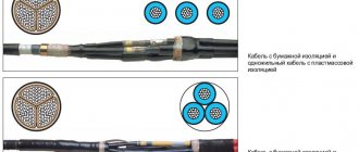
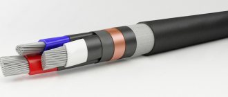
Cable insulation and materials for it.
Rubber-based insulating materials used in cable production can be of either natural or synthetic origin. Sufficiently high flexibility is an important advantage of rubber insulation of cables and wiring, which allows installation of networks in any conditions. However, this type of insulation also has a drawback: the rubber insulating braid over time undergoes a change in the chemical properties of the material and loses its protective properties, which negatively affects the reliability of the insulating layer.
The cable insulation made of low or high density polyethylene is characterized by a high degree of resistance to chemical or other aggressive environments. Conventional types of polyethylene insulation are unstable when heated, but vulcanized polyethylene is not afraid of temperature changes, so it is recommended to use it in conditions of elevated temperatures.
PVC-based cable insulation materials are polymer derivatives that have all their advantages and disadvantages. PVC insulation is cheaper for manufacturers than any other types of insulating materials, but the braiding of a cable or wire somewhat loses its protective properties and the chemical resistance of the material decreases when plasticizers are added. At the same time, cable insulation based on PVC materials is highly elastic, and by selecting the right additives, you can give it additional properties such as heat resistance and maintaining elasticity under low-temperature conditions.
With the abundance of modern materials, paper-based cable insulation today is used quite limitedly. For this type of wiring, the permissible voltage is no more than 35 kV. If paper insulation is used in the production of power cables, then the paper base must be impregnated with a special composition, which includes oil, rosin and wax. As a result of these activities, the paper acquires characteristics unusual for it. But the instability of paper to any external influences is a huge disadvantage of this type of insulation.
PVC insulation
PVC (polyvinyl chloride) is also called vinyl insulation. Polyvinyl chloride is resistant to alkalis and acids, does not conduct current, and does not dissolve in water, therefore it is widely used in the manufacture of insulating materials. Used for the manufacture of insulation for wires and cables. PVC electrical tape is also produced to insulate wire connections. One of the advantages of PVC insulation is its low cost. Polymer insulation is quite elastic and resistant to temperature changes and does not burn in air. In the production of PVC materials, plasticizers can be added; they slightly worsen the insulating properties and resistance to chemicals, but increase elasticity and resistance to ultraviolet rays.
If the connecting cable uses vinyl insulation covering the wires, the cable is designated by the abbreviation PVS. It can consist of 2-5 aluminum or copper cores. The shell can be vinyl or rubber. The service life of PVA cables exceeds 6 years. During this entire time they do not require replacement. They are resistant to corrosion and mold, withstand frosts down to -40° and heat up to +40°. Their operating resistance is about 270 Ohms per 1 km. Cables with PVC sheath and aluminum conductors are used in urban electrical networks, for supplying electricity in production and in residential apartment buildings. PVA cables with copper conductors have become widespread when connecting almost all household appliances and other low-power equipment to the network; they are used for electrical wiring in private houses and apartments.
Special tape for insulation
Another name is electrical tape. Every home has it. If you don’t have electrical tape on your farm, it won’t be difficult to purchase it, because... it's inexpensive.
It is usually used to partially insulate a wire. Often in some place the shell bends or cracks on its own, for example due to old age. Today we will not talk about how to strip wires of insulation, but will consider cases of spontaneous damage to the wire sheath.
I would like to note that it is necessary to wind the electrical tape at an angle, first in one direction and then in the other direction. To understand how to do this correctly, you should look at a photo of insulating wires using electrical tape.
When heated too much, the tape will begin to melt, although this disadvantage has a plus in the form of moisture resistance. Also, the thickness of the wire insulation in this place will be greater.
Insulation tape
Insulating electrical wires with electrical tape does not lose its relevance. Insulating tape is inexpensive and is sold at any hardware store in a wide variety.
It must be wound at an angle, starting from the edge of the original wire insulation. With a parallel connection, an empty winding tube is made at the end of the twist, bent and continued movement in the opposite direction.
Common PVC insulating tape melts when exposed to high heat, but does not allow moisture to pass through. Cotton insulating tape, on the other hand, can withstand high temperatures, but dries out over time and can peel off when wet.
PVC is also used to make cambrics - tubes for insulating wires and cables. In order for the tube to fit tightly, you need to choose the correct diameter of the tube.
How to properly insulate twisted wires, watch the video: