Transistors, along with capacitors and resistors, are one of the main elements on electrical device boards and are almost always present in circuit design. These parts control current from a small impulse, so incorrect selection, any breakdown leads to a significant disruption in the functionality of the devices, and often because of this they burn out. We will describe ways to check a transistor, and this will need to be done when analyzing faults in electrical appliances and when selecting spare parts for assemblies.
What is a transistor
Transistors replaced electric lamps and made it possible to reduce the number of relays and switches in devices. These are semiconductor triodes - radio-electronic components made from semiconductors; they have 3 terminals as standard.
Transistors are designed to control current, that is, the main power factor of electrical circuits; it is its shock (not voltage) that poses a danger to humans.
The element is capable of controlling extremely high values in output circuits when applying a weak input signal. Transistors boost, generate, switch, and convert electrical signals; they are the basis of microelectronics and electrical devices.
Varieties based on operating principle:
- bipolar transistor made of 2 types of conductors, the basis of its operation is the interaction of adjacent pn sections on the crystal. They consist of an emitter/collector/base (hereinafter, we will abbreviate these terms): the latter receives a weak current, causing a modification of the resistance (hereinafter referred to as “resistance”) in the line consisting of the first 2 elements. Thus, the flowing quantity changes, the side of its unidirectionality (npn or pnp) is determined by the characteristics of the transitions (sections) in accordance with the polarity of the connection (reverse, forward). Control is carried out by modulating the current on the base/emitter segment, the output of the latter is always common for control and output signals;
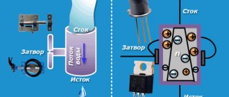
- field. There is only one type of conductor - a narrow channel subject to the electric field of a separate gate passage. Control is based on modulating the number of volts between it and the source. And between the latter and the drain an electric current flows (2 working contacts). The value has a strength depending on the signals generated between the gate (control contact) and one of the specified parts. There are products with a pn control section (working contacts are connected to a p- or n-semiconductor) or with separate gates.
Field workers have polarity options; low voltage is required for control; due to their efficiency, they are installed in radio circuits with low-power power supplies. Bipolar variants are activated by currents. In analog assemblies, the latter (BT, BJT) prevail, in digital (processors, computers) - the former. There are also hybrids - IGBTs, used in power circuits.
How to use a multimeter?
A multimeter is an electrical measuring instrument that includes many functions, such as measuring currents, voltages, resistances, and so on.
In this article I would like to tell you how to use a multimeter using the MASTECH MS8264 as an example.
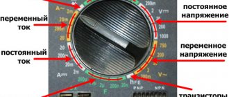
It is turned on and off with the ON/OFF button. The LIGHT button turns on the display backlight. Now we need to deal with the four nests below. The black socket is a common one, it is also a minus; when measuring with probes, we always insert a black probe into it. The socket labeled 10A - insert the red probe into it when measuring currents at the 10A limit. The second socket on the left contains a probe for measuring currents within the range of 2-200 mA, capacitance, temperature, and transistor gain. We use the rightmost socket when measuring voltages, resistances, continuity testing of diodes and circuits, as well as when measuring frequency. I categorically do not recommend leaving probes in the first two sockets, and I will explain why later.
Now let's start taking measurements. First, let's look at the DC voltmeter mode. The voltmeter is connected in parallel to the section of the circuit under study or to the power source.
With a parallel connection, the voltage is the same on all branches connected in parallel, therefore the voltage on the voltmeter and on the measured load is also the same. The input resistance between the probes is high, which allows you to measure voltages without introducing errors. Due to the high resistance of the voltmeter, there will be an open circuit when connected in series.
To change the operating modes of the device, a round rotary switch is used. The picture shows in what positions the switch can be located for the DC voltage measurement mode.
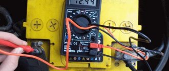
The numbers next to the dots on the dial are the measurement limits (and the letter and icon next to the group of numbers obviously show which operating mode the limits apply to), this means, for example, that at limit 20 the maximum voltage on the probes is 20 V. If you exceed this limit insignificantly (apply 20.3 V), then a unit will light up in the most significant digit, which means the measured value is higher than the set limit. However, if the measurement limit is greatly exceeded, the device may fail. Hence the rule - if the value is unknown in advance, we first measure at the highest limit. By the way, everything said now about limits applies not only to the mode of measuring direct currents, but also to all other modes. now the probes. The red probe is in the far right socket, the black one is in its personal black one. The voltmeter is connected in parallel to the section at the ends of which we measure the voltage; its input resistance is quite high. Let's try to measure the voltage on a 6V battery. We set the limit to 20, since the battery will have 6-7 V, depending on the discharge.
Under load, the voltage dropped a little, the battery was already worn out.
Earlier I said that when measuring constant current and voltage, the black conductor is “minus”, the red conductor is “plus”. However, nothing bad will happen if you change the polarity, a minus sign will appear on the screen in front of the readings and notify us that the potential of the black probe is higher than the potential of the red one.
Now the wonderful HOLD button. When you press it, the readings on the display freeze and stop changing. The H symbol on the display lights up, indicating the freezing mode. To turn off this mode, press HOLD again. The HOLD button is active in all measurement modes.
Be careful when using devices with this mode! If you accidentally press it, a situation may arise that the voltage values on the screen are low, but in reality they are deadly high. Always check if the HOLD mode is on.
Now let's try to measure alternating voltage. Now the experiment will be more dangerous - we will use a socket as a source. It contains an alternating voltage, the effective value (equivalent in effect to a direct voltage) of which is 220V, and the amplitude is about 310V (the root of 2 times the effective value). The measurement mode is shown in the picture
We select the limit 750, the highest.
Yes, when working with high voltage, try to keep one hand in your pocket. This will protect you from being shocked through your heart in an accident. Of course, this rule should not go against common sense and safety considerations.
The next frequency measurement mode. Switch in position 20 kHz. Signal 10 kHz sine. We connect the frequency meter to the terminals of the signal source.
Hmm, I was a little mistaken, and the stated error is 1.5 - 2% for this mode. (In previous measurements, I compared all the results with the DT838 multimeter, there was always a complete match.)
Now let's measure the resistance of the 1 kOhm +/-5% resistor. The multimeter must be in ohmmeter mode. An ohmmeter combines a voltmeter and an ammeter. A known voltage is applied to the part, and the resistance of the part being measured is determined by the current passing through the part and the probes (Ohm's law). Possible switch positions for measuring resistance, as always, are shown in the figure.
When measuring resistance, the element must be removed from the circuit (as a last resort, you can measure it in a de-energized circuit). We place the probes on the terminals of the device and look at the resistance between them. If polarity matters, then the red probe is a plus. We will set the limit to 2k, that is, 2 kOhm. Result:
By the way, at the limit of 200 there is a continuity function (it is indicated by a symbol that looks like a bunch of brackets); if there is a short circuit between the probes, a squeak will be heard. This helps to search for faults without looking at the screen. When measuring low resistances, keep in mind that the probes themselves introduce error because they have resistance.
When measuring large resistances, you should not touch the probes with your hands - our body also has resistance and will introduce an error into the measurement result.
Diode testing mode. Helps check the health of the diode. The screen shows the voltage drop across the pn junction in volts. In this case, the potential of the black wire is, as always, lower than the potential of the red one. An example of checking a working diode D245. Forward bias, diode open, drop 0.481 V
Reverse bias, diode closed, high voltage drop.
Let's consider the ammeter mode. Our device can measure alternating and direct currents up to 10 A. The ammeter is connected in series to the open circuit.
It has very low input impedance, so turning it on does not affect the circuit. Never connect the ammeter directly to a voltage source. This will be tantamount to a short circuit. It doesn’t matter what burns out faster - the source or the measuring device. The main thing is that something will burn. This error is especially dangerous with sources such as batteries and especially sockets. their short circuit current is very high, it will go through the multimeter and may harm the person measuring it. Let me remind you that I recommended not leaving the red probe in the first or second socket. These are current measurement inputs, their resistance is very small. If you accidentally forget to return the probe to connector 4 when measuring voltage, the effect described above may occur. Those who are used to using testers, where there is a separate connector only for 10A, and almost always the probe is in the main connector, should be especially careful.
Now let's measure direct and alternating currents at a limit of 10A. We place the probe in the first socket on the left. First, we set the limit to 10 A DC (the ten that is lower). We will measure the current in a flashlight bulb that says 6V 0.28A. Battery source 6V. The red probe, as usual, is positive, the black one is negative.
Result:
.
Now, as usual, a dangerous experiment. The current in the light bulb is 220 V 60 W. Let's first evaluate the result. Let me remind you CURRENT = POWER / VOLTAGE) 60 / 220 = 0.27 (A) Result:
For the first few seconds it was clearly 0.27, then the spiral apparently warmed up. But still, our calculation is correct.
Let's now try to calculate the current for a 1 kOhm resistor connected to our battery. I = U/R 6.2 V / 1000 Ohm = 6.2 mA. Now let's check the measurements. To measure at milliampere limits, place the probe in the second socket from the left. Total
Oops, you guessed it...
The next in line is the mode for measuring capacitance of capacitors.
In this mode, the capacitor to be measured is connected directly to the input of the device. When measuring large capacities, probes can be used. We just apply them to the terminals of the capacitor and watch the readings. If we measure the capacitance of an electrolytic capacitor, then we observe the polarity - red +, black -. For small limits, the probes contribute their own capacity, so you need to measure through the multifunction connector. Although it’s more familiar and convenient for me to measure through the connector. Like this:
The experiment involved a 10 uF 25 V capacitor.
Now consider the mode for measuring the gain of transistor h21, also known as hFE. This is the gain of the transistor in a circuit with a common emitter. It is determined as the ratio of the collector current to the base current. The multimeter takes measurements at a collector-emitter voltage of 2.8V (actually 2.58V). To measure this parameter, set the switch to hFE mode and the transistor to the adapter. where what conductivity and pinout are indicated on the connector. And here comes a minus compared to multimeters like my DT838. In our adapter the sequence of pins is strict collector-base emitter. Because of this, it is not so easy to install a KT315 type transistor with E-K-b pinout. (In the DT838, this problem is solved - the emitter input is located on both sides of the cartridge connector.) In our experiment, we will take the KT368 transistor for measurement; its pinout is exactly what is needed.
According to the datasheet it should be 50..300. Measurement accepted.
The last mode that we did not touch upon is temperature measurement. For this purpose, the kit includes a thermocouple, which is connected via the same universal connector. When installing a thermocouple, you need to look at the polarity; it is indicated on the thermocouple connector and the multimeter connector. To switch to thermometer mode, turn the switch to the degrees Celsius icon. The apartment is hot, the multimeter readings are quite correct.
In conclusion, let me remind you of the basic rules. We place the ammeter in series in the open circuit, the voltmeter in parallel. It is prohibited to connect the ammeter directly to voltage sources!
Tags:
- Multimeter
- Mastech MS8264
Checking bipolar types
Below is a diagram for checking npn, pnp transistors with a tester, after which we will describe the procedure point by point.
The bipolar transistor is equipped with pn lines - conventionally, these are diodes, or rather, 2 of them located oppositely, the point of their intersection is the “base”.
One conditional diode is designed with base/collector contacts, the other with base/emitter contacts. For analysis, just look at the contrast. (directly and back) of the indicated areas: if there are no problems there, then the part is without flaws.
Do-it-yourself testing without soldering a bipolar pnp, npn transistor involves testing 3 combinations of legs:
pnp option
Structures (types) are shown by the arrow emitting. section: pnp/npn (to/from the base). Let's start by checking the first option. We open the PNP part by applying negative voltage to the base. On the multimeter, we set the selector to measure Ohms to o; it is also possible to set it to “continuity”.
The vein “−” (black) is on the base leg. Plus (red) - alternately to collect., emitter. If the areas are not damaged, they will display about 500–1200 Ohms.
Next we will describe how to ring the reverse resistance: “+” - to the base, “−” - to the call. and emits. High resistance should be displayed. on both pn sites. We now have “1”, that is, for the frame set to “2000” the value exceeds 2000. This means that there are 2 transitions without breaks, the product is in good working order.
Similarly, as described, you can test the transistor for serviceability without removing it from the circuit. Less commonly, there are assemblies where substantial shunting is applied to the transitions, for example, with resistors. Then, if too low resistance is displayed, the part will need to be desoldered.
npn structure
Npn elements are checked in the same way, only the “+” probe goes to the base from the tester.
Symptoms of a problem
If the resistance (direct and reverse) of one of the sections (pn) tends to infinity, that is, at o and above on the display “1”, which means that this section has a break, the transistor is unusable. If “0” means the product is also flawed, the area is broken. Direct cont. there should be 500–1200 ohms.
About the transistor
Let's remember that regardless of whether we are testing a transistor with forward or reverse conduction, they have two pn junctions. Any of these transitions can be compared to a diode. Based on this, we can confidently say that a transistor is a pair of diodes connected in parallel, and the place where they are connected is the base.
Thus, it turns out that for one of the diodes the leads will represent the base and collector, and for the second diode the leads will represent the base and emitter, or vice versa. The table below shows the color and code markings of low-power mid-frequency and high-frequency transistors.
Labeling table for low-power mid-frequency and high-frequency transistors.
Based on what was written above, our task comes down to checking the drop voltage on a semiconductor device, or checking its resistance.
If the diodes are operational, then the element being tested is working. First, let’s consider a transistor with reverse conductivity, that is, having an NPN conductivity structure.
On electrical circuits of various devices, the structure of the transistor is determined using an arrow that indicates the emitter junction.
So if the arrow points to the base, then we are dealing with a forward conduction transistor having a pnp structure, and if on the contrary, then it is a reverse conduction transistor having an npn structure.
There are special probes for this, and even the multimeter itself has a socket for testing transistors, but, in my opinion, all of them are not entirely practical. To select a pair of transistors with the same gain (h21e), probes are a very necessary thing. And to determine serviceability, an ordinary cartoon will be enough.
To open a direct conduction transistor, you need to apply a negative voltage to the base. To do this, take a multimeter, turn it on, and then select the continuity measurement mode, usually indicated by a symbolic image of a diode. In this mode, the device displays the voltage drop in mV. Thanks to this, we can identify a silicon or germanium diode or transistor. If the voltage drop is in the range of 200-400 mV, then we have a germanium semiconductor, and if it is 500-700, a silicon one.
Modern multifunctional multimeter.
Checking the functionality of the transistor
We connect a positive probe (red) to the base of the field-effect transistor, connect another probe (black - minus) to the collector terminal and take a measurement. Then we connect the negative probe to the emitter terminal and measure. If the transistor junctions are not broken, then the voltage drop across the collector and emitter junction should be on the border from 200 to 700 mV.
It will be interesting➡ How to check the thyristor for performance?
To do this, we take and connect the black probe to the base, and connect the red one in turn to the emitter and collector, taking measurements.
Now let's make a reverse measurement of the collector and emitter junction.
During the measurement, the number “1” will be displayed on the device screen, which in turn means that in the measurement mode we have chosen, there is no voltage drop.
In the same way, you can check an element that is located on an electronic board from any device.
However, in many cases you can do without desoldering it from the board.
There are cases when soldered elements in a circuit are greatly influenced by low-resistance resistors.
But such schematic solutions are very rare. In such cases, when measuring the reverse collector and emitter junction, the values on the device will be low, and then you need to unsolder the element from the printed circuit board. The method for checking the functionality of an element with reverse conductivity (PNP junction) is exactly the same, only the negative probe of the measuring device is connected to the base of the element.
Where is the base, collector, emitter
We determine the base leg (the mode is the same - “2000 Ohms”): “+” of the tester we touch the left contact, “−” - the rest one by one.
Legs left/middle “1”, left/right - 816 Ohms. So far this is not very informative. Use the “+” probe for the middle contact, “−” for the rest.
The result is similar. The next stage: “+” on the right leg, “−” on the middle and then on the left.
We get “1” each, that is, resistance. is the same in these areas and it goes to infinity. It turns out that we measured the inverse of this value on both pn segments. So the base is the right leg. But the complete procedure for checking serviceability involves finding a call. and emits. direct resistance measurements We touch the base output with a minus, and the rest with a “+”.
The leg on the left is 816 Ohm, this is emitter, the middle leg is 807 Ohm, this is collector, the value there is always lower.
The result is this:
- available type - pnp;
- base on the right, em. - left; coll. - in the middle.
Signs of trouble
Now we know how to determine a working transistor, but how to check a transistor with a multimeter and find out that it is not working? Here, too, everything is quite easy and simple. The first malfunction of the element is expressed in the absence of a voltage drop or in an infinitely large resistance of the direct and reverse pn junction.
That is, when dialing, the device shows “1”. This means that the measured transition is open and the element is not working. Another malfunction of the element is expressed in the presence of a large voltage drop on the semiconductor (the device usually beeps), or near zero resistance values of the forward and reverse pn junctions. In this case, the internal structure of the element is broken (short-circuited), and it is not working.
Determining the pinout of a transistor
Now let's learn how to determine where the base, emitter and collector are located on a transistor. First of all, they begin to look for the base of the element. To do this, turn on the multimeter in dialing mode.
We attach the positive probe to the left leg, and with the negative probe we sequentially measure on the middle and right leg. The multimeter showed us “1” between the left and middle legs, and between the left and right legs the readings were 555 mV.
So far, these measurements do not allow us to draw any conclusions. Let's move forward. We fix the positive probe on the middle leg, and sequentially measure with the minus probe on the left and right legs. The toaster showed a value of "1" between the left and middle legs, and 551 mV between the middle and right legs.
Testing the diode with a multimeter.
These measurements also do not make it possible to draw a conclusion and determine the base. Let's move on. We fix the plus probe on the right leg, and with the minus probe we fix the middle and left leg in turn, while taking measurements. During the measurement, we see that the voltage drop between the right and middle legs is equal to one, and between the right and left legs is also equal to one (infinity). Thus, we have found the base of the transistor, and it is located on the right leg.
It will be interesting➡ Checking the LED with a tester
Now we just have to determine which leg is the collector and which leg is the emitter. To do this, the device should be switched to measuring resistance of 200 kOhm. We measure on the middle and left leg, for which we will fix the probe with a minus on the right leg (base), and we will fix the positive one in turn on the middle and left legs, while measuring the resistance.
Having received the measurements, we see that on the left leg R = 121.0 kOhm, and on the middle leg R = 116.4 kOhm. You should remember once and for all, if you subsequently check and find the emitter and collector, that the resistance of the collector junction is in all cases less than the resistance of the emitter.
Checking field effect transistors
Continuity, without desoldering, of the field-effect transistor, similar to that for an unmounted copy. Field workers are sensitive to static - before the event it is removed by grounding. It is enough to touch the spare part with one hand and the heating batteries with the other. To check field-effect transistors, their pinout is determined before the procedure.
Markers by which you can determine the conclusions (not always available, especially on domestic products): S - source, D - drain, G - gate. They also look at the technical documentation; the data is available on the Internet.
How to test a field effect transistor:
- We remove the static.
- We set the mode for semiconductors (“dialing”).
- We insert the red “+” wire and the black “–” wire into the corresponding sockets of the multimeter.
- “+” to the source, “−” to the drain. Operating condition: 0.5–0.7 V.
- We change the probes. If the numbers go to infinity, the transistor is working.
- “+” to the gate, “−” to the source, opening occurs. We do not disconnect the last wire, the first one goes to the drain. A working copy will show 0–800 mV. We change the polarity of the wires - the values should not change.
- We close: “−” - to the gate, “+” - to the source.
The serviceability of the field switch is determined by its opening/closing (whether this is observed at all) by applying a low voltage from the tester. The input capacitance in the element is large, and it takes a certain time to discharge. This is important, since first the multimeter opens with a small voltage (item 4), and then measurements must be taken within a short period (items 6, 7).
The procedure for checking a field-effect transistor of type p is the same as for n, only you need to connect the red probe to “−” and the black probe to “+”, that is, change the polarity.
How to check a transistor without unsoldering it from the installation
You can check the transistor with a multimeter after checking the circuit to identify possible short-circuiting of the terminals of the element being tested with low-resistance resistors. If any are found, the part will have to be removed to check. If not, the check is performed using the methods described above, but the reliability of the testing will be low. Sometimes desoldering the base output is enough.
It is better to check field-effect transistors separately from the board. They are very sensitive to static electricity, so it is necessary to use an antistatic wrist strap.
Composite transistors
To test a composite transistor, you need to turn it on. It is convenient to use a pointer tester installed for resistance analysis. (1000 or 2000 Ohm). For the npn type: probe “+” - for the collector, negative - for the emitter. For pnp it's the other way around. The arrow will be indestructible (at the beginning of the “infinity” section), and in the digital multimeter “1”. If you moisten your finger and make a short circuit, touch it to the leg of the base and the commutator, the arrow will move, as the part will open slightly. The serviceability of the transistor is confirmed.
Sziklai pair and cascode circuit
Another name for a compound semiconductor triode is a Darlington pair. In addition to her, there is also a couple of Siklai. This is a similar combination of a dyad of basic elements, which differs in that it includes different types of transistors.
As for the cascode circuit, this is also a variant of a composite transistor, in which one semiconductor triode is connected according to a circuit with an OE, and the other according to a circuit with an OB. Such a device is similar to a simple transistor, which is included in a circuit with an OE, but has better frequency characteristics, high input impedance and a large linear range with less distortion of the transmitted signal.
IGBT test
IGBTs have an insulated gate and are 3-electrode power semiconductor elements. Here, 2 transients are connected in cascade. in 1 structure: field and bipolar (control and power channels).
You can analyze the transistor on the board and soldered using a similar method. The tester is used to analyze semiconductors (“continuity”, diode icon) or resistance. 2000 Ohm. Then the resistance is measured. in the emitter/gate section straight and back. This way we will identify the short circuit, if there is one. Next, the red wire is connected to the emitter, the black wire is briefly touched to the shutter. The latter is charged with negative voltage, the transistor remains closed.
The next point is to confirm functionality. The gate-emitter input section is charged with positive voltage: at the same time, the red conductor is briefly touched to the gate, and the black conductor is briefly touched to the emitter.
Next, we check the transition point between the calls. and emitter: red wire to the first, black to the other. If a slight drop in value of 0.5–1.5 V is displayed and the value lasts for several seconds. stable, then input. The capacity is intact, the transistor is working.
Testing powerful high-voltage transistors has a peculiarity. If the multimeter voltage is not enough to open the IGBT, then 9–15 V sources are used to charge it at the output, for example, a 9 V Krona battery.
How to test a transistor without a multimeter
Testing a transistor without using a multimeter is not always possible. The use of light bulbs and power supplies in measurements can with a high probability damage the element being tested.
Checking a bipolar transistor can be done with a simple test using a 4.5 V battery, the negative of which is connected to a light bulb from a flashlight. Connect the “plus” and the second contact of the lamp to the terminals in pairs. If, when connected in any polarity to the “K-E” pair, the lamp does not light up, the transition is working. Connect through a limiting resistor “plus” to “B”. We alternately connect the lamp to terminals “E” or “K” and check these transitions. To test a transistor of a different structure, we change the polarity of the connection.
To test transistors, it is effective to use hand-made devices whose circuits are fairly accessible.
Digital transistors
A digital transistor is a special type, there are specifics on how to check it correctly.
The components of digital transistors are resistors. (R1 and 2), their rating is the same (10, 22, 47 kOhm) or mixed, different. Externally, the product has a normal appearance, but when ringing, significant differences arise.
A convenient device for checking transistors is an ampere-voltmeter, you can also take a multimeter. When the direction is direct, when the segment is open, resistance will appear on the tester. approximately comparable to the base resist. R1. When changing the polarity of the probes, the base/emitter point. closed, current flows through resistors connected in series. R1 (10 kOhm) and 2 (22 kOhm), the display will show the sum of their resistances, in our example 32 kOhm.
Base-issue segment. (VD2) is shunted by resistor R2. The resistance there should be approximately 10 times lower than R2, and when the polarity of the AVOmeter is changed, it should be infinitely greater.
Check on board
To check the transistor with a multimeter without desoldering, you need a multimeter with a diode continuity function. We move the switch to this position, the connection of the probes is standard: black to the common link (COM or with a ground symbol), red to the middle (socket for measuring resistance, current, voltage).
How to check a transistor with a multimeter without desoldering
To understand the principle of testing, we need to remember the structure of bipolar transistors. As already mentioned, they come in two types: PNP and NPN. That is, these are three consecutive areas with two transitions, united by a common area - the base.
The structure of a bipolar transistor and how it can be represented in order to understand how we will test it
Conventionally, we can imagine this device as two diodes. In the case of the PNP type they are turned on towards each other, in the case of NPN they are in mirror image. This representation is in the picture in the right column and in no way reflects the structure of this semiconductor device, but explains what we should see when making a call.
Testing a PNP type bipolar transistor
So, let's start by checking the PNP type bipolar. This is what we should get:
- If you apply a plus (red probe) to the base and a minus (black probe) to the emitter or collector, there should be an infinitely large resistance. In this case, the diodes are closed (see the equivalent circuit).
- If we apply minus to the base (black probe), and plus to the emitter or collector (red probe), we see a current from 600 to 800 mV. In this case, it turns out that the transition is open.
Checking a bipolar PNP transistor with a multimeter
So, the PNP transistor will be open only when positive is applied to the emitter or collector. If there are any deviations during testing, the element is inoperable.
Testing the serviceability of the NPN transistor
As you can see, in an NPN device the situation will be different. In practice it is diametrically opposite:
- If you apply a plus (red probe) to the base, and a minus to the emitter or collector, the junction will be open, and readings will appear on the screen - from 600 to 800 mV.
- If you swap the probes: plus to the collector or emitter, minus to the base, the transitions are locked, there is no current.
- When touching the emitter and collector with the probes, there should still be no current.
Checking the functionality of a bipolar NPN transistor with a multimeter
As you can see, this device works in the opposite direction. In order to understand whether a transistor is working or not, you need to know its type. This is the only way we can check the transistor with a multimeter without desoldering it from the board.
And once again we draw your attention to the fact that pictures with diodes do not in any way reflect the design of this semiconductor device. They are needed only to understand what we should see when checking transitions. This makes it easier to remember and understand the readings on the multimeter screen.
Thyristor testing
Let's also consider how to ring thyristors; they are in many ways similar to the parts under consideration. There are 3 pn segments, but the mode does not change after the control signal - this is the difference. The structures run alternately like stripes on a zebra crossing. Thyristor is open until the flow value drops “to the holding current”. Such details allow you to create economical circuits.
The multimeter is set to 2000 ohms. To open the thyristor being tested, the black wire goes to the cathode, the red wire goes to the anode. The part opens with both a “+” and “−” charge. In two cases, resistance must be less than "1". The part is open if the value of the control pulse exceeds the holding frame; if it is less, the key is closed.
Instead of an epilogue.
A few comments on low-power bipolar transistors (it’s not for nothing that I provided modes for them?). For some reason, radio amateurs, when building amplifiers using transistors, pay the greatest attention (and then in the best case) to the selection of identical specimens for the final stage.
Meanwhile, differential cascades or less often push-pull cascades . At the same time, it is completely forgotten that in order to receive from the differential. cascade, as well as from a push-pull cascade, to maximize all its wonderful properties, the transistors in such a cascade must also be selected !
Moreover, to ensure the closest possible temperature conditions, it is better to glue the housings of the differential cascade transistors together (or press them together with a clamp), rather than spreading them on different sides of the board. The use of integrated transistor assemblies in the input stage eliminates these problems, but such assemblies are sometimes expensive or simply not available to radio amateurs.
Therefore, the selection of low-power transistors for the input stage remains an urgent task, and the proposed device for testing transistors can significantly facilitate this process. Moreover, one of the modes chosen for measurement, a current of 5 mA, is most often the quiescent current of the first stage. And at what current does the Chinese multimeter measure???
Happy creativity!
Editor-in-Chief of RadioGazeta.
Assembling a makeshift sampler
A homemade device (probe) will allow you to instantly determine the serviceability of a transistor of any type. Let us present an elementary effective scheme.
What you will need (3 working components in total):
- the basis is any small downshift. (from pulsed power supplies, ballast for housekeeper light bulbs, small electrical appliances). Our primary has 24 turns with a middle tap; secondary - 15;
- further, 2 elements. The LED is connected to the secondary through a resistor. 100 Ohm, its power is not important, as is the polarity of the first element, since a variable value appears at the output.
There is also a slot for inserting parts to be tested according to the pinout. For bipolar straight-through types (KT 814...818 and so on), the base goes through a resist. to one of the transform contacts, medium output. which (tap) is connected to the “+” power supply. Emit. connect to “−” power supply, collection. - to have a free day off. primary If the conductivity of the part is reversed, then simply change “+” and “−”. Similarly with field workers, the main thing is to maintain the pinout. If light appears after power is applied, then the product is working.
The probe is powered from 3.7–6 V; a lead or lithium-ion battery is suitable.
Instead of a prologue.
When assembling or repairing audio amplifiers, quite often it is necessary to select pairs of bipolar transistors .
Chinese digital testers can measure the base current transfer coefficient (popularly known as the gain) of a low-power bipolar transistor. Suitable for differential or push-pull input stages. What about a powerful weekend? For these purposes, in the measuring laboratory of a radio amateur engaged in the design or repair of amplifiers, there must be a device for testing transistors . It must measure the gain at high currents close to operating currents.
For reference: the gain of the transistor “scientifically” is called the coefficient of transfer of the base current to the emitter circuit, denoted h21e. Previously it was called “beta” and designated as β, so sometimes old-school radio amateurs the device for testing transistors “betnik”.
On the Internet and amateur radio literature you can find a huge number of options for device circuits for testing transistors . Both quite simple and complex, designed for different modes or automation of the measurement process.
For self-assembly, it was decided to choose a simpler circuit so that our readers could easily make a device for testing transistors with their own hands . Let us note right away that we somehow more often have to deal with amplifiers based on bipolar transistors , therefore the resulting device is designed to measure the parameters of bipolar transistors .
For reference: previously, the editor-in-chief of RadioGazeta carried out measurements in the old-fashioned way: two multimeters (in the base circuit and the emitter circuit) and a “multi-turn” to set the current. Long, but informative - you can not only select transistors, but also remove the dependence of h21e on the collector current. Quite quickly, the realization of the futility of this activity came: for our transistors, removing such a dependence is one frustration (they are so crooked), for imported ones it is a waste of time (all graphs are in the datasheets).
Turning on the soldering iron, the editor-in-chief began to assemble a device for testing transistors with his own hands.
Bottom line
Any transistor is checked with a multimeter. You need to find out the purpose of its legs (base/col./emitter, drain/source/gate). Next, set the tester to “continuity” or to the 2000 Ohm mark. Then analyze forward and reverse resistance. Based on the result, you can determine the performance of the transistor. You can also analyze the coefficient. amplification: the tester has a special socket and an hFE mark.
Basic types of transistors
There are two main types of transistors - bipolar and field-effect. In the first case, the output current is created with the participation of carriers of both signs (holes and electrons), and in the second case - only one. Testing the transistor with a multimeter will help determine the malfunction of each of them.
Bipolar transistors are essentially semiconductor devices. They are equipped with three pins and two pn junctions. The operating principle of these devices involves the use of positive and negative charges - holes and electrons. Flowing currents are controlled using a specially dedicated control current. These devices are widely used in electronic and radio engineering circuits.
Bipolar transistors consist of three-layer semiconductors of two types - “p-p-p” and “p-p-p”. In addition, the design has two pn junctions. The semiconductor layers are connected to external terminals through non-rectifying semiconductor contacts. The middle layer is considered the base, which is connected to the corresponding pin. Two layers located at the edges are also connected to the outputs - the emitter and collector. In electrical circuits, an arrow is used to indicate the emitter, indicating the direction of current flowing through the transistor.
In different types of transistors, holes and electrons - carriers of electricity - can have their own functions. The most common type is p-p-p due to the best parameters and technical characteristics. The leading role in such devices is played by electrons, which perform the main tasks of ensuring all electrical processes. They are approximately 2-3 times more mobile than holes, and therefore have increased activity. Qualitative improvements in devices also occur due to the collector junction area, which is significantly larger than the emitter junction area.
Each bipolar transistor has two pn junctions. When testing a transistor with a multimeter, this allows you to check the performance of the devices by monitoring the resistance values of the transitions when direct and reverse voltages are connected to them. For normal operation of the p-p-p-device, a positive voltage is applied to the collector, under the influence of which the base junction opens. After the base current occurs, the collector current appears. When a negative voltage occurs in the base, the transistor closes and the current flow stops.
The base junction in pnp devices opens when exposed to negative collector voltage. Positive voltage causes the transistor to turn off. All the necessary collector characteristics at the output can be obtained by smoothly changing the current and voltage values. This allows you to effectively test the bipolar transistor with a tester.
There are electronic devices in which all processes are controlled by the action of an electric field directed perpendicular to the current. These devices are called field-effect or unipolar transistors. The main elements are three contacts - source, drain and gate. The design of the field-effect transistor is complemented by a conductive layer that acts as a channel through which electric current flows.
These devices are represented by modifications of the “p” or “p”-channel type. Channels can be located vertically or horizontally, and their configuration can be volumetric or near-surface. The latter option is also divided into inversion layers containing enriched and depleted ones. The formation of all channels occurs under the influence of an external electric field. Devices with near-surface channels have a metal-dielectric-semiconductor structure, which is why they are called MOS transistors.