Microcontrollers / For Beginners /
| What is needed to become a professional program developer for microcontrollers and reach a level of skill that will allow you to easily find and get a job with a high salary (the average salary of a microcontroller programmer in Russia at the beginning of 2022 is 80,000 rubles). Read more… |
As you understand, powerful and/or high-voltage loads (such as incandescent lamps, electric motors, electric heating elements, etc.) cannot be directly connected to the output of the microcontroller. Because the microcontroller outputs:
- Not designed to operate with high voltage.
- Not designed to drive heavy loads (loads that draw a lot of current).
- They do not have galvanic isolation (sometimes this is important even when controlling a low-current load).
It follows from this that in order to control a powerful load using a microcontroller, it is necessary to use some clever methods of pairing the microcontroller outputs with the load. There are several of these methods:
- Load connection via optocoupler
- Connecting the load through a transistor.
- Connecting the load via an electromagnetic relay.
- Load connection via solid state relay.
These types of connections will be discussed in more detail in the relevant articles. And here I will only talk about the advantages and disadvantages of these methods.
Load connection via optocoupler
So, one of the simplest ways is to connect through an optocoupler (photosemistor, photothyristor, etc.).
This method is suitable for controlling active loads such as incandescent lamps, electric heaters, etc. Its advantages are the presence of galvanic isolation, relative ease of connection and low cost of optocouplers. There is, perhaps, only one serious drawback. But quite significant - when controlling an inductive load, such as electric motors, the triac/thyristor of the optocoupler can spontaneously open (without a command from the microcontroller). So for such a case, you will have to take additional measures to complicate the device on the microcontroller.
Another disadvantage is that to use an optocoupler you need to have at least a little understanding of electronics.
Input protection: voltage
Not all input devices will be friendly to your microcontroller, and some sources may even be harmful. If you have input sources that come from the environment (eg voltage sensor, rain sensor, human contact) or input sources that can output voltages higher than what the microcontroller can handle (eg inductor circuits), then you will need to include some voltage input protection. The circuit shown below uses 5V zener diodes to limit input voltages so that the input voltage cannot go above 5V and below 0V. A 100R resistor is used to prevent too much current flow when the Zener diode captures the input voltage.
Example of voltage input protection
Connecting a load via a transistor
It's also quite simple to do. The cost of conventional transistors is also relatively low. That's a plus.
Cons - you can only control a DC load (we are talking about cheap bipolar transistors). Moreover, the load voltage should also be as low as possible. Because high-voltage transistors are no longer very cheap (and some are very expensive).
Another drawback is the lack of galvanic isolation between the load and the microcontroller output.
And, just as in the case of an optocoupler, you need to have at least a little understanding of electronics in order to select the right transistor and calculate the circuit diagram for switching on the transistor itself and additional resistors.
§ 38. Using PWM. Connecting field effect transistors. |
| Kiselev Roman, June 2007 |
| Article updated May 26, 2014 |
| Files for the article |
| In this article we will look at the issues of adjusting the power of various devices connected through a field-effect transistor to the MK using pulse width modulation (PWM). |
First, a little theory. PWM is a method widely used in electronics to regulate the power of a wide variety of devices. Where else has it not found application! The method involves briefly turning on the device (for a fraction of a millisecond), and then turning it off for a certain point in time. This on-off cycle is continuously repeated. Consider the diagram below.
The diagram shows the dependence of load voltage on time. The gray area is the area when the PWM controlled device was turned on. The energy released can be considered proportional to the area of this region. The ratio of the pulse repetition period (T) to their duration (AC) is called duty cycle
.
The reciprocal of the duty cycle is called duty cycle
. Judging by the diagram, the duty cycle is greatest in the middle of the diagram. This means that in this section the least amount of energy was released at the load per unit time. I hope this is all clear. But the question arises: why is PWM so good? Why not use a device that can change resistance (variable resistor or transistor) to regulate power? Let's consider two seemingly equivalent circuits.
If you change the resistance of the resistor, as shown in the graph in the center, and apply the PWM sequence shown in the diagram to the key element of the right circuit, then the light bulbs will shine the same at any time (UL is the voltage across the light bulb). But in the right circuit, energy will be released only in the light bulb, and in the left circuit, both in the light bulb and in the resistor (or transistor, which can successfully replace it). The resistor will heat up, and perhaps no worse than a light bulb. Therefore, when asked which scheme is more rational, I think anyone will answer that it is the right one. It is called pulsed, and the left circuit is called linear. When working with powerful high-current electronics, they always give preference to pulsed elements and methods. Linear ones are used only where low powers and low currents are controlled. Moreover, in digital electronics, where there are only two states - “on” and “off”, PWM is much easier to implement. This is what we will do in this article.
To do this, we need very little - a field-effect transistor, which will work as a key for us (in switching mode). A field-effect transistor is preferable because its gate is isolated from the power circuit and is controlled by an electric field, and the control current reaches microamps. This allows, using one or two transistors, to control with their help a load of enormous power (up to tens of amperes and tens of hundreds of volts), without loading the MK. Wonderful, powerful and inexpensive (10 - 30 rubles) transistors are produced by International Rectifier. They are called IRFxxxx, where xxxx is a three or four digit number. I used IRF7311 in my development board. Others similar to it are also suitable: IRF7341, IRF7103 IRF7301, IRF7343, IRF7401, IRF7403, IRF7413... These transistors are controlled by the logical level of +5 V, i.e. our MK will be enough to fully open them. They, in turn, can control voltages from 20 V (all) to 50 V (IRF7103, IRF7341) and through them it will be possible to open and close more powerful transistors with a sufficiently high control voltage, for example, IRF530. Thus, it is possible to assemble a very powerful high-speed cascade using field-effect transistors, capable of smoothly changing the power at the load using PWM, switching currents of tens of amperes. Taking into account also the fact that field-effect transistors can be connected in parallel (unlike bipolar ones), it is possible to obtain an even more powerful cascade of hundreds of amperes.
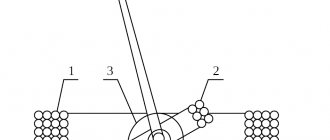
So, let's say you decide to buy the IRF7311. If you open its Datasheet (available in the files for the article), you find out the following: this is a tiny microcircuit in an SO-8 package, inside of which there are two field-effect transistors with an N-type induced channel and built-in Schottky diodes. This means that in order to open the transistor, a control voltage of +5 V must be applied to the gate G (Gate) relative to the source S (Source). Then, if a switched voltage was applied “plus” to the drain D (Drain) and “minus” to the source, then a fairly strong current (up to 6 A) will flow from D to S. The presence of a Schottky diode allows, without fear of EMF self-induction, use these transistors to control electric motors. Below is the pinout of the transistor and its appearance:
There should be a point on the top of the body in the corner, the same as in the picture. It stands next to “leg” 1. By the way, for all microcircuits, the “legs” are numbered starting from a similar mark counterclockwise, when viewed from above - in case someone doesn’t know... If you bought a field-effect transistor with a P-channel, it’s okay. Then you will have to apply a “minus” to G (relative to S) to turn it on and change the load polarity. That is, for any field-effect transistor with an induced gate, you need to supply current against the arrow located between the gate and the diode, and connect the load so that the current flows through it in the direction opposite to the built-in diode. That's all.
Let us now attach our transistor IRF7311 with a gate to the 21 “legs” of the MK (PD7, OC2
) and the source to the “ground”. We connect the “plus” of an external power source (up to 20 V) to its drain, and connect a load, for example, a light bulb or a DC electric motor, between its “minus” and the source.
When I assembled everything, it turned out like this (although the wires are not visible, the light bulb is connected):
All that remains is to figure out how the MK implements PWM and write a program. As mentioned earlier, our MK has 3 timers, and all of them can operate in PWM mode. Timer1 is the most sophisticated and can output PWM on two MK pins at once. But we will not go into details and complications that are unnecessary for us for now and will consider working with PWM using the example of timer 2.
There are two modes of operation of the timer as a PWM modulator. These are Fast PWM (fast PWM) and Phase correct PWM (PWM with phase correction). Let's look at both modes in the following diagrams:
The operating mode is determined by the contents of the WGM (Waveform Generation Mode) bits in the TCCR2 register. The Datasheet says that for PWM with phase correction you need to set WGM20 to one, and for fast PWM WGM20 and WGM21. How are these modes different? In fast mode, the state of the “leg” of OC2 changes at the moments when the counting register TCNT2 and the comparison register OCR2 coincide (green arrow), as well as at the moment the timer is reset (blue arrow). In this case, the middle of the pulse (orange) seems to shift to the left, the phase of the pulse changes . In the phase correction mode, this phenomenon is not observed. In this mode, the timer, having counted to the maximum (up to 255), begins counting in the other direction. When the TCNT2 and OCR2 registers coincide, the state of the OC2 pin changes. In this case, the center of the pulse does not shift anywhere. This mode has half the frequency of the fast mode, but the manufacturer claims that it is better suited for controlling electric motors (most likely stepper ones). Fast mode can be used in any other cases. All other timers work in the PWM mode in the same way; timer1 also allows you to change the PWM period in an arbitrary way, but I think this is of no use to us.
Everything seems to be clear with the theory now.
Let's open IAR, create a new project, type the following code: #include
“iom16.h” unsigned char pwm = 1;
unsigned char inc = 1; // inc = 0 — decrease, inc = 1 — increase brightness void
timer2_init() { OCR2 = 1;
//PWM almost off // Fast PWM, switch OC2 (PD7), increase the timer every 64 clock cycles
TCCR2 |= (1 void timer1_init() { OCR1A = 43200;
// Interrupt 32 times per second
TCCR1A = 0;
// CTC mode , increment the timer every 8 clock cycles
TCCR1B |= (1 // Interrupt on coincidence A of timer1 TIMSK |= (1 //Enable interrupts }
void
io_init()
//Initialize I/O ports
{ DDRD = (1 void main () { timer2_init (); timer1_init(); io_init(); while(1) { } }
// Causes the lamp to fade on and off once every 8 seconds #pragma
vector = TIMER1_COMPA_vect
__interrupt void
PWM_change() {
if
(inc == 1) {
if
(pwm // Increase the brightness of the lamp until we reach the maximum OCR2 = pwm; }
else
{ inc = 0; } }
else
{
if
(pwm > 1) { pwm—;
// Decrease the brightness of the lamp until we reach the minimum
OCR2 = pwm ; }
else
{ inc = 1; } } }
The timer2_init() function is used by us to enable the timer in PWM mode. The timer will increase the counting register every 64 clock cycles, operate in Fast PWM mode, changing the state of OS2 in a non-inverted manner (bits COM20, COM21). Yes, I forgot to say. These bits are responsible for the behavior of the OS2 “leg” to which the transistor is connected. The mode can be inverted or non-inverted. To understand this, look at the diagram above. There is a graph of the state of OS2 (non-inverted output) and OS2 with a line (inverted output). If both bits are set to 1, the mode will be inverted. There is one pitfall when working with PWM and using transistors: not all transistors can change their state very quickly. Some may require tens to hundreds of nanoseconds (like ours), while others may require microseconds and tens of microseconds. Therefore, I do not recommend using it at a high frequency without studying the documentation for the transistor - a large load at a high PWM frequency can burn it out.
timer1_init() turns on timer2 and causes it to do 32 interrupts per second. When an interrupt occurs, the OCR2 register changes and, accordingly, the brightness of the lamp. Thus, the lamp will smoothly light up and go out smoothly once every 8 seconds. Instead of a timer, you can connect buttons and change the brightness when they are pressed. But for clarity, everything will happen automatically.
Let's save this file in the folder with the project, add it to the project, set the project options as written in article 1, but you can now leave optimization on. The fact is that in the first article we created a delay using a loop. It is illiterate to do this from a programming point of view, and to increase the speed of the program the compiler throws out such loops. Now we use the hardware built into the MK, which does not reduce performance and speed. Therefore, optimization will not do anything bad.
Select Release, press F7, the program compiles. Launch AVReal, flash the MK. By the way, perhaps you had a question: is it possible to reflash the MK an infinite number of times? It turns out not. Only 10,000 times (at least). Therefore, I think there is absolutely no need to worry about this. After all this has been done, you can check the device.
IMPORTANT!!!
First you need to supply power to the MK, make sure that the transistor is connected to the MK, and only then supply power to the circuit with the lamp (motor) and the field-effect transistor. Otherwise you may burn out the transistor. The fact is that when turned off, the “legs” of the MK “dangle in the air” - they are not connected to anything, and interference occurs on them. These weak interferences are enough to partially open a very sensitive field-effect transistor. Then its resistance between drain and source will drop from several MOhms to several Ohms or fractions of Ohms and a large current will flow through it to the lamp. But the transistor will not open completely, because for this you need to apply not 1-3 V interference to the gate, but a stable 5 V, and its resistance will be much greater than the minimum (for IRF7311 this is 0.029 Ohm). This will cause a lot of heat to be generated on it, and it will smoke and maybe burn. Although, of course, it all depends on the power of the lamp or motor.
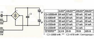
After turning on all parts of this device, you should see a picture similar to the one below. There is also an ammeter drawn there, showing the current strength in the lamp.
Instead of our circuit with a transistor and a lamp, you can simply connect an LED to pin OC2. It will smoothly change its brightness. But this, of course, is no longer so interesting.
© Kiselev Roman June 2007 https://www.kernelchip.ru
Load connection via electromagnetic relay
Connecting an electromagnetic relay is as easy as shelling pears. But this is only at first glance. In fact, there are also features that you need to know (I’ll tell you about them in the corresponding article). Otherwise, you can simply damage the output of the microcontroller.
Advantages of an electromagnetic relay:
- Low price.
- You can control a load of almost any power and voltage.
- Both DC and AC loads can be controlled.
- You can control both active and inductive loads without any additional tricks.
- There is a galvanic isolation between the microcontroller output and the load.
- No special knowledge of electronics is required to select a relay for the load.
Flaws:
- Additional measures must be taken to protect the microcontroller output.
- Relatively low speed (the relay switches much slower than semiconductor devices - sometimes this is important).
- Large dimensions and weight. Although modern relays are quite miniature, their size and weight are still larger than the size of semiconductor devices.
- Relatively low resource. Since the relay has contacts, the relay life is lower than that of semiconductors. Due to sparking, contacts fail faster. Although, as practice shows, high-quality relays can operate for decades without breakdowns.
Simple relay driver
Devices that draw more than 1A of current and will turn on and off every few seconds are better suited to relays.
Although relays are quite simple (a small electromagnet that attracts a metal lever to close a circuit), they cannot be controlled directly by a microcontroller.
Conventional relays require currents of around 60mA~100mA, which is too high for most microcontrollers, so the relays require a circuit using transistor control (as shown above). However, instead of the resistor that must be used to limit the current, a flyback protection diode (D1) is required.
When the microcontroller (connected to "IN") outputs a 1, then transistor Q1 turns on. This turns on relay RL1 and as a result the lamp (R2) lights up. If the microcontroller outputs 0, then transistor Q1 turns off, which turns off the relay and therefore the lamp turns off.
Relays are very common in circuits that require switching AC power circuits and are available to switch 230V and 13A (suitable for toasters, kettles, computers and vacuum cleaners).
Example of a simple relay driver
Load connection via solid state relay
A solid-state relay is a semiconductor device that combines, for example, a phototriac and all the wiring necessary to control it. That is, a solid-state relay can simply be connected to the output of the microcontroller, without worrying about what resistance the quenching resistors, etc. should have.
However, solid state relays are more difficult to use than conventional relays. Because solid-state relays have quite a lot of different characteristics that need to be understood. However, it is not difficult to study this topic.
A solid-state relay has perhaps only one drawback: its high price. A solid-state relay, as a rule, costs 5...10 times more than a conventional electromagnetic relay (that is, hundreds and thousands of rubles apiece).
Buttons
When connecting a button to a microcontroller, simple problems can sometimes arise. The first (and most annoying problem) occurs in the form of bounce, where the button sends a lot of signals when pressed and released.
Buttons are usually a piece of metal that makes contact with some other metal when they make contact, but when buttons make contact they often bounce back (even though they're usually tiny). This bounce means the button connects and disconnects several times before settling, resulting in a result that briefly appears random. Since microcontrollers are very fast, they can catch this bounce and execute button press events multiple times. To get rid of the rebound, you can use the diagram below. The circuit shown here is a very trivial circuit that works well and is easy to build.