Insulation resistance measurement
The resistance of the main insulation of current transformers, the insulation of the measuring capacitor and the terminal of the last lining of the paper-oil insulation of the capacitor type is measured with a 2500 V megohmmeter. The
resistance of the secondary windings and intermediate windings of cascade current transformers relative to the base is measured with a 1000 V megohmmeter.
During operation, measurements are made:
- on current transformers 3-35 kV - during repair work in the cells (connections) where they are installed;
- on 110 kV current transformers with paper-oil insulation (without equalizing plates) - in case of unsatisfactory oil test results in accordance with the requirements of Table. 25.4, paragraphs. 1-3 (area of “risk”);
- on current transformers 220 kV and above with paper-oil insulation (without equalizing plates) - in the absence of insulation control under operating voltage and unsatisfactory oil test results in accordance with the requirements of Table. 25.4, paragraphs. 1-3 (area of “risk”);
- on current transformers with paper-oil insulation of capacitor type 330 kV and above - in the absence of insulation control under operating voltage - once a year. The measured insulation resistance values must be no less than those given in table. 1.
Table 1
| Voltage class, kV | Permissible insulation resistance, MOhm, not less | ||||
| Basic insulation | Test lead | Outer layers | Secondary windings* | Intermediate windings | |
| 3-35 | 1000/500 | — | — | 50 (1)/50 (1) | — |
| 110-220 | 3000/1000 | — | — | 50 (1)/50 (1) | — |
| 330-750 | 5000/3000 | 3000/1000 | 1000/500 | 50 (1)/50 (1) | 1/1 |
*The insulation resistances of the secondary windings are given: without brackets - with the secondary circuits disconnected, in brackets - with the secondary circuits connected.
Note: The numerator indicates the insulation resistance values of current transformers during commissioning, and the denominator indicates during operation.
For cascade current transformers, the insulation resistance is measured for the current transformer as a whole. If the results of such measurements are unsatisfactory, the insulation resistance is additionally measured in stages.
6. Determination of the design load Zн
The design load for relay protection current transformers is determined using the expressions given in Table No. 1. The calculation assumes Zн=Zadd.
By the value of Zn you can determine the resistance of the connecting wires (cable cores) in the secondary circuits of current transformers.
Table 1 - calculation formulas for determining the secondary load and resistance of the connecting wires of current transformers for relay protection
Measurement of tgδ insulation
Measurements of tgδ for current transformers with main paper-oil insulation are carried out at a voltage of 10 kV. During operation, measurements are made:
- on current transformers with voltage up to 35 kV inclusive - during repair work in the cells (connections) where they are installed;
- on 110 kV current transformers with paper-oil insulation (without equalizing plates) - in case of unsatisfactory oil test results according to the requirements of Table. 25.4, paragraphs. 1-3 (area of “risk”);
- on current transformers 220 kV and higher with paper-oil insulation (without equalizing plates) - in the absence of control under operating voltage and unsatisfactory results of oil tests according to the requirements of Table. 25.4, paragraphs. 1-3 (area of “risk”);
- for current transformers with paper-oil insulation of capacitor type 330 kV and above - in the absence of control over the operating voltage - once a year.
The measured values, normalized to a temperature of 20°C, should be no more than those indicated in the table. 2. For cascade current transformers, tgδ of the main insulation is measured for the current transformer as a whole. If the results of such measurements are unsatisfactory, tgδ of the main insulation is additionally measured in stages.
table 2
| Insulation type | Limit values tgδ, %, of the main insulation of current transformers at rated voltage, kV, normalized to a temperature of 20°C | ||||||
| 3-15 | 20-35 | 110 | 220 | 330 | 500 | 750 | |
| Paper-bakelite | 3,0/12,0 | 2,5/8,0 | 2,0/5,0 | — | — | — | — |
| Basic paper-oil and capacitor insulation | — | 2,5/4,5 | 2,0/3,0 | 1,0/1,5 | No more than 150% of what was measured at the factory, but not higher than 0.8. No more than 150% of what was measured during commissioning, but not higher than 1.0. | ||
Note. The numerator indicates the tgδ values of the main insulation of current transformers during commissioning, and the denominator - during operation.
Online testing of current transformers based on the condition of 10% error
Result of calculation check of current transformers
| CT Rated Load (in Ohms) | Znom.CT, Ohm | |
| Relay resistance | Zр, Ohm | |
| Wire resistance from CT to protection device | rpr, Ohm | |
| Actual CT secondary load | Zn.calc, Ohm | |
| Actual limit factor | Kpc.fact | |
| Minimum limit factor required for a protection device | Kpk.min | |
| Check conditions | ||
| Check for 10% error | Kpc.fact ≥ Kpc.min | |
| Measurement limit test | Ik.max / Ifirst ≤ 100 | |
| The calculation was made on the website electro-engineering.ru | ||
Literature:
- Operating manuals for Siemens relay protection terminals type 7SJ80, 7SJ81, 7SJ82, 7SS85, 7UT82-85, 7SD82.
- Shabad. M.A. Calculations of relay protection and automation of distribution networks: Monograph. St. Petersburg: PEIPK, 2003.
Alexey Bobkov
Author of the article, design engineer of relay protection systems for stations and substations
High voltage test
3.1 P. High voltage test of main insulation
The test voltage values of the main insulation are given in table. 3. Test duration for current transformers with porcelain external insulation is 1 min, with organic insulation – 5 min. It is allowed to test current transformers together with the busbar. Current transformers with voltages over 35 kV are not subject to increased voltage tests.
Table 3
| Voltage class of electrical equipment, kV | Test voltage, kV | |||||
| Power transformers, shunt and arc suppression reactors | Devices, current and voltage transformers, current-limiting reactors, insulators, bushings, coupling capacitors, shielded conductors, busbars, switchgear and package transformer substations | |||||
| At the factory | During commissioning | In use | At the factory | Before commissioning and in operation | ||
| Porcelain insulation | Other types of insulation | |||||
| Up to 0.69 | 5,0/3,0 | 4,5/2,7 | 4,3/2,6 | 2,0 | 1 | 1 |
| 3 | 18,0/10,0 | 16,2/9,0 | 15,3/8,5 | 24,0 | 24,0 | 21,6 |
| 6 | 25,0/16,0 | 22,5/14,4 | 21,3/13,6 | 32,0 (37,0) | 32,0 (37,0) | 28,8 (33,3) |
| 10 | 35,0/24,0 | 31,5/21,6 | 29,8/20,4 | 42,0 (48,0) | 42,0 (48,0) | 37,8 (43,2) |
| 15 | 45,0/37,0 | 40,5/33,3 | 38,3/31,5 | 55,0 (63,0) | 55,0 (63,0) | 49,5 (56,7) |
| 20 | 55,0/50,0 | 49,5/45,0 | 46,8/42,5 | 65,0 (75,0) | 65,0 (75,0) | 58,5 (67,5) |
| 35 | 85,0 | 76,5 | 72,3 | 95,0 (120,0) | 95,0 (120,0) | 85,5 (108,0) |
3.2. High voltage test of insulation of secondary windings
The test voltage for insulating the secondary windings together with the circuits connected to them is assumed to be 1 kV. The duration of test voltage application is 1 min.
Measuring and calculating the limiting factor
When the maximum normalized indicator is exceeded, the device moves from the stable operating area to the saturation phase. The accuracy of the functional is assessed using mathematical curves, the conditions of which are given in the tables. The coefficient is not established empirically, but according to special tabular data. The curves consist of information about the largest ratio of secondary current to the average rated current supplied to the primary.
The calculation is made in such a way that the total error in the calculated data (that is, when including the specified information about the secondary load) does not exceed ten percent. Mathematical curves allow you to calculate the characteristics of wires, devices, relays, connection diagrams and create a circuit in such a way that oversaturation does not occur and the devices operate in optimal mode.
Equipment supplemented with differential protection must have an identical maximum multiplicity for through short-circuit current.
Design curves are given for calculations of work according to the established mode. If the aperiodic tends to max, that is, the mode is transitional, then the parameter reaches 70-75%.
The accuracy class is chosen depending on the purpose. The same requirements apply to devices with non-identical load types.
Removing magnetization characteristics
The characteristic is removed by increasing the voltage on one of the secondary windings until saturation begins, but not higher than 1800 V. If the windings have branches, the characteristic is removed on the working branch. During operation, only three control points can be removed. The taken characteristic is compared with the typical magnetization characteristic or with the magnetization characteristics of serviceable current transformers of the same type as those being tested. Differences from the values measured at the manufacturer or from those measured on a working current transformer of the same type as the one being tested should not exceed 10%.
ELECTROlaboratory
Good day, dear friends!
The new year 2015 has come. I hope this year will be no worse than the previous one. In general, Happy New Year, friends!
I would like to start the year with an article about current transformers. Of course, my story will be more general than scientific.
To thoroughly study the issue, I suggest using technical literature or at least
INSTRUCTIONS FOR CHECKING CURRENT TRANSFORMERS USED IN RELAY PROTECTION AND MEASUREMENT CIRCUITS (RD 153-34.0-35.301-2002).
So let's get started.
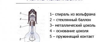
The simplest and most common current transformer (CT) is a two-winding one. It has one primary winding with the number of turns w1
and one secondary winding with the number of turns
w2
. The windings are located on a common magnetic core, due to which there is a good electromagnetic (inductive) connection between them.
The primary winding, isolated from the secondary winding at the full operating voltage of the device, is connected in series to the cut circuit of the controlled primary current, and the secondary winding is closed to the load (measuring instruments and relays), ensuring the flow of a secondary current in it, practically proportional to the alternating primary current. The lower the load impedance zн
and the total resistance of the secondary winding
zT2
, the more accurately the proportionality between the primary and secondary currents is observed, i.e. the smaller the CT error. The ideal operating mode of the CT is the short-circuit mode of the secondary winding. One terminal of the secondary winding is usually grounded, so it has a potential close to the potential of the electrical installation ground loop.
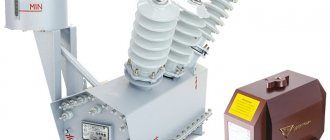
Here is the appearance of a CT up to 1000 V:
And here is the appearance of CTs above 1000 V:
Current transformers for protection are designed to transmit measuring information about primary currents to protection and automation devices. At the same time they provide:
1) large-scale conversion of alternating current of various strengths into an alternating secondary current of acceptable strength (most often 1 or 5A) to power relay protection devices;
2) isolation of secondary circuits and relays, to which maintenance personnel have access, from high voltage circuits. Similar functions are performed by CTs for measurements, designed to transmit information to measuring instruments.
There is no fundamental difference between CTs for protection and for measurements. The existing differences lie in unequal requirements for accuracy and for primary current ranges in which CT errors should not exceed permissible values. CTs for measurements are required to limit from above the effective value of the secondary current when a short-circuit current flows through the primary winding; for them, the nominal safety factor of the devices is established. This requirement does not apply to CTs for protection, which must provide the necessary accuracy of current transformation even during a short circuit. The rated safety factor is actually the upper limit for the rated CT limit factor for measurements. Therefore, in the standards of some countries (for example, in the German rules VDE 0414 “Regeln für Meßwandler”), the nominal maximum multiplicity (Nenn Überstromziffer “n”) is standardized for all CTs, and its limit for measuring CTs is given in the form n
< …, and for current transformers for protection in the form
n
>… .
When analyzing phenomena in CTs, it is necessary to take into account the positive directions of the primary and secondary currents in the corresponding windings, as well as the EMF induced in the secondary winding, on which the signs (plus or minus) in the formulas and the angles of the vectors in the vector diagrams depend.
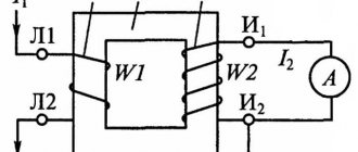
In relay protection technology, positive directions for currents and EMF are adopted, shown in Figure 1. Asterisks mark unipolar winding terminals, for example their beginnings, which according to GOST are designated by the symbols L1 for the primary winding and I1 for the secondary winding.
| A) | b) | V) |
a, b - symbol schemes; c - equivalent circuit
Figure 1 - CT circuits
Accepted positive: the direction for the primary current from the beginning to the end of the primary winding and the direction for the secondary current from the beginning of the secondary winding (along the external load circuit) to the end of the secondary winding, accordingly, inside the secondary winding - the direction of the secondary current and secondary EMF (from end to beginning windings).
In the indicated positive directions, the vectors of the primary and secondary currents are in phase in the absence of an angular error, and the instantaneous secondary EMF is equal to the first time derivative of the flux linkage of the secondary winding, taken with a plus sign.
Due to the significant nonlinearity of the magnetization characteristics of a ferromagnetic magnetic circuit, the principle of superposition (superposition) is not applicable to the analysis of phenomena in CTs. Even with a rated primary current and a rated load, the induction in the magnetic circuit is not equal to the difference in induction that would be created by the primary and secondary currents taken separately. The resulting magnetic flux in the CT magnetic circuit is determined only by the combined simultaneous action of the primary and secondary currents and, even hypothetically, cannot be correctly considered as the difference in fluxes separately created by the primary and secondary currents.
CT classification
According to GOST 7746-89, TTs are divided according to the following main characteristics:
- by type of installation:
for work outdoors (location category 1 according to GOST 15150-69 [22]);
for work in enclosed spaces (location categories 3 and 4 according to GOST 15150-69);
for work in underground installations (location category 5 according to GOST 15150-69);
for work inside electrical equipment enclosures
— according to the design principle:
support (O), pass-through (P), busbar (W), built-in (B), detachable (P). According to GOST 7746-89 [14], a combination of several listed principles is allowed, as well as a design that does not fall under the listed characteristics;
— by type of insulation:
with cast insulation (L), with porcelain cover (F), with solid insulation (except porcelain and cast) (T), oil-filled (M), gas-filled (G);
— by the number of transformation steps:
single-stage and cascade;
— by the number of magnetic cores with secondary windings,
called cores, united by a common primary winding: with one core, with several cores;
— according to the purpose of cores:
for measurement, for protection, for measurement and protection, for working with standardized accuracy in transient modes;
— by the number of transformation coefficients:
with one transformation ratio; with several transformation ratios obtained by changing the number of turns of the primary and/or secondary windings, as well as by using secondary windings with taps.
Structure of the TT symbol according to GOST 7746-89
In the standards for certain types of transformers, GOST 7746-89 [14] allows additional letters to be entered into the letter part of the designation. It is allowed to exclude or replace individual letters, except T, to indicate the features of a particular TT.
Basic (nominal) CT parameters
According to GOST 7746-89, the nominal parameters of CTs include:
— rated voltage CT Unom
- rated voltage of the circuits for which this device is intended. Built-in CTs do not have a nominal voltage rating;
— rated primary current CT I1nom
;
— rated secondary current CT I2nom
;
— rated transformation ratio of the CT (transformation ratio is the ratio of the primary rated current to the secondary one. Usually written, for example, 150/5 and then equal to 30, i.e., for any primary current, the secondary one will be thirty times less);
— rated secondary load with rated power factor cosj (1 or 0.8 inductive). Designated zn. nom
(load resistance) or
Sn.
nom (rated load power);
— nominal accuracy class of CT (core for CT with several cores) (usually for measurements the accuracy class is no worse than 0.5, and for relay protection and automation systems no worse than 10);
— nominal maximum multiplicity of the CT serving relay protection — K10nom
,
K5nom
;
— nominal safety factor for devices — K d nom
;
— rated frequency of CT — fnom
.
Testing of measuring current transformers.
The object of testing in current and voltage instrument transformers is, first of all, the transformer insulation, the transformer windings, both primary and secondary, as well as the transformer core iron.
Current transformers are manufactured with the following internal insulation design:
· Paper-bakelite (transformers TP series 6-35 kV); ceramic (current transformers 6-10 kV types TPOF, TPF, etc.).
· Cast epoxy (current transformers types TPOL, TPShL, TSHL, etc. 6-35 kV).
Scope of testing of current transformers:
1) measurement of the insulation resistance of the primary and secondary (secondary) windings (K, M)
2) high voltage test of winding insulation (M)
3) reading the magnetization characteristics of transformers (K)
4) measurement of transformation ratio (K).
Note: K – major overhaul, testing upon acceptance into operation; M – overhaul tests
Insulation resistance.
During operation, measurements are carried out:
on current transformers 3-35 kV
– during repair work in the cells (connections) where they are installed.
The measured insulation resistance values must be no less than the values given in Table 1.
for voltage transformers 3-35kV
- when carrying out repair work in the cells where they are installed, if work is not carried out - at least once every 4 years.
High voltage test.
The test voltage values for the main insulation of current and voltage transformers are given in Table 2. The test duration for current and voltage transformers with porcelain insulation is 1 minute, with organic insulation - 5 minutes.
It is allowed to test current transformers together with the busbar. When testing instrument transformers together with busbar elements or other devices, the test duration is assumed to be equal to the test time for those network elements to which the transformers are connected. For example, when testing current transformers installed in a switchgear cell, the test duration is set to 1 minute (the cell busbar insulators are porcelain).
The value of the test voltage for insulating the secondary windings, together with the circuits connected to them, is taken equal to 1 kV.
The duration of test voltage application is 1 minute.
Measuring the resistance of windings to direct current.
The deviation of the measured DC winding resistance from the rated values, or from those measured on other phases, should not exceed 2%. When comparing the measured values with the nameplate data, the measured resistance values must be adjusted to the factory temperature. When comparing with other phases, measurements must be made at the same temperature.
Direct current winding resistance measurements are carried out on current transformers for voltages of 110 kV and higher and on the connecting windings of cascade voltage transformers.
As additional measurements during complex tests, this type of measurement can be used for current and voltage transformers of all ratings.
Transformation ratio measurement.
The deviation of the measured transformation ratio from that indicated in the passport or from that measured on a working current or voltage transformer of the same type as those being tested should not exceed 2%.
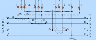
To check the transformation ratio of current transformers, assemble the circuit shown in Figure 8. For built-in current transformers, the transformation ratio is checked only on the working branches - the remaining parts of the windings are not checked.
The current in the primary circuit of the transformer is proportional to the current in the secondary circuit. The current proportionality coefficient will be the desired transformation ratio.
The isolation transformer creates on its secondary winding a voltage of about 5V and a current of about 1000A (depending on the current transformer being tested).
Removal of magnetization characteristics of current transformers.
The characteristic is measured by increasing the voltage on the secondary windings until saturation begins (but not higher than 1800V), while simultaneously measuring the current in the test winding using an ammeter.
If the windings have branches, the characteristic is taken on the working branch, while measurements are not taken on non-working branches.
The taken characteristic is compared with the typical magnetization characteristic or with the magnetization characteristics of serviceable current transformers of the same type as those being tested.
Differences from the values measured at the manufacturer or from those measured on a working current transformer of the same type as those being tested should not exceed 10%.
The magnetization characteristics are taken to check the serviceability of the current transformers. At the same time, they make sure that there are no short-circuited turns and damage to the core, and evaluate the possibilities of using the transformer in a relay protection circuit under specific conditions.
The magnetization characteristic is the dependence of the voltage supplied to the secondary winding on the current in this winding. The circuit for reading the magnetization characteristics is shown in Figure 7.
The magnetization characteristic is taken to the rated current of the transformer (secondary winding current), in cases where this is required (for especially critical transformers), the characteristic is taken before the current transformer begins to saturate (for 5-amp transformers - until the current reaches 10A).
If, when taking the characteristics, a voltage higher than 250V is required, step-up transformers with a higher voltage are used.
The current-voltage characteristic is the main one when assessing the serviceability of a CT. Such characteristics are also used to determine CT errors.
The most common CT malfunction - a turn short circuit - is detected by a sharp decrease in the current-voltage characteristic and a change in its slope. The taken characteristic is compared with the typical magnetization characteristic or with the magnetization characteristics of serviceable CTs of the same type as the one being tested, most often with the characteristics of CTs of other phases of the same connection. For such a comparison, it is sufficient that the characteristics coincide with an accuracy within the limits of their factory spread.
a) b)
a - TT TV-35, 300/5 A; b — TT TVD-500, 2000/1;
1 - serviceable current transformer; 2 - one turn is short-circuited;
3 - two turns are short-circuited; 4 - eight turns shorted
Drawing. Current-voltage characteristics for turn faults in the secondary winding
That's all I have for today.
There will be questions, I will try to answer them.
Good luck.
Transformer oil testing
When commissioning current transformers, fresh dry transformer oil before and after filling (topping up) into transformers must be tested in accordance with the requirements of Section 25. During operation, transformer oil from current transformers with voltages up to 35 kV inclusive may not be tested. Oil from current transformers 110-220 and 330-500 kV, not equipped with an operating voltage control system, is tested in accordance with the requirements of paragraphs. 1-3 tables 25.4 taking into account section. 25.3.2 – once every 2 years (for sealed current transformers – according to the manufacturer’s instructions). Oil from current transformers equipped with a control system under operating voltage, when the controlled parameters reach the limit values given in table. 4, tested according to the requirements of table. 25.4 (clauses 1-7).
Table 4
| Voltage class, kV | Limit values, %, of parameters δtgδ and δY/Y | |
| with periodic monitoring | with continuous monitoring | |
| 220 | 2,0 | 3,0 |
| 330-500 | 1,5 | 2,0 |
| 750 | 1,0 | 1,5 |
For oil-filled cascade current transformers, the condition of the transformer oil in each stage is assessed according to standards corresponding to the operating voltage of the stage.
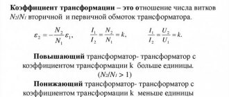
Definition
The definition of technical characteristics for a transformer is prescribed in GOST 7746 2001 under the title “Current transformers. General technical conditions". This document belongs to the interstate class, that is, it applies to all devices manufactured anywhere in the country.
In order to understand the definition, you need to get acquainted with what the average safety factor means. This indicator in turn is the ratio of the rated safety current and the primary (also the rated total value). The safety factor is inherently the main parameter that determines the required pulse increase factor.
The last characteristic is important, since in production conditions situations are often observed when it increases from the nominal value. This occurs when there is a short circuit in the circuit in most cases.
The situation is determined by the fact that the TS core goes into saturation, while no growth is observed in the secondary, which in turn ensures protection of all connected loads to the equipment.
Possible problems
CTs have an insulated housing and terminals for connecting the source and secondary devices. Some devices can be tested independently; to check the performance of others, you must have qualifications and appropriate access to high-voltage equipment. The cause of the malfunction is damage:
- Frame;
- Magnetic core;
- Broken windings;
- Winding insulation;
- Wear of contacts and outputs.
CT error limits for classes P
All characteristics are indicated in the documentation for specific types of devices. Also, information is registered separately for each device. Specifically for accuracy classes P, limits of permissible current and angular errors are established.
For transformers with power class 5P at a normal current with a maximum full multiple of 5 percent, the permissible error limits are as follows:
- current – + or – 1%;
- angular + or - 60 percent, which is identical to 1.9.
The limits indicated in the tables are met, since this is the first of the safety requirements.
For a device of accuracy class 10P, the required maximum factor is 10%, respectively. The maximum possible error limit during operation is 3 percent. At the same time, data on angular errors is not presented, since they are not standardized.